EP0760434A1 - Palier lisse avec capteur d'usure - Google Patents
Palier lisse avec capteur d'usure Download PDFInfo
- Publication number
- EP0760434A1 EP0760434A1 EP19960305668 EP96305668A EP0760434A1 EP 0760434 A1 EP0760434 A1 EP 0760434A1 EP 19960305668 EP19960305668 EP 19960305668 EP 96305668 A EP96305668 A EP 96305668A EP 0760434 A1 EP0760434 A1 EP 0760434A1
- Authority
- EP
- European Patent Office
- Prior art keywords
- bearing
- bearing ring
- lined
- electrical conductors
- liner
- Prior art date
- Legal status (The legal status is an assumption and is not a legal conclusion. Google has not performed a legal analysis and makes no representation as to the accuracy of the status listed.)
- Withdrawn
Links
- 239000004020 conductor Substances 0.000 claims abstract description 39
- 238000012544 monitoring process Methods 0.000 claims description 5
- 230000000007 visual effect Effects 0.000 claims 1
- 239000011248 coating agent Substances 0.000 description 3
- 238000000576 coating method Methods 0.000 description 3
- 230000005611 electricity Effects 0.000 description 2
- 238000002955 isolation Methods 0.000 description 2
- 239000002861 polymer material Substances 0.000 description 2
- 238000012360 testing method Methods 0.000 description 2
- 239000004809 Teflon Substances 0.000 description 1
- 229920006362 Teflon® Polymers 0.000 description 1
- 230000004323 axial length Effects 0.000 description 1
- 239000002131 composite material Substances 0.000 description 1
- 238000010276 construction Methods 0.000 description 1
- 230000003247 decreasing effect Effects 0.000 description 1
- 210000003298 dental enamel Anatomy 0.000 description 1
- 230000000694 effects Effects 0.000 description 1
- 238000009413 insulation Methods 0.000 description 1
- 230000002452 interceptive effect Effects 0.000 description 1
- 239000000463 material Substances 0.000 description 1
- 239000002184 metal Substances 0.000 description 1
- 229920000642 polymer Polymers 0.000 description 1
- 238000005096 rolling process Methods 0.000 description 1
- 230000011664 signaling Effects 0.000 description 1
- 229910001220 stainless steel Inorganic materials 0.000 description 1
- 239000010935 stainless steel Substances 0.000 description 1
Images

Classifications
-
- G—PHYSICS
- G01—MEASURING; TESTING
- G01M—TESTING STATIC OR DYNAMIC BALANCE OF MACHINES OR STRUCTURES; TESTING OF STRUCTURES OR APPARATUS, NOT OTHERWISE PROVIDED FOR
- G01M13/00—Testing of machine parts
- G01M13/04—Bearings
-
- F—MECHANICAL ENGINEERING; LIGHTING; HEATING; WEAPONS; BLASTING
- F16—ENGINEERING ELEMENTS AND UNITS; GENERAL MEASURES FOR PRODUCING AND MAINTAINING EFFECTIVE FUNCTIONING OF MACHINES OR INSTALLATIONS; THERMAL INSULATION IN GENERAL
- F16C—SHAFTS; FLEXIBLE SHAFTS; ELEMENTS OR CRANKSHAFT MECHANISMS; ROTARY BODIES OTHER THAN GEARING ELEMENTS; BEARINGS
- F16C17/00—Sliding-contact bearings for exclusively rotary movement
- F16C17/12—Sliding-contact bearings for exclusively rotary movement characterised by features not related to the direction of the load
- F16C17/24—Sliding-contact bearings for exclusively rotary movement characterised by features not related to the direction of the load with devices affected by abnormal or undesired positions, e.g. for preventing overheating, for safety
- F16C17/246—Sliding-contact bearings for exclusively rotary movement characterised by features not related to the direction of the load with devices affected by abnormal or undesired positions, e.g. for preventing overheating, for safety related to wear, e.g. sensors for measuring wear
-
- F—MECHANICAL ENGINEERING; LIGHTING; HEATING; WEAPONS; BLASTING
- F16—ENGINEERING ELEMENTS AND UNITS; GENERAL MEASURES FOR PRODUCING AND MAINTAINING EFFECTIVE FUNCTIONING OF MACHINES OR INSTALLATIONS; THERMAL INSULATION IN GENERAL
- F16C—SHAFTS; FLEXIBLE SHAFTS; ELEMENTS OR CRANKSHAFT MECHANISMS; ROTARY BODIES OTHER THAN GEARING ELEMENTS; BEARINGS
- F16C17/00—Sliding-contact bearings for exclusively rotary movement
- F16C17/02—Sliding-contact bearings for exclusively rotary movement for radial load only
-
- F—MECHANICAL ENGINEERING; LIGHTING; HEATING; WEAPONS; BLASTING
- F16—ENGINEERING ELEMENTS AND UNITS; GENERAL MEASURES FOR PRODUCING AND MAINTAINING EFFECTIVE FUNCTIONING OF MACHINES OR INSTALLATIONS; THERMAL INSULATION IN GENERAL
- F16C—SHAFTS; FLEXIBLE SHAFTS; ELEMENTS OR CRANKSHAFT MECHANISMS; ROTARY BODIES OTHER THAN GEARING ELEMENTS; BEARINGS
- F16C2233/00—Monitoring condition, e.g. temperature, load, vibration
-
- F—MECHANICAL ENGINEERING; LIGHTING; HEATING; WEAPONS; BLASTING
- F16—ENGINEERING ELEMENTS AND UNITS; GENERAL MEASURES FOR PRODUCING AND MAINTAINING EFFECTIVE FUNCTIONING OF MACHINES OR INSTALLATIONS; THERMAL INSULATION IN GENERAL
- F16C—SHAFTS; FLEXIBLE SHAFTS; ELEMENTS OR CRANKSHAFT MECHANISMS; ROTARY BODIES OTHER THAN GEARING ELEMENTS; BEARINGS
- F16C2326/00—Articles relating to transporting
- F16C2326/43—Aeroplanes; Helicopters
Definitions
- This invention relates generally to lined bearings and, more particularly, to a lined bearing with a sensor permitting remote monitoring of wear.
- Lined bearings are used in a wide variety of applications and, due to improvements in bearing design and bearing materials, lined bearings are now used in many applications where rolling element bearings were used previously.
- lined bearings with a liner of polymer material may be used in place of needle roller bearings to realise substantial savings in weight and complexity.
- large numbers of such bearings are required to support the movable control surfaces on large aircraft, considerable effort and expense are required periodically to check each of the lined bearings for excessive wear.
- a lined bearing comprising an inner bearing ring having an axis, an outer bearing ring concentric with the inner bearing ring and providing an annular space therebetween, one of the inner bearing ring and the outer bearing ring being stationary and the other of the inner bearing ring and the outer bearing ring being rotatable about the axis, and a bearing liner within the annular space and fixed to the stationary bearing ring, characterised in that a pair of electrical conductors are embedded in the bearing liner, coiled in at least one loop encircling the inner bearing ring, each of the electrical conductors being electrically isolated and located such that wear of the bearing liner will cause the rotatable bearing ring to contact and electrically connect the electrical conductors.
- a system for monitoring wear of lined bearings comprising a plurality of lined bearings, each of the lined bearings having an axis, an inner bearing ring, an outer bearing ring concentric with the inner bearing ring, one of the inner bearing ring and the outer bearing ring being stationary and the other of the inner bearing ring and the outer bearing ring being rotatable about the axis, and a bearing liner between the inner bearing ring and the outer bearing ring and fixed to the stationary bearing ring; characterised by a pair of electrical conductors embedded in the bearing liner in each of said bearings, each pair of electrical conductors being coiled in at least one loop encircling the inner bearing ring and each of the electrical conductors being electrically isolated and located such that excessive wear of the bearing liner will cause said rotatable bearing ring to contact and electrically connect the electrical conductors, and signal processing means for processing electrical signals from the electrical conductors of the lined bearings to indicate wear of
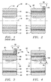
- Figure 1 illustrates a lined bearing 10, typical of the prior art, as used, for example, as an aircraft track roller bearing.
- An outer bearing ring 12 and inner bearing ring 14 are concentric about an axis 16 and are typically made of stainless steel.
- a bearing liner 18, located within an annular space between the bearing rings, may be made of a polymer material.
- Figure 2 illustrates a lined bearing 20 of the present invention, including a wear sensor.
- An outer bearing ring 22 and inner bearing ring 24 are concentric about an axis 26.
- One of the bearing rings 22 and 24 is stationary with respect to its mounting and the other bearing ring is rotatable about the axis 26.
- a bearing liner 28 is located within an annular space between the outer bearing ring 22 and inner bearing ring 24 and is fixed to the stationary bearing ring.
- a pair of electrical conductors 30 is embedded in the bearing liner 28 such that each conductor, designated A or B, is coiled in a helix or similar form with at least one loop encircling the inner bearing ring 24.
- a and B alternate along the axial length of the bearing and are electrically isolated from each other.
- the electrical conductors 30 are located within the bearing liner 28, along the stationary bearing ring, such that wear of the bearing liner will cause the rotatable bearing ring to contact and electrically connect electrical conductors A and B.
- the bearing liner 28 is made of a low-friction polymer, such as a TFE (teflon) composite, and is a poor conductor of electricity, avoiding the need to provide separate insulation of the electrical conductors 30.
- a low-friction polymer such as a TFE (teflon) composite
- they can be coated with enamel or other coating similar to that used with magnet wire.
- the outer bearing ring 22 is stationary and the inner bearing ring 24 is rotatable about the axis 26 relative to the outer bearing ring 22. At least one opening 32 within the stationary bearing ring is provided to permit electrical connection to detecting means and a remote monitor by external wires.
- Figure 3 illustrates the lined bearing 20 after excessive wear, and is enumerated as lined bearing 34 to distinguish the initial configuration.
- the outer bearing ring 22 is unchanged and the inner bearing ring 36 shows little wear but is no longer concentric about the axis 26.
- a bearing liner upper portion 38 shows little wear but a bearing liner lower portion 40 shows excessive wear.
- the excessive wear causes shorting of the electrical conductors 30 due to contact with the rotating inner bearing ring 36 that is made of metal or is coated to conduct electricity. If the electrical conductors 30 are coated to ensure electrical isolation, as described above, the coating will easily wear away when the rotating bearing ring rubs against the coating.
- Figure 4 illustrates a lined bearing 42 similar to the lined bearings 20 and 34 but having a stationary inner bearing ring 46, as found in a typical track roller bearing.
- An outer bearing ring 44 is similar to the outer bearing ring 22 of Figure 2.
- the inner bearing ring 46 is not concentric about the axis 48 due to excessive wear of the rotating outer bearing ring against a bearing liner 50 at a portion 52.
- Electrical conductors 54 are coiled around the inner bearing ring 46 in alternating A and B locations to indicate excessive wear, similar to the electrical conductors 30 of the first embodiment.
- the bearing liner is fixed to the stationary inner bearing ring 46 and is electrically connected to detector means and a remote monitor through at least one opening 56.
- Figure 5 illustrates schematically a simple means for detecting the electrical connection of the electrical conductors 30 or 54 that results with excessive wear.
- An ohmmeter 60 senses the decreased electrical resistance between A and B and can serve as a remote monitor of the lined bearing.
- a power source 62 may apply a voltage to either A or B, as illustrated schematically in Figure 6, and a voltmeter 64 may be used as a remote monitor of the lined bearing.
- Resistors 66 and 68 serve as biasing resistors and a transistor 70 serves as a switch.
- Figure 7 illustrates schematically a fuselage 72 of an airplane equipped with several lined bearings 74 along a rear control surface 76 of a wing 78. Electrical wires 80, in pairs, are joined as cable 82 connecting lined bearings 74 to a signal processing means 84.
- the signal processing means 84 may be a simple switch enabling manual connection of a detector similar to those of Figures 5 an 6 to one of the lined bearings 74 or may be more automated, such as a computerized multiplexer and signal conditioner for sequential testing of the lined bearings 74.
- Output for the signal processing means 84 may be connected by electrical wires 86 to a warning lamp or other cockpit display 88.
- the signal processing means may also, be made detachable for use by ground crews, if the built-in test feature is not desired.
- the present construction provides an effective and convenient means of monitoring lined bearings to sense excessive wear.
- Electrical conductors that serve as sensing elements are placed selectively with the bearing liner to permit only the desired amount of wear, and electrical connections are led through the stationary bearing ring without interfering with operation of the lined bearings.
- the wear sensor is particularly suited for use with airplane control surfaces using large numbers of lined bearings.
Landscapes
- Engineering & Computer Science (AREA)
- General Engineering & Computer Science (AREA)
- Mechanical Engineering (AREA)
- Physics & Mathematics (AREA)
- General Physics & Mathematics (AREA)
- Sliding-Contact Bearings (AREA)
Applications Claiming Priority (2)
| Application Number | Priority Date | Filing Date | Title |
|---|---|---|---|
| US50930695A | 1995-07-31 | 1995-07-31 | |
| US509306 | 1995-07-31 |
Publications (1)
| Publication Number | Publication Date |
|---|---|
| EP0760434A1 true EP0760434A1 (fr) | 1997-03-05 |
Family
ID=24026104
Family Applications (1)
| Application Number | Title | Priority Date | Filing Date |
|---|---|---|---|
| EP19960305668 Withdrawn EP0760434A1 (fr) | 1995-07-31 | 1996-07-31 | Palier lisse avec capteur d'usure |
Country Status (3)
| Country | Link |
|---|---|
| US (1) | US5701119A (fr) |
| EP (1) | EP0760434A1 (fr) |
| CA (1) | CA2182445A1 (fr) |
Cited By (5)
| Publication number | Priority date | Publication date | Assignee | Title |
|---|---|---|---|---|
| DE19915348A1 (de) * | 1999-04-06 | 2000-10-12 | Schaeffler Waelzlager Ohg | Gleitlager |
| FR2833321A1 (fr) * | 2001-12-11 | 2003-06-13 | Irisbus France | Liaison a rotule pour organe de vehicule routier, et organe de vehicule routier equipe d'une telle liaison |
| DE10324924A1 (de) * | 2003-06-03 | 2004-12-23 | Ab Skf | Gleitlager mit sphärisch oder zylinderisch ausgebildeten Lagerflächen |
| RU2398142C1 (ru) * | 2009-05-18 | 2010-08-27 | Государственное образовательное учреждение высшего профессионального образования "Орловский государственный технический университет" (ОрелГТУ) | Мехатронный подшипник скольжения |
| EP2689154A4 (fr) * | 2011-03-22 | 2015-05-13 | Saint Gobain Performance Plast | Bague à état de conduction électrique pouvant être transfiguré |
Families Citing this family (26)
| Publication number | Priority date | Publication date | Assignee | Title |
|---|---|---|---|---|
| US6206573B1 (en) * | 1998-05-21 | 2001-03-27 | Lsi Logic Corporation | High reliability bearing structure |
| US5998894A (en) * | 1998-08-04 | 1999-12-07 | Pacific Scientific | Modular bearing failure sensor for an electrical generator |
| US6595045B1 (en) | 2000-10-16 | 2003-07-22 | Veridian Engineering, Inc. | Vehicular sensors |
| US6498470B2 (en) | 2001-03-02 | 2002-12-24 | Honeywell International, Inc. | Insulative contact sensor |
| US7034711B2 (en) * | 2001-08-07 | 2006-04-25 | Nsk Ltd. | Wireless sensor, rolling bearing with sensor, management apparatus and monitoring system |
| DE10140683A1 (de) * | 2001-08-24 | 2003-03-06 | Zf Lemfoerder Metallwaren Ag | Kugelgelenk |
| DE10159071A1 (de) * | 2001-12-01 | 2003-06-12 | Ina Schaeffler Kg | Verschleißanzeige für eine Spannvorrichtung |
| US7270890B2 (en) * | 2002-09-23 | 2007-09-18 | Siemens Power Generation, Inc. | Wear monitoring system with embedded conductors |
| US7452155B2 (en) * | 2003-02-27 | 2008-11-18 | ZF Lemförder Metallwaren AG | Ball and socket joint |
| US8264347B2 (en) * | 2008-06-24 | 2012-09-11 | Trelleborg Sealing Solutions Us, Inc. | Seal system in situ lifetime measurement |
| DE102012106295A1 (de) * | 2012-07-12 | 2014-10-30 | Institut Für Verbundwerkstoffe Gmbh | Gleitlager sowie Verfahren zur Bestimmung des Verschleißes eines Gleitlagers |
| DE102014204824A1 (de) * | 2014-03-14 | 2015-09-17 | Invent Umwelt-Und Verfahrenstechnik Ag | Rührvorrichtung für Abwasser |
| DE102014110383A1 (de) | 2014-04-01 | 2015-10-01 | Becker Marine Systems Gmbh & Co. Kg | Lager zum Lagern einer Welle, insbesondere eines Ruderschaftes, elektronische Lagerspielmessvorrichtung, Ruder umfassend ein Lager zum Lagern einer Welle und Verfahren zur Messung eines Verschleißes eines Lagers zum Lagern einer Welle |
| GB2534191A (en) * | 2015-01-16 | 2016-07-20 | Mahle Int Gmbh | Sliding bearing |
| JP6491060B2 (ja) * | 2015-08-21 | 2019-03-27 | ミネベアミツミ株式会社 | 摺動部品、これを備える摩耗検知システム及びヨーシステム、並びに該ヨーシステムを備える風力発電装置 |
| DE202016102133U1 (de) * | 2016-04-21 | 2017-05-23 | Igus Gmbh | Gleitlager, Kunststoffgleitelement, System und Verwendung zur Verschleißerkennung |
| US11690645B2 (en) | 2017-05-03 | 2023-07-04 | Medtronic Vascular, Inc. | Tissue-removing catheter |
| CN110573098B (zh) | 2017-05-03 | 2022-08-23 | 美敦力瓦斯科尔勒公司 | 组织移除导管 |
| GB2565555B (en) * | 2017-08-15 | 2020-07-08 | Mahle Int Gmbh | Sliding component and method |
| PL3864309T3 (pl) * | 2018-10-08 | 2023-08-28 | Igus Gmbh | Element ślizgowy z tworzywa sztucznego z funkcję czujnika, zwłaszcza z wykrywaniem zużycia |
| US11819236B2 (en) | 2019-05-17 | 2023-11-21 | Medtronic Vascular, Inc. | Tissue-removing catheter |
| DE102019008762A1 (de) * | 2019-12-14 | 2021-06-17 | Hochschule Mittweida (Fh) | Einrichtung zur Überwachung eines Gleitlagers mit einem ersten Teil und einem zweiten Teil, die relativ zueinander bewegbar sind |
| EP3992487B1 (fr) * | 2020-10-30 | 2024-07-17 | Meritor Heavy Vehicle Braking Systems (UK) Limited | Ensemble de guidage pour frein à disque |
| EP4047233A1 (fr) | 2021-02-17 | 2022-08-24 | Flender GmbH | Accouplement élastique en torsion pourvu de capteur d'usure |
| IT202300008859A1 (it) * | 2023-05-04 | 2024-11-04 | Cnh Ind Italia Spa | Cerniera migliorata per un veicolo da lavoro |
| CN116879096A (zh) * | 2023-08-24 | 2023-10-13 | 西南交通大学 | 一种动态激振下的滚动汇流环磨损疲劳试验装置 |
Citations (5)
| Publication number | Priority date | Publication date | Assignee | Title |
|---|---|---|---|---|
| DE2115506A1 (de) * | 1971-03-31 | 1972-10-05 | Kloeckner Werke Ag | Einrichtung zur Überwachung des Verschleißes von Lagern |
| JPS5618119A (en) * | 1979-07-20 | 1981-02-20 | Hitachi Ltd | Life detection of oilless type solid lubricating material |
| US4320431A (en) * | 1980-02-26 | 1982-03-16 | Westinghouse Electric Corp. | Fluid circulating pump |
| JPS6154402A (ja) * | 1984-08-27 | 1986-03-18 | Inoue Japax Res Inc | 合成樹脂機械部品の摩耗を検出する方法 |
| GB2192949A (en) * | 1986-07-25 | 1988-01-27 | Wickers Shipbuilding & Enginee | Indicating wear in bearings |
Family Cites Families (6)
| Publication number | Priority date | Publication date | Assignee | Title |
|---|---|---|---|---|
| US3108264A (en) * | 1957-07-08 | 1963-10-22 | Heinoo Lauri | Bearing wear sensor |
| US3102759A (en) * | 1960-05-19 | 1963-09-03 | John T Stewart | Journal bearing wear detector |
| NO134348C (fr) * | 1971-02-22 | 1976-09-22 | Asea Ab | |
| US3897116A (en) * | 1971-10-07 | 1975-07-29 | Crane Co | Bearing wear detector |
| SU727886A1 (ru) * | 1978-07-26 | 1980-04-15 | Воинская Часть 27177-Е | Устройство дл определени износа подшипников скольжени |
| US4584865A (en) * | 1984-07-30 | 1986-04-29 | Lawrence Pump And Engine Company | Device and method for testing for motor bearing wear |
-
1996
- 1996-07-31 CA CA 2182445 patent/CA2182445A1/fr not_active Abandoned
- 1996-07-31 EP EP19960305668 patent/EP0760434A1/fr not_active Withdrawn
-
1997
- 1997-01-13 US US08/782,375 patent/US5701119A/en not_active Expired - Lifetime
Patent Citations (5)
| Publication number | Priority date | Publication date | Assignee | Title |
|---|---|---|---|---|
| DE2115506A1 (de) * | 1971-03-31 | 1972-10-05 | Kloeckner Werke Ag | Einrichtung zur Überwachung des Verschleißes von Lagern |
| JPS5618119A (en) * | 1979-07-20 | 1981-02-20 | Hitachi Ltd | Life detection of oilless type solid lubricating material |
| US4320431A (en) * | 1980-02-26 | 1982-03-16 | Westinghouse Electric Corp. | Fluid circulating pump |
| JPS6154402A (ja) * | 1984-08-27 | 1986-03-18 | Inoue Japax Res Inc | 合成樹脂機械部品の摩耗を検出する方法 |
| GB2192949A (en) * | 1986-07-25 | 1988-01-27 | Wickers Shipbuilding & Enginee | Indicating wear in bearings |
Cited By (7)
| Publication number | Priority date | Publication date | Assignee | Title |
|---|---|---|---|---|
| DE19915348A1 (de) * | 1999-04-06 | 2000-10-12 | Schaeffler Waelzlager Ohg | Gleitlager |
| DE19915348B4 (de) * | 1999-04-06 | 2019-06-27 | Schaeffler Technologies AG & Co. KG | Gleitlager |
| FR2833321A1 (fr) * | 2001-12-11 | 2003-06-13 | Irisbus France | Liaison a rotule pour organe de vehicule routier, et organe de vehicule routier equipe d'une telle liaison |
| DE10324924A1 (de) * | 2003-06-03 | 2004-12-23 | Ab Skf | Gleitlager mit sphärisch oder zylinderisch ausgebildeten Lagerflächen |
| DE10324924B4 (de) | 2003-06-03 | 2021-08-26 | Ab Skf | Verfahren zum Ermitteln einer von einem Gleitlager mit sphärisch oder zylindrisch ausgebildeten Lagerflächen aufgenommenen Last |
| RU2398142C1 (ru) * | 2009-05-18 | 2010-08-27 | Государственное образовательное учреждение высшего профессионального образования "Орловский государственный технический университет" (ОрелГТУ) | Мехатронный подшипник скольжения |
| EP2689154A4 (fr) * | 2011-03-22 | 2015-05-13 | Saint Gobain Performance Plast | Bague à état de conduction électrique pouvant être transfiguré |
Also Published As
| Publication number | Publication date |
|---|---|
| US5701119A (en) | 1997-12-23 |
| CA2182445A1 (fr) | 1997-02-01 |
Similar Documents
| Publication | Publication Date | Title |
|---|---|---|
| US5701119A (en) | Lined bearing with wear sensor | |
| US4387336A (en) | Method and apparatus for cable conductor shield fault detection | |
| US8319628B2 (en) | Three-phase faulted circuit indicator | |
| US6653943B2 (en) | Suspension rope wear detector | |
| CN104426039B (zh) | 集电环单元以及用于检测集电环单元的状态的方法 | |
| US4493155A (en) | Apparatus for remotely indicating angular position | |
| US20180017611A1 (en) | Method and apparatus for an electrical fault detecting system for a circuit | |
| EP3168361B1 (fr) | Câble de palan de sauvetage d'aéronef conçu pour inspection continue | |
| CA2329405C (fr) | Cables de fibres synthetiques a connexion par contact et a securite controlee | |
| CN101456509B (zh) | 电梯钢丝绳检查装置 | |
| US6034531A (en) | Monitoring of the wear of sliding electrical contacts and its application to the state-dependent and/or predictive maintenance of a device having sliding electrical contacts | |
| US4584865A (en) | Device and method for testing for motor bearing wear | |
| GB2042182A (en) | Magnetic contamination detector | |
| JP2013525701A (ja) | 軸受装置、軸受装置の軸受面の磨耗を検出する方法および軸受装置の使用 | |
| US5020741A (en) | Aircraft propeller with improved electrically de-icer leads | |
| EP0356017A2 (fr) | Appareil de détection de fuites de liquides | |
| US3710241A (en) | Apparatus for detecting faults in extruded insulating or dielectric material | |
| US3405356A (en) | System including two pairs of voltage electrodes for detecting discontinuities in insulation coatings on conductive conduit | |
| JP4257839B2 (ja) | 電力ケーブル遮蔽導体の接地不良検出装置 | |
| US3763426A (en) | Method and apparatus for testing twisted pair wire to locate electrical insulation faults or measure twist or wire runout or sense breaks in the conductors | |
| US6498470B2 (en) | Insulative contact sensor | |
| JP2007305478A (ja) | 電気ケーブルの断線検知装置および断線検知方法 | |
| US20060146911A1 (en) | Overheat detection sensor | |
| SE461685B (sv) | Foerfarande och anordning foer glimprovning av i transformatorolja nedsaenkt underisolant hos genomfoeringar | |
| SU1404803A1 (ru) | Емкостный датчик дл контрол толщины изол ции проводов |
Legal Events
| Date | Code | Title | Description |
|---|---|---|---|
| PUAI | Public reference made under article 153(3) epc to a published international application that has entered the european phase |
Free format text: ORIGINAL CODE: 0009012 |
|
| AK | Designated contracting states |
Kind code of ref document: A1 Designated state(s): DE FR GB SE |
|
| 17P | Request for examination filed |
Effective date: 19970822 |
|
| 17Q | First examination report despatched |
Effective date: 19980827 |
|
| STAA | Information on the status of an ep patent application or granted ep patent |
Free format text: STATUS: THE APPLICATION IS DEEMED TO BE WITHDRAWN |
|
| 18D | Application deemed to be withdrawn |
Effective date: 19990108 |