EP0760686B1 - Behälter für waschmaschinen oder autoklaven - Google Patents
Behälter für waschmaschinen oder autoklaven Download PDFInfo
- Publication number
- EP0760686B1 EP0760686B1 EP95918458A EP95918458A EP0760686B1 EP 0760686 B1 EP0760686 B1 EP 0760686B1 EP 95918458 A EP95918458 A EP 95918458A EP 95918458 A EP95918458 A EP 95918458A EP 0760686 B1 EP0760686 B1 EP 0760686B1
- Authority
- EP
- European Patent Office
- Prior art keywords
- base
- tray
- container
- perforations
- container component
- Prior art date
- Legal status (The legal status is an assumption and is not a legal conclusion. Google has not performed a legal analysis and makes no representation as to the accuracy of the status listed.)
- Expired - Lifetime
Links
Images


Classifications
-
- A—HUMAN NECESSITIES
- A61—MEDICAL OR VETERINARY SCIENCE; HYGIENE
- A61L—METHODS OR APPARATUS FOR STERILISING MATERIALS OR OBJECTS IN GENERAL; DISINFECTION, STERILISATION OR DEODORISATION OF AIR; CHEMICAL ASPECTS OF BANDAGES, DRESSINGS, ABSORBENT PADS OR SURGICAL ARTICLES; MATERIALS FOR BANDAGES, DRESSINGS, ABSORBENT PADS OR SURGICAL ARTICLES
- A61L2/00—Disinfection or sterilisation of materials or objects, in general; Accessories therefor
- A61L2/26—Accessories
-
- A—HUMAN NECESSITIES
- A61—MEDICAL OR VETERINARY SCIENCE; HYGIENE
- A61L—METHODS OR APPARATUS FOR STERILISING MATERIALS OR OBJECTS IN GENERAL; DISINFECTION, STERILISATION OR DEODORISATION OF AIR; CHEMICAL ASPECTS OF BANDAGES, DRESSINGS, ABSORBENT PADS OR SURGICAL ARTICLES; MATERIALS FOR BANDAGES, DRESSINGS, ABSORBENT PADS OR SURGICAL ARTICLES
- A61L2/00—Disinfection or sterilisation of materials or objects, in general; Accessories therefor
- A61L2/02—Disinfection or sterilisation of materials or objects, in general; Accessories therefor using physical processes
- A61L2/04—Heat
- A61L2/06—Hot gas
-
- A—HUMAN NECESSITIES
- A61—MEDICAL OR VETERINARY SCIENCE; HYGIENE
- A61L—METHODS OR APPARATUS FOR STERILISING MATERIALS OR OBJECTS IN GENERAL; DISINFECTION, STERILISATION OR DEODORISATION OF AIR; CHEMICAL ASPECTS OF BANDAGES, DRESSINGS, ABSORBENT PADS OR SURGICAL ARTICLES; MATERIALS FOR BANDAGES, DRESSINGS, ABSORBENT PADS OR SURGICAL ARTICLES
- A61L2/00—Disinfection or sterilisation of materials or objects, in general; Accessories therefor
- A61L2/16—Disinfection or sterilisation of materials or objects, in general; Accessories therefor using chemical substances
- A61L2/18—Liquid substances
Definitions
- This invention relates to a container component for enabling fluid flow therethrough for cleaning or sterilising of the contents within the container.
- Trays made of stainless steel and synthetic materials are known for holding dental and medical instruments for sterilisation in an autoclave.
- Such stainless steel trays have a base made of a sheet of flat stainless steel material which has an array of cylindrical holes drilled through the base to allow steam in the autoclave to pass through the base.
- said trays are expensive and/or may not allow steam or washing liquid to reach all parts of the instruments resting on them.
- Patent Specification No. AU-24539/88 discloses an autoclave container in the form of a tray made of a plastics material, the tray having a base with perforations defined by walls, the walls progressively widening from a top point to a flat bottom surface of the base.
- the flat bottom surface enables a substantial amount of the heat stored within the plastics material after the tray has been an autoclave to be yielded up through the flat base surface and thereby help evaporate any moisture, such as condensation, particularly within the filter material placed around the tray when in the autoclave.
- the tray in this patent specification would not be particularly effective in a washer where water jets are directed upwardly against the base of the tray, since the large flat bottom surface area would deflect much of the water downwardly rather than allowing the water to pass upwardly through the perforations to reach the instruments in the tray.
- a type of closed autoclave vessel frequently used in hospitals for holding instruments to be sterilised in an autoclave has a square bottom of about 40cm width and which has a perforated central opening, e.g. having a diameter of about 10cm.
- the circular central opening in use is covered by a permeable filter material.
- the lid of the vessel is similarly constructed, having a 10cm diameter circular perforated opening in the centre of the lid covered in use by a permeable filter.
- Inside the closed vessel there can be a tray which is perforated and which supports the instruments to be sterilised. Steam flows through the upper circular opening in the lid to reach the interior of the vessel and passes out through the lower central perforated opening.
- a container component for enabling cleaning of articles located within the container component by fluid flow through the component, comprising a base, the base having perforations provided over substantially the entire area where the articles are in use located and through which the cleaning fluid can flow, the perforations in the base being defined by perforation walls, characterised in that each of the walls in vertical cross section having a narrow top, widening in a downwards direction to a maximum width and then narrowing again to a narrow bottom, the maximum width being less than the distance from the top to the bottom.
- a container for enabling cleaning of articles located within the container by fluid flow through the container comprising:
- each perforation wall comprises a top point
- the narrow bottom of each perforation wall comprises a bottom point.
- the external bottom surface of a tray will present the bottom points of the perforation walls as contact points so that if, for example, a tray is stacked immediately on top of another container having a lid constructed according to the invention, the contact points will be the bottom points of the walls of the tray and the top points of the walls of the lid, thus minimising contact area where moisture may collect.
- the base may be substantially planar and each wall in vertical cross section may be substantially elliptical with the major axis of the elliptical cross section being orthogonal to the plane of the base.
- each wall in vertical cross section may widen gently and progressively in a downwards direction from the narrow top to the maximum width and then may narrow rapidly and sharply to the narrow bottom, or vice versa.
- each wall is less than the distance from the top point to the bottom point, the proportion of the total area of the base in plan view occupied by the area of the perforations, and hence the area open to flow of cleaning fluid through the base can be maximised while at the same time the walls can provide sufficient structural strength.
- the maximum width of each wall may be, for example, less than half the distance from the top to the bottom thereof.
- the walls may define a regular geometric mesh pattern. For example, with walls arranged in a square mesh pattern, the walls having a maximum width of 2mm and the spacing between opposite walls of each square perforation being 3.5mm, about 40% of the area of the base will in plan view be defined by the sum of the areas of the perforations.
- the cumulative area of the perforations when the base is viewed in plan view may be greater than 30%, e.g. equal to or greater than 40%, of the total area of the base.
- the container component according to the first aspect of the invention may comprise a tray, the base of the component defining a bottom of the tray, a plurality of side portions located round the perimeter of the base, the perforations in the base being provided over substantially the entire surface area out to the perimeter where the side portions are located, so that the articles to be cleaned are located by the side portions entirely within the perimeter of the base where the perforations are provided, the tray having an open top through which the cleaning fluid can flow.
- the container in use may have an outside wrap such as a filter membrane round the outside, or may have a filter membrane held within the container so that cleaning fluid passes through the filter membrane in flowing to or flowing from the articles.
- an outside wrap such as a filter membrane round the outside, or may have a filter membrane held within the container so that cleaning fluid passes through the filter membrane in flowing to or flowing from the articles.
- the container component may be, as mentioned above, in the form of an open-topped tray for containing articles to be cleaned.
- a container or cassette comprising a bottom section of a two part enclosure, such as an autoclave vessel having a bottom section in which the articles are located and a cover or lid section which fits to and is secured to the bottom section.
- an autoclave vessel having a bottom section in which the articles are located
- a cover or lid section which fits to and is secured to the bottom section.
- Either or both the bottom section and the lid section of the two part vessel may be constructed according to the present invention.
- the construction of the walls according to the invention facilitates washing liquid which is directed against the base being deflected or directed so as to pass through the perforations into the space where the articles to be cleaned are located.
- the container component may be made of a plastics material, particularly in the case of use in sterilising operations being a material capable of withstanding autoclave temperatures.
- a preferred material is polypropylene.
- the two part container shown in Figs. 1 and 2 comprises a tray 10 and a cover or lid 20 each of which embodies the present invention.
- the invention also relates to simple open topped trays such as the tray 10, e.g. for holding dental instruments to be placed in a washing apparatus where washing water containing disinfectant is directed in multiple directions within the washer so as to pass through the tray and wash the articles in the tray.
- the tray 10 includes a base 11. Similarly the lid 20 has a base 21.
- the base 11 has perforations 12 and similarly the lid 20 has perforations 22 to allow cleaning fluid, such as water in a washer or steam in an autoclave, to pass through the base 11 or 21 to contact articles received within the tray 10.
- the tray 10 and lid 20 can be moulded from plastics material such as polypropylene capable of withstanding autoclave temperatures.
- the tray 10 has a side wall 17 extending upwardly from the perimeter or edge of the perforated base 11, and the lid 20 has side wall 27 having a complementary shape at its edge to the top of the side wail 17 to enable the lid 20 to fit to the tray 10.
- the perforations 12 are defined by perforation walls 13.
- Each wall 13 in vertical cross-section is elliptical with the major axis vertical so as to commence at a top point 14, widen in a downwards direction to a maximum width 15 corresponding to the minor axis of the ellipse, and then narrow to a bottom point 16.
- the maximum width 15 is less than the distance from the top point 14 to the bottom point 16, i.e. the major axis. In Figs. 1 and 2, the width 15 is less than half the distance from point 14 to point 16.
- the cumulative area of the perforations 12 in plan view can be maximised for flow of water or steam through the perforations.
- the narrowing of the shape from the width 15 downwardly to the bottom point 16 enables much of the water directed upwardly in a washer against the tray 10 to be deflected into the perforations 12 so that most of the water being directed upwardly can continue to flow upwardly through the perforations 12 to reach articles within the tray 10 even if the water first impinges on the walls 13.
- the bottom points 16 of the tray 10 define a bottom plane 18 and the bottom edge 19 of the wall 17 meets but does not extend below this plane 18.
- the walls 13 and perforations 12 are provided across the entire area of the base 11 so that the bottom edge 19 of the side wall 17 presents only the same area in bottom plan view as a perforation wall 13. This enables articles in the tray 10, even if they are located at one side against a side wall 17, to be reached and contacted by cleaning fluid passing upwardly or downwardly through the container.
- the lid 20 so that the top points 24 of the walls 23 define a plane 28 and the side wall 27 at its top edge 29 does not project above this plane 28.
- This construction enables containers comprising tray 10 and lid 20 as shown in Fig. 1 to be stacked one on top of each other with contact points being restricted to the bottom points 16 of tray 10 meeting and resting on top points 24 of a lid 20. This minimises the contact surface areas between stacked containers to minimise obstruction to flow of cleaning fluid through the stacked containers and also to minimise areas where moisture could collect at the areas of contact.
- Fig. 3a shows the point contact provided by the bottom point 16 of wall 13 meeting the top point 24 of wall 23.
- Figs. 3b to 3e show alternative cross-sectional shapes for walls 13, 23 which still satisfy the parameters of the present invention and enable point contact of abutting container component bases.
- Fig. 4 shows a fragmentary cross-section of the lid of an enclosed autoclave basket or vessel, the lid 30 having a base 31 provided with perforations 32 through which steam can flow into the vessel.
- the walls 33 have the shape shown in Fig. 3b and satisfy the parameters of the present invention.
- the walls 33 in cross-section start at a narrow top point 34, widen downwardly to a maximum width 35 and then narrow to a bottom point 36.
- the cross-section rapidly narrows from the maximum width 35 to the bottom point 36 while the widening from the top point 34 to the maximum width 35 is shown as a half ellipse.
- the perforations 32 and walls 33 extend completely to the edge of the base 31 where the side wall 37 joins with the base 31 without the top edge 39 of the wall 37 projecting beyond the plane 38 defined by the top points 34.
- a perforated filter retainer 40 which is used to clamp a filtering membrane 41 such as a polypropylene fibre gauze between the filter retainer 40 and the base 31.
- the filter retainer 40 can be clamped or retained within the lid 30 by any convenient attaching or clamping means (not shown)
- the filter retainer is constructed as a mirror image of the base 31 so that the filtering membrane 41 is clamped between the bottom points 36 of the base 31 and complementary co-operating top points 44 provided by the walls 43 of the retainer 40.
- a tray forming the bottom of the autoclave container (of which Fig. 4 shows the lid assembly 30, 40, 41) can be substantially a mirror image of the lid construction shown in Fig. 4 so that the entire autoclave container can have a large area of perforations in the tray and also in the lid through which steam can flow.
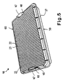
- the tray 50 and lid 60 can form a closeable cassette 46.
- the cassette 46 is formed from a tray 50 and a lid 60 which are not mirror images, the general structure is similar to the structure of the tray 10 and lid 20 shown in Fig. 1.
- the tray 50 and the lid 60 are rectangular and each includes a base 11, 21 having perforations 12, 22 to allow cleaning fluid, such as water or steam, to enter into the cassette 46, contact the articles therein and exit the cassette.
- the perforations in the tray 50 of cassette 46 of Fig. 5 can be defined by perforation walls as shown in Fig. 2.
- the lid 60 has perforations 22 defined by perforation walls 23.
- Each wall 13, 23 in vertical cross-section is elliptical with the major axis vertical so as to commence at a top point, widen in a downwards direction to a maximum width corresponding to the minor axis of the ellipse, and then narrow to a bottom point. The maximum width is less than the distance from the top point to the bottom point.
- each tongue 47 is inserted through the corresponding slot 48 of the lid 60 when the lid 60 is placed on the tray 50 in a closed position.
- the tongues 47 extend up from close to the base of the tray so as to provide a useable degree of resilience. This resilience is used to close the cassette 46 by the resilient tongue 47 being able to be moved inwardly from its resting position while being inserted through the corresponding slot 48 and, upon release, engage the respective outer side of the slot 48 while trying to return to its resting position.
- Each tongue 47 includes a step 49 extending across its outer side to engage the end of the lid 60 so as to releasably lock the lid 60 onto the tray 50.
- the container component whether it be a tray or lid or cassette, according to the present invention enables articles to be effectively reached by cleaning fluid, such as washing liquid in a washer or steam in an autoclave.
Landscapes
- Health & Medical Sciences (AREA)
- Animal Behavior & Ethology (AREA)
- Public Health (AREA)
- Veterinary Medicine (AREA)
- Epidemiology (AREA)
- Life Sciences & Earth Sciences (AREA)
- General Health & Medical Sciences (AREA)
- Chemical & Material Sciences (AREA)
- General Chemical & Material Sciences (AREA)
- Chemical Kinetics & Catalysis (AREA)
- Apparatus For Disinfection Or Sterilisation (AREA)
- Dental Tools And Instruments Or Auxiliary Dental Instruments (AREA)
- Cleaning By Liquid Or Steam (AREA)
- Table Devices Or Equipment (AREA)
- Cleaning In General (AREA)
Claims (10)
- Behälterkomponente, die die Reinigung von in der Behälterkomponente befindlichen Gegenständen durch eine Fluidströmung durch die Komponente ermöglicht, umfassend eine Grundplatte (11; 21, 31), die Perforationen (12; 22; 32) besitzt, die im wesentlichen in der gesamten Fläche vorgesehen sind, auf der sich die Gegenstände im Gebrauch befinden, und durch die das Reinigungsfluid strömen kann, wobei die Perforationen in der Grundplatte durch Perforationswände (13; 23; 33) definiert sind, dadurch gekennzeichnet, daß jede der Wände im vertikalen Querschnitt ein schmales oberes Ende (14; 24; 34) besitzt, sich in Abwärtsrichtung auf eine maximale Breite (15; 35) erweitert und sich dann erneut zu einem schmalen unteren Ende (16; 36) verschmälert, wobei die maximale Breite (15; 35) kleiner als der Abstand vom oberen Ende (14; 24; 34) zum unteren Ende (16; 36) ist.
- Behälterkomponente nach Anspruch 1, wobei das schmale obere Ende (14; 24; 34) jeder Perforationswand (13; 23; 33) einen oberen Punkt besitzt und das schmale untere Ende (16; 36) jeder Perforationswand einen unteren Punkt besitzt.
- Behälterkomponente nach Anspruch 1 oder 2, wobei die Grundplatte (11; 21; 31) im wesentlichen eben ist und wobei jede Wand (13; 23; 33) im vertikalen Querschnitt im wesentlichen elliptisch ist, wobei die Hauptachse des elliptischen Querschnitts zur Ebene der Grundplatte senkrecht ist.
- Behälterkomponente nach Anspruch 1 oder 2, wobei sich jede Wand (13; 23; 33) im vertikalen Querschnitt in Abwärtsrichtung geringfügig und allmählich vom schmalen oberen Ende (14; 24; 34) zur maximalen Breite (15; 35) erweitert und sich dann schnell und plötzlich zum schmalen unteren Ende (16; 36) verschmälert, oder umgekehrt.
- Behälterkomponente nach einem der vorhergehenden Ansprüche, wobei die maximale Breite (15; 35) jeder Wand (13; 23; 33) kleiner als der halbe Abstand zwischen dem oberen Ende (14; 24; 34) und dem unteren Ende (16; 36) hiervon ist.
- Behälterkomponente nach einem der vorhergehenden Ansprüche, wobei die Gesamtfläche der Perforationen (12; 22; 32) bei Betrachtung der Grundplatte (11; 21; 31) in der Draufsicht mehr als 30 % der Gesamtfläche der Grundplatte beträgt.
- Behälterkomponente nach Anspruch 6, wobei die Gesamtfläche der Perforationen (12; 22; 32) bei Betrachtung der Grundplatte (11; 21; 31) in der Draufsicht gleich oder mehr als 40 % der Gesamtfläche der Grundplatte beträgt.
- Behälterkomponente nach einem der vorhergehenden Ansprüche, wobei die Komponente ein Tablett (10) umfaßt, wobei die Grundplatte (11) der Komponente einen Boden des Tabletts definiert, wobei sich am Umfang der Grundplatte (11) mehrere Seitenabschnitte (17) befinden, wobei die Perforationen (12) in der Grundplatte im wesentlichen auf der gesamten Oberfläche mit Ausnahme des Umfangs, an dem sich die Seitenabschnitte (17) befinden, vorgesehen sind, so daß die zu reinigenden Gegenstände durch die Seitenabschnitte (17) vollständig innerhalb des Umfangs der Grundplatte (11), wo die Perforationen (12) vorgesehen sind, angeordnet werden, wobei das Tablett (10) eine offene Oberseite besitzt, durch die das Reinigungsfluid strömen kann.
- Behälter, der ein Tablett (10; 50) und eine Abdeckung (20), die dazwischen einen Raum definiert, in dem sich zu reinigende Artikel befinden können, umfaßt, wobei das Tablett (10; 50) eine Behälterkomponente nach einem der vorhergehenden Ansprüche umfaßt und die Abdeckung (20) eine Behälterkomponente nach einem der Ansprüche 1 bis 7 umfaßt.
- Behälter nach Anspruch 9, wobei eine perforierte Filterhalterung (40) vorgesehen ist, die eine Filterungsmembran (41) zwischen der Filterhalterung (40) und der Grundplatte (31) festklemmt, wobei die Filterhalterung spiegelbildlich zur Grundplatte (31) konstruiert ist, so daß die Filterungsmembran zwischen den unteren Punkten (36) der Grundplatte und den komplementären, zusammenwirkenden oberen Punkten (44), die durch die Halterung geschaffen werden, festgeklemmt ist.
Applications Claiming Priority (4)
| Application Number | Priority Date | Filing Date | Title |
|---|---|---|---|
| AUPM5625A AUPM562594A0 (en) | 1994-05-13 | 1994-05-13 | Container for washer or autoclave |
| AUPM0562/59 | 1994-05-13 | ||
| AUPM056259 | 1994-05-13 | ||
| PCT/AU1995/000282 WO1995031222A1 (en) | 1994-05-13 | 1995-05-12 | Container for washer or autoclave |
Publications (3)
| Publication Number | Publication Date |
|---|---|
| EP0760686A1 EP0760686A1 (de) | 1997-03-12 |
| EP0760686A4 EP0760686A4 (de) | 1998-02-11 |
| EP0760686B1 true EP0760686B1 (de) | 2000-11-15 |
Family
ID=3780200
Family Applications (1)
| Application Number | Title | Priority Date | Filing Date |
|---|---|---|---|
| EP95918458A Expired - Lifetime EP0760686B1 (de) | 1994-05-13 | 1995-05-12 | Behälter für waschmaschinen oder autoklaven |
Country Status (6)
| Country | Link |
|---|---|
| EP (1) | EP0760686B1 (de) |
| AT (1) | ATE197553T1 (de) |
| AU (1) | AUPM562594A0 (de) |
| DE (1) | DE69519429T2 (de) |
| NZ (1) | NZ285332A (de) |
| WO (1) | WO1995031222A1 (de) |
Families Citing this family (3)
| Publication number | Priority date | Publication date | Assignee | Title |
|---|---|---|---|---|
| DE10056489A1 (de) † | 2000-11-15 | 2002-05-23 | Bsh Bosch Siemens Hausgeraete | Einrichtung zur Verbesserung der Trocknungsleistung einer Geschirrspülmaschine |
| EP2175890B1 (de) | 2007-06-29 | 2014-11-19 | Douglas Bean (Australia) Pty Ltd | Behälter für einen wäscher oder autoklaven |
| FI127820B (en) * | 2017-07-12 | 2019-03-15 | Lm Instr Oy | An instrument cassette for handling instruments |
Family Cites Families (4)
| Publication number | Priority date | Publication date | Assignee | Title |
|---|---|---|---|---|
| US4402407A (en) * | 1980-12-16 | 1983-09-06 | Maly George P | Sterilization chest |
| DE3438878C2 (de) * | 1984-10-24 | 1993-10-14 | Riwoplan Med Tech Einricht | Vorrichtung zum Desinfizieren von Endoskopen und Zubehör |
| AU620049B2 (en) * | 1987-10-30 | 1992-02-13 | Douglas Colin Bean | Autoclave container |
| FR2693101B3 (fr) * | 1992-07-06 | 1994-09-16 | Gilbert Roux | Plateau et plateau-cassette modulaire pour la procédure dentaire opératoire et le recyclage de l'instrumentation. |
-
1994
- 1994-05-13 AU AUPM5625A patent/AUPM562594A0/en not_active Abandoned
-
1995
- 1995-05-12 EP EP95918458A patent/EP0760686B1/de not_active Expired - Lifetime
- 1995-05-12 DE DE69519429T patent/DE69519429T2/de not_active Expired - Lifetime
- 1995-05-12 AT AT95918458T patent/ATE197553T1/de not_active IP Right Cessation
- 1995-05-12 WO PCT/AU1995/000282 patent/WO1995031222A1/en not_active Ceased
- 1995-05-12 NZ NZ285332A patent/NZ285332A/en not_active IP Right Cessation
Also Published As
| Publication number | Publication date |
|---|---|
| NZ285332A (en) | 1997-09-22 |
| DE69519429T2 (de) | 2001-06-13 |
| AUPM562594A0 (en) | 1994-06-09 |
| EP0760686A1 (de) | 1997-03-12 |
| DE69519429D1 (de) | 2000-12-21 |
| ATE197553T1 (de) | 2000-12-15 |
| EP0760686A4 (de) | 1998-02-11 |
| WO1995031222A1 (en) | 1995-11-23 |
Similar Documents
| Publication | Publication Date | Title |
|---|---|---|
| US5720930A (en) | Container for washer or autoclave | |
| US4798292A (en) | Sterilization, storage, and presentation container for surgical instruments | |
| US4959199A (en) | Autoclavable modular cassette and tray for holding dental instruments | |
| US5098676A (en) | Sterilization and storage container tray | |
| CA2208862C (en) | Instrument sterilization container having improved drainage and support for an instrument mat | |
| AU727245B2 (en) | Instrument sterilization container formed of a liquid crystal polymer | |
| US7871582B2 (en) | Medical instrument container system | |
| WO1999049903A1 (en) | Sterilization container | |
| JP7252937B2 (ja) | 滅菌ラップシステム | |
| AU684231C (en) | Tray and disposable liner therefor | |
| HK100295A (en) | Contact lens holding unit with invertible lens holding baskets | |
| US20070212277A1 (en) | Medical instrument container system | |
| EP0760686B1 (de) | Behälter für waschmaschinen oder autoklaven | |
| WO1998050083A1 (en) | Sterilizable tray divider system | |
| AU682770B2 (en) | Container for washer or autoclave | |
| WO2000012142A1 (en) | Pin mat for sterilization trays | |
| EP2175890B1 (de) | Behälter für einen wäscher oder autoklaven | |
| WO1994006478A1 (en) | A system for securing medical tools for sterilization | |
| EP1527788A1 (de) | Sterilisationswanne und -matte | |
| AU620049B2 (en) | Autoclave container | |
| WO1996013449A1 (en) | Waste disposal container | |
| JPH0321247Y2 (de) |
Legal Events
| Date | Code | Title | Description |
|---|---|---|---|
| PUAI | Public reference made under article 153(3) epc to a published international application that has entered the european phase |
Free format text: ORIGINAL CODE: 0009012 |
|
| 17P | Request for examination filed |
Effective date: 19961210 |
|
| AK | Designated contracting states |
Kind code of ref document: A1 Designated state(s): AT DE FR GB IT |
|
| A4 | Supplementary search report drawn up and despatched | ||
| AK | Designated contracting states |
Kind code of ref document: A4 Designated state(s): AT DE FR GB IT |
|
| 17Q | First examination report despatched |
Effective date: 19990721 |
|
| GRAG | Despatch of communication of intention to grant |
Free format text: ORIGINAL CODE: EPIDOS AGRA |
|
| 17Q | First examination report despatched |
Effective date: 19990721 |
|
| GRAG | Despatch of communication of intention to grant |
Free format text: ORIGINAL CODE: EPIDOS AGRA |
|
| GRAH | Despatch of communication of intention to grant a patent |
Free format text: ORIGINAL CODE: EPIDOS IGRA |
|
| GRAH | Despatch of communication of intention to grant a patent |
Free format text: ORIGINAL CODE: EPIDOS IGRA |
|
| GRAA | (expected) grant |
Free format text: ORIGINAL CODE: 0009210 |
|
| AK | Designated contracting states |
Kind code of ref document: B1 Designated state(s): AT DE FR GB IT |
|
| PG25 | Lapsed in a contracting state [announced via postgrant information from national office to epo] |
Ref country code: AT Free format text: LAPSE BECAUSE OF FAILURE TO SUBMIT A TRANSLATION OF THE DESCRIPTION OR TO PAY THE FEE WITHIN THE PRESCRIBED TIME-LIMIT Effective date: 20001115 |
|
| REF | Corresponds to: |
Ref document number: 197553 Country of ref document: AT Date of ref document: 20001215 Kind code of ref document: T |
|
| REF | Corresponds to: |
Ref document number: 69519429 Country of ref document: DE Date of ref document: 20001221 |
|
| ITF | It: translation for a ep patent filed | ||
| ET | Fr: translation filed | ||
| PLBE | No opposition filed within time limit |
Free format text: ORIGINAL CODE: 0009261 |
|
| STAA | Information on the status of an ep patent application or granted ep patent |
Free format text: STATUS: NO OPPOSITION FILED WITHIN TIME LIMIT |
|
| 26N | No opposition filed | ||
| REG | Reference to a national code |
Ref country code: GB Ref legal event code: IF02 |
|
| PGFP | Annual fee paid to national office [announced via postgrant information from national office to epo] |
Ref country code: GB Payment date: 20140509 Year of fee payment: 20 |
|
| PGFP | Annual fee paid to national office [announced via postgrant information from national office to epo] |
Ref country code: IT Payment date: 20140529 Year of fee payment: 20 Ref country code: DE Payment date: 20140521 Year of fee payment: 20 |
|
| PGFP | Annual fee paid to national office [announced via postgrant information from national office to epo] |
Ref country code: FR Payment date: 20140527 Year of fee payment: 20 |
|
| REG | Reference to a national code |
Ref country code: DE Ref legal event code: R071 Ref document number: 69519429 Country of ref document: DE |
|
| REG | Reference to a national code |
Ref country code: GB Ref legal event code: PE20 Expiry date: 20150511 |
|
| PG25 | Lapsed in a contracting state [announced via postgrant information from national office to epo] |
Ref country code: GB Free format text: LAPSE BECAUSE OF EXPIRATION OF PROTECTION Effective date: 20150511 |