EP0760921B1 - Unterwasserleuchte - Google Patents
Unterwasserleuchte Download PDFInfo
- Publication number
- EP0760921B1 EP0760921B1 EP95919531A EP95919531A EP0760921B1 EP 0760921 B1 EP0760921 B1 EP 0760921B1 EP 95919531 A EP95919531 A EP 95919531A EP 95919531 A EP95919531 A EP 95919531A EP 0760921 B1 EP0760921 B1 EP 0760921B1
- Authority
- EP
- European Patent Office
- Prior art keywords
- housing
- casing
- light fitting
- niche
- underwater light
- Prior art date
- Legal status (The legal status is an assumption and is not a legal conclusion. Google has not performed a legal analysis and makes no representation as to the accuracy of the status listed.)
- Expired - Lifetime
Links
- 230000005540 biological transmission Effects 0.000 claims abstract description 14
- XLYOFNOQVPJJNP-UHFFFAOYSA-N water Substances O XLYOFNOQVPJJNP-UHFFFAOYSA-N 0.000 claims description 24
- 239000000463 material Substances 0.000 claims description 6
- 238000001746 injection moulding Methods 0.000 claims description 5
- 239000004033 plastic Substances 0.000 claims description 4
- 229920003023 plastic Polymers 0.000 claims description 4
- 230000009471 action Effects 0.000 claims description 2
- 230000000295 complement effect Effects 0.000 claims description 2
- 238000012423 maintenance Methods 0.000 abstract description 7
- 230000009182 swimming Effects 0.000 abstract description 4
- 239000011521 glass Substances 0.000 description 6
- 238000005286 illumination Methods 0.000 description 5
- 230000008859 change Effects 0.000 description 2
- 238000001816 cooling Methods 0.000 description 2
- 230000002708 enhancing effect Effects 0.000 description 2
- 238000004519 manufacturing process Methods 0.000 description 2
- 238000007789 sealing Methods 0.000 description 2
- 238000003860 storage Methods 0.000 description 2
- DGAQECJNVWCQMB-PUAWFVPOSA-M Ilexoside XXIX Chemical compound C[C@@H]1CC[C@@]2(CC[C@@]3(C(=CC[C@H]4[C@]3(CC[C@@H]5[C@@]4(CC[C@@H](C5(C)C)OS(=O)(=O)[O-])C)C)[C@@H]2[C@]1(C)O)C)C(=O)O[C@H]6[C@@H]([C@H]([C@@H]([C@H](O6)CO)O)O)O.[Na+] DGAQECJNVWCQMB-PUAWFVPOSA-M 0.000 description 1
- 230000000712 assembly Effects 0.000 description 1
- 238000000429 assembly Methods 0.000 description 1
- 235000013405 beer Nutrition 0.000 description 1
- 239000004020 conductor Substances 0.000 description 1
- 230000007423 decrease Effects 0.000 description 1
- 239000006185 dispersion Substances 0.000 description 1
- 238000005553 drilling Methods 0.000 description 1
- 230000000694 effects Effects 0.000 description 1
- 210000004907 gland Anatomy 0.000 description 1
- 238000003780 insertion Methods 0.000 description 1
- 230000037431 insertion Effects 0.000 description 1
- 210000001699 lower leg Anatomy 0.000 description 1
- 229910052751 metal Inorganic materials 0.000 description 1
- 239000002184 metal Substances 0.000 description 1
- 238000000465 moulding Methods 0.000 description 1
- 239000004417 polycarbonate Substances 0.000 description 1
- 229920000515 polycarbonate Polymers 0.000 description 1
- 238000004382 potting Methods 0.000 description 1
- 230000009467 reduction Effects 0.000 description 1
- 229910052708 sodium Inorganic materials 0.000 description 1
- 239000011734 sodium Substances 0.000 description 1
- 239000000243 solution Substances 0.000 description 1
Images


Classifications
-
- F—MECHANICAL ENGINEERING; LIGHTING; HEATING; WEAPONS; BLASTING
- F21—LIGHTING
- F21V—FUNCTIONAL FEATURES OR DETAILS OF LIGHTING DEVICES OR SYSTEMS THEREOF; STRUCTURAL COMBINATIONS OF LIGHTING DEVICES WITH OTHER ARTICLES, NOT OTHERWISE PROVIDED FOR
- F21V17/00—Fastening of component parts of lighting devices, e.g. shades, globes, refractors, reflectors, filters, screens, grids or protective cages
- F21V17/02—Fastening of component parts of lighting devices, e.g. shades, globes, refractors, reflectors, filters, screens, grids or protective cages with provision for adjustment
-
- F—MECHANICAL ENGINEERING; LIGHTING; HEATING; WEAPONS; BLASTING
- F21—LIGHTING
- F21S—NON-PORTABLE LIGHTING DEVICES; SYSTEMS THEREOF; VEHICLE LIGHTING DEVICES SPECIALLY ADAPTED FOR VEHICLE EXTERIORS
- F21S8/00—Lighting devices intended for fixed installation
- F21S8/02—Lighting devices intended for fixed installation of recess-mounted type, e.g. downlighters
- F21S8/024—Lighting devices intended for fixed installation of recess-mounted type, e.g. downlighters intended to be recessed in a wall or like vertical structure, e.g. building facade
-
- F—MECHANICAL ENGINEERING; LIGHTING; HEATING; WEAPONS; BLASTING
- F21—LIGHTING
- F21V—FUNCTIONAL FEATURES OR DETAILS OF LIGHTING DEVICES OR SYSTEMS THEREOF; STRUCTURAL COMBINATIONS OF LIGHTING DEVICES WITH OTHER ARTICLES, NOT OTHERWISE PROVIDED FOR
- F21V19/00—Fastening of light sources or lamp holders
- F21V19/04—Fastening of light sources or lamp holders with provision for changing light source, e.g. turret
-
- F—MECHANICAL ENGINEERING; LIGHTING; HEATING; WEAPONS; BLASTING
- F21—LIGHTING
- F21W—INDEXING SCHEME ASSOCIATED WITH SUBCLASSES F21K, F21L, F21S and F21V, RELATING TO USES OR APPLICATIONS OF LIGHTING DEVICES OR SYSTEMS
- F21W2131/00—Use or application of lighting devices or systems not provided for in codes F21W2102/00-F21W2121/00
- F21W2131/40—Lighting for industrial, commercial, recreational or military use
- F21W2131/401—Lighting for industrial, commercial, recreational or military use for swimming pools
Definitions
- This invention relates to an underwater light fitting and particularly, but not exclusively, to an underwater light fitting for use in swimming pools and spa baths, hereafter referred to as "pools".
- Underwater light fittings are often installed in pools and there are two basic designs of fitting.
- a first known design uses a modular unit which includes a bulb in a cavity enclosed by a permanently sealed body.
- the body includes a transparent or translucent face at its front so that illumination from the bulb may project into the pool.
- the body may also include a reflector in order to project additional illumination from the bulb through the face into the pool.
- a second design uses a separately replaceable bulb in a housing having a watertight seal between a casing at the rear of the housing and a plain glass face at the front of the housing.
- the light housing in use, is installed in a niche.
- Power is generally supplied via an insulated cable which emerges from some part of the niche wall and enters the housing via an aperture.
- the aperture includes a permanent seal, in order to prevent water from entering the housing.
- the housing is cooled by water circulating in the space between the rear wall of the niche and the housing (and also, of course, by water in contact with the plain glass face at the front of the housing). Holes may be provided in order to allow water to enter the niche, enhancing the cooling effect.
- the length of cable between the niche wall and the housing is generally about 1.5 yards (1.5m), this being sufficiently long to allow the housing to be lifted out of the water but sufficiently short to enable the cable to fit comfortably in the niche cavity behind the housing when the housing is mounted in the niche.
- '894 are advantageous over the permanently sealed design, as both replacing the light source and sealing the light fitting against water are made easier.
- '894 has no provision for the storage of the power cable, and the lamp fitting cannot be disconnected from it's power source.
- the known light fittings also suffer from other problems in use.
- the fittings incorporating modular units are expensive to maintain since when a bulb needs to be replaced the rest of the modular unit is also replaced.
- the bulbs in such units tend to have a relatively short lifetime (of the order of 250 hours of use) and such frequent replacement may be prohibitively expensive.
- the units having separately replaceable bulbs are less expensive to maintain.
- the waterproof housing in order to replace the bulb the waterproof housing must be dismantled, normally by removal of the face from the rest of the housing. After replacement of the bulb, the housing must be reassembled ensuring that all seals are intact and in place so that the waterproof integrity of the housing is maintained.
- Dismantling the housing may be difficult, since the fastenings are generally of metal and may be considerably corroded after spending a long period of time submerged in, for example, chlorinated water.
- seals from between the face and the rest of the housing need to be replaced because that they have warped, perished or deformed so that they cannot be effectively reused.
- These seals are generally annular having a diameter of several inches (of the order of 20cm), and are therefore particularly susceptible to such wear.
- the housing After bulb replacement the housing must be reassembled and it is vital to ensure that it is waterproof. There is therefore a tendency to over-tighten fixings in order to ensure a secure seal between the glass face and the rest of the housing, and this may damage the fixings, making subsequent bulb replacement still more difficult.
- an underwater light fitting comprising:
- a seal is provided in order to prevent ingress of water to the housing through the interface between the removable portion of the casing and the remainder of the casing.
- said seal is an "O" ring.
- the removable portion of the casing comprises a cap having a generally cylindrical portion with a screw thread, configured to engage a portion of the remainder of the casing having a complementary thread.
- connection member which, in use, is coupled to the light source located inside the housing and a portion of which extends between some part of the removable portion of the casing and some part of the remainder of the casing.
- the seal is located between the connection member and the casing and said seal may be compressed by the action of screwing the cap onto the remainder of the casing.
- the power transmission means is an electric cable.
- a substantial part of the waterproof casing is made from a plastics material.
- said substantial part of the waterproof casing is produced by an injection moulding process.
- the housing is of a size and configuration such that the niche in which it is mounted can accommodate a volume of water in addition to the housing.
- reflection means intermediate the light souce and at least some portion of the casing, and said reflection means is adjustable in order to adjust the reflection characteristics thereof.
- the light transmissive portion of the housing comprises a converging or diverging lens, which may be a Fresnel lens.
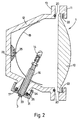
- an underwater light fitting comprises a housing generally designated 1, mounted in a niche 2 in the side wall of a pool, and a power transmission cable 3 running from a wall of the niche 2 to the housing 1.
- the power transmission cable 3 is provided with a wet-mateable connection 4, 5 between the wall of the niche 2 and the housing 1.
- connection alternatively called underwater mateable connections
- Such connections typically comprise at least one pair of terminals to be connected, one of the pair being provided on a pin and the other being provided in a socket. Insertion of the pin into the socket makes the connection by bringing the pair of terminals into contact with each other. The close fit of the pin in the socket expels water from the vicinity of the terminals.
- Such a connection can therefore be operated underwater, which in many circumstances is more convenient than making the connection in a dry environment, sealing it, and then moving it to the required, immersed location.
- such connections require the power to be disconnected while the pin is not inserted in the socket, since when this is the case, the terminals will not be isolated from the surrounding water.
- the housing 1 is shown in a slightly exploded manner in order that the individual elements may easily be seen.
- the housing 1 comprises a lens 10 at the front of the housing 1 which is attached, by means of a bezel 11, to a casing 12 which constitutes the rear and sides of the housing 1.
- a selected lens 10 rather than a plain glass face allows the degree of dispersion of illumination into the water to be selectively predetermined (although a plain glass face could be used).
- a seal preferably a recessed "O" ring 20, is provided in order to make the join between the lens 10 and the casing 12 water-tight and an additional seal 22 is provided between the bezel 11 and the lens 10.
- the casing 12 provides a flange 13 to which the bezel 11 is attached via known fixings such as nut and bolt assemblies (not shown).
- the lens 10 is attached by the bezel 11 to the casing 12 it remains in position, and although it may be removed in order to perform maintenance operations it need not be removed for routine bulb replacement. Standard fixings are therefore adequate even though their use might cause problems in a housing where they would be loosened and retightened each time a bulb needed to be replaced.
- the housing 1 contains a light source in the form of a bulb 14 to provide illumination and a (preferably diffusing) reflector 15, mounted on a reflector mounting block 23, to reflect illumination from the bulb 14 towards the lens 10 at the front of the housing 1. It is desirable to use a reflector and/or reflector mounting which can be arranged in one of several configurations. This allows the characteristics of the light projected from the housing to be selected according to, for example, the height above the pool bottom at which the light fitting is to be installed.
- the reflector 15 is attached to the reflector mounting block 23 (which is shown in Fig 5) by attachment means in the form of a screw 25 which passes through an aperture (not shown) in the reflector 15 and into one of a number of holes 26, 27, 28, 29, 30 provided in the mounting block 23.
- the part of the reflector 15 adjacent the screw 24 is thereby held in contact with a concave surface 24 of the mounting block 23.
- the holes 26, 27, 28, 29, 30 provided in the mounting block 23 are distributed so that the orientation of the reflector 15 relative to the casing 12 may be selected by selection of the hole via which the reflector 15 is attached to the mounting block 23.
- the bulb 14 is mounted on a connection assembly 16, and the bulb 14 and connection assembly 16 may be removed from the housing 1 (as will be described hereafter) in order to change the bulb.
- Fig 3 shows a detail of the casing 12 of the housing 1 and also shows the connection assembly 16 in detail.
- the connection assembly 16 is generally cylindrical and includes a central cylindrical bore through which a power transmission cable 3 passes from the exterior of the housing 1 to the interior, supplying power to the bulb 14.
- a permanent seal 33 is provided in order to prevent the ingress of water in which the housing 1 will, in use, be immersed.
- the seal 33 may be a potting material or gland or may comprise a waterproof sleeve or gaiter enclosing the interface between the cable 3 and the connector assembly 16.
- connection assembly 16 passes through a cylindrical bore defined by a shaped portion 34 of the casing 12.
- the generally cylindrical connection assembly 16 includes a flange 17 which, in use, is seated across the external end of the shaped portion 34 of the casing 12.
- a cap 31 is provided which secures the flange 17 of the connection assembly 16 to the shaped portion 34 of the casing 12.
- the cap 31 has an internally threaded portion 36 which engages an externally threaded portion 37 of the shaped portion 34 of the casing 12. The cap 31 thus screws onto the shaped portion 34, securing the flange 17 of the connection assembly 16 to the external end of the shaped portion 34 of the casing 12.
- An "O" ring 35 is provided between the flange 17 and the external end of the shaped portion 34, in order to prevent ingress of water. In use, therefore, the housing 1 is water-tight.
- the housing 1 is removed from the water in which it is, in use, immersed. In order to remove the housing from the water, the housing 1 is removed from the mountings (not shown) holding it in the niche 2. At this point it is still attached to the wall of the niche 2 by the power transmission cable 3. However, the housing 1 can be pulled a small distance out of the niche 2 and can then be detached from the rear wall of the niche 2 by separating the two elements 4, 5 of the wet-mateable connector which is provided in the power transmission cable 3. The housing 1 is thus completely freed of its connection to the niche 2 and may be removed not only from the water but also from the vicinity of the pool in which it was installed. The cap 31 is then unscrewed and removed from the shaped portion 34 of the casing 12.
- connection assembly 16 which is then withdrawn from the housing 1 along with the attached bulb 14.
- the bulb 14 may then be replaced (that is a new bulb may be connected to the connection assembly 16) and the new bulb 14 and the connection assembly 16 then inserted into the housing 1.
- the cap 31 is then screwed down onto the shaped portion 34 of the casing 12, securing the connection assembly 16 in place.
- the cap 31 is designed to be operable by hand, and using a suitable pitch of thread enables a large force to be applied to the sealed interface between the flange 17 of the connection assembly 16 and the external end of the shaped portion 34, of the casing 12. This force deforms the "O" ring provided between the flange 17 and the shaped portion 17 of the casing 12, forming a good seal.
- the "O” ring is recessed into the end of the shaped portion 34 of the casing 12.
- Such “O” rings are quite resilient and can be used many times without a significant reduction the efficiency of the seals formed. This resilience is due, in part, to the dimensions of the "O” ring.
- the diameter of an "O" ring suitable for use in the housing described might be between about one inch (2.5 cm) and two inches (5 cm), whilst the thickness (that is the diameter of the rubber element forming the ring) might be between about 0.2 inches (0.5 cm) to 0.3 inches (0.75 cm).
- a seal used between the casing and the glass face of a previously known housing might have a diameter of the order of 8 inches (20 cm) and a thickness of about 0.05 inches (0.1 cm).
- Fig 4 shows a cross section of part of an alternatively constructed casing 42, showing an appropriate shape and configuration for manufacture from a plastics material by an injection moulding process.
- the main part 40 of the casing 42 is manufactured by injection moulding, being so configured that moulding tools can form the required shape and then be withdrawn. (In this drawing this is illustrated by the fact that each part of the surface of the main part 40 has line of view to either the right or the left of the drawing which is unobstructed by any other part of the main part 40.)
- the additional part of the casing 45 which constitutes the shaped portion which, in use, houses the connection assembly 16 and to which the cap 31 attaches, can be manufactured separately out of a suitable material, and then attached to the main part 40 of the casing 42.
- the wet-mateable connection 4,5 in the cable 3 enables the housing 1 to be easily disconnected from the niche 2. This means that maintenance may be performed in any convenient location, rather than being limited to the poolside.
- the length of cable 3 needed is much smaller (since it need not reach from the niche 2 to the poolside) than in previous fittings. This allows greater circulation of water in the niche 2, enhancing the cooling of the housing 1. This prolongs the life of components in the housing 1, such as the cable 3 and the bulb 14, and may allow less specialised, cheaper bulbs to be used.
- Removing and replacing the bulb 14 via the relatively small opening created by removal of the cap 31, rather than via the large opening created by removal of the lens 10 from the front of the housing 1, means that only this small opening need be regularly unsealed and resealed. This avoids the difficult removal of the front lens 10, and consequent disturbance of, or damage to, the more easily damaged seals around the lens. Damage to fixings resulting from regular refastening and possible over-tightening of the bezel is avoided, and the use of expensive modular units to overcome these problems is rendered unnecessary.
- screw cap 31 also means that replacement of the bulb 14 may be executed without the use of tools to gain access to the interior of the housing 1.
- the mountings provided to mount the housing 1 into the niche 2 may, however, be of the type that can only be operated using tools, in order to reduce the chance of unauthorised persons demounting the housing.
- the whole housing may be replaced by merely connecting a new housing to the cable 3 in the wall of the niche 2 via the wet-mateable connector 4,5 and mounting the new housing in the niche 2.
- the cable between the niche wall and the wet-mateable connector is not damaged by normal operation of the light fitting and therefore does not need to be routinely replaced. This avoids the need for the expensive and time consuming operation of draining the pool.
- Underwater light fittings according to the present invention may be suitable for many uses in addition to swimming pool and spa bath use.
- such fittings may be used in beer vats or in the hulls of boats or in many other circumstances where niche mounted underwater light fittings are required.
- the combination of bezel 11, seal 22 and lens 10 could be replaced by a modular unit of a suitable material (such as, for example, heat resistant polycarbonate).
- a modular unit could include a light transmissive portion, corresponding in use to the lens of the illustrated embodiment, surrounded by a frosted or coloured portion, corresponding in use to the bezel of the illustrated embodiment. Use of such a modular unit would further simplify assembly and maintenance of the light fitting.
- the reflector mounting block shown as having the shape of a truncated pyramid, could alternatively be of cylindrical or frustoconical shape, and could be made from a thermally conductive material in order to provide a heat sink.
- the reflector configuration could be altered by selectively orientating flaps or panels provided on the reflective surface of the reflector.
Landscapes
- Engineering & Computer Science (AREA)
- General Engineering & Computer Science (AREA)
- Arrangement Of Elements, Cooling, Sealing, Or The Like Of Lighting Devices (AREA)
- Mechanical Coupling Of Light Guides (AREA)
- Glass Compositions (AREA)
- Liquid Crystal Substances (AREA)
- Instruments For Viewing The Inside Of Hollow Bodies (AREA)
Claims (13)
- Eine Unterwasserleuchte zum Einbau in eine Nische, bestehend aus:einem Gehäuse (1), bestehend aus einem wasserdichten Gehäusekörper (12) mit einem Rückenteil und seitlichen Teilen, die ausgeführt sind, um in eine Nische zu passen, einem lichtdurchlässigen Teil und einer Eingangsöffnung zum Einführen einer Stromzufuhrvorrichtung (3) in das Gehäuse (1), wobei die Eingangsöffnung eine wasserundurchlässige Dichtung aufweist;einer Montagevorrichtung für die abnehmbare Montage des Gehäuses (1) in einer Nische (2) in einer Wand oder einer anderen Fläche;einer Stromzufuhrvorrichtung (3), die ausgeführt ist, um von einer Stromquelle zu einer Lichtquelle innerhalb des Gehäuses (1) zu führen;und wobei der wasserdichte Gehäusekörper (12) einen abnehmbaren Teil (31) beinhaltet, der vorübergehend vom übrigen Gehäusekörper (12) entfernt werden kann, wodurch die Lichtquelle aus dem Gehäuse (1) entfernt werden kann;dadurch gekennzeichnet, daß die Unterwasserleuchte weiters einen Anschlußstecker für eine Verbindung im Wasser (4, 5) in der Stromzufuhrvorrichtung (3) beinhaltet; und die Eingangsöffnung sich im Rückenteil des Gehäusekörpers (12) befindet.
- Unterwasserleuchte gemäß Anspruch 1, wobei eine Dichtung (35) bereitgestellt wird, um das Eindringen von Wasser durch die Fuge zwischen dem abnehmbaren Teil des Gehäusekörpers (31) und dem übrigen Gehäusekörper (12) in das Gehäuse (1) zu verhindern.
- Unterwasserleuchte gemäß Anspruch 2, wobei die Dichtung ein O-Ring (35) ist.
- Unterwasserleuchte gemäß Anspruch 1, wobei der abnehmbare Teil (31) des Gehäusekörpers eine Kappe mit einem im wesentlichen zylindrischen Teil mit einem Glasgewinde (36) umfaßt, die ausgeführt ist, um in einen Teil des übrigen Gehäusekörpers (12) einzugreifen, der ein entsprechendes Gewinde aufweist.
- Unterwasserleuchte gemäß Anspruch 2 oder 3, wobei ein Verbindungsteil (16) bereitgestellt wird, der bei Gebrauch an die Lichtquelle innerhalb des Gehäuses (1) angeschlossen wird, wobei ein Teil davon zwischen einen Abschnitt des abnehmbaren Teils (31) des Gehäusekörpers und einen Abschnitt des übrigen Gehäusekörpers (12) hineinragt.
- Unterwasserleuchte gemäß Anspruch 5, wobei die Dichtung (35) sich zwischen dem Verbindungsteil (16) und dem Gehäusekörper (12) befindet und die Dichtung (35) zusammengepreßt werden kann, indem die Kappe (31) auf den übrigen Gehäusekörper (12) geschraubt wird.
- Unterwasserleuchte gemäß Anspruch 1, wobei die Stromzufuhrvorrichtung (3) ein Elektrokabel ist.
- Unterwasserleuchte gemäß Anspruch 1, wobei ein wesentlicher Teil des wasserdichten Gehäusekörpers (12) aus einem Kunststoffmaterial hergestellt ist.
- Unterwasserleuchte gemäß Anspruch 8, wobei ein wesentlicher Teil des wasserdichten Gehäusekörpers (12) mit Hilfe eines Spritzgießverfahrens hergestellt wird.
- Unterwasserleuchte gemäß Anspruch 1, wobei Vorrichtungen bereitgestellt werden, durch die Wasser in die Nische (2) gelangen kann, wenn das Gehäuse (1) in der Nische (2) montiert ist.
- Unterwasserleuchte gemäß Anspruch 1, wobei ein Reflektor zwischen der Lichtquelle und zumindest einem Teil des Gehäusekörpers (12) bereitgestellt wird, und wobei der Reflektor verstellbar ist, um die Reflexionseigenschaften zu verändern.
- Unterwasserleuchte gemäß Anspruch 1, wobei der lichtdurchlässige Teil des Gehäuses (1) eine Sammellinse oder eine Zerstreuungslinse (10) umfaßt.
- Unterwasserleuchte gemäß Anspruch 12, wobei der lichtdurchlässige Teil des Gehäuses (1) eine Fresnel-Linse (10) umfaßt.
Applications Claiming Priority (3)
| Application Number | Priority Date | Filing Date | Title |
|---|---|---|---|
| GB9410401A GB9410401D0 (en) | 1994-05-24 | 1994-05-24 | Underwater light fitting |
| GB9410401 | 1994-05-24 | ||
| PCT/GB1995/001159 WO1995032388A1 (en) | 1994-05-24 | 1995-05-22 | Underwater light fitting |
Publications (2)
| Publication Number | Publication Date |
|---|---|
| EP0760921A1 EP0760921A1 (de) | 1997-03-12 |
| EP0760921B1 true EP0760921B1 (de) | 1999-12-01 |
Family
ID=10755642
Family Applications (1)
| Application Number | Title | Priority Date | Filing Date |
|---|---|---|---|
| EP95919531A Expired - Lifetime EP0760921B1 (de) | 1994-05-24 | 1995-05-22 | Unterwasserleuchte |
Country Status (8)
| Country | Link |
|---|---|
| US (1) | US5800041A (de) |
| EP (1) | EP0760921B1 (de) |
| AT (1) | ATE187235T1 (de) |
| AU (1) | AU2531795A (de) |
| DE (1) | DE69513654T2 (de) |
| ES (1) | ES2143631T3 (de) |
| GB (2) | GB9410401D0 (de) |
| WO (1) | WO1995032388A1 (de) |
Families Citing this family (33)
| Publication number | Priority date | Publication date | Assignee | Title |
|---|---|---|---|---|
| US5842771A (en) * | 1995-11-03 | 1998-12-01 | American Products, Inc. | Submersible light fixture |
| US7482764B2 (en) * | 1997-08-26 | 2009-01-27 | Philips Solid-State Lighting Solutions, Inc. | Light sources for illumination of liquids |
| GB9825147D0 (en) | 1998-11-18 | 1999-01-13 | Aqua Pharos Int Ltd | Disposable underwater light fitting |
| EP1083384A1 (de) * | 1999-09-10 | 2001-03-14 | Certikin International Ltd | Halogenleuchteneinheit |
| US6315424B1 (en) * | 2000-01-24 | 2001-11-13 | Smartpool Incorporated | Underwater safety lighting device for swimming pools |
| US7204602B2 (en) * | 2001-09-07 | 2007-04-17 | Super Vision International, Inc. | Light emitting diode pool assembly |
| GB0228712D0 (en) * | 2002-12-10 | 2003-01-15 | Aqua Pharos Internat Ltd | Underwater pool light |
| US6942354B2 (en) * | 2003-03-21 | 2005-09-13 | 9090-3493 Quebec Inc. | Lighting system and housing therefore |
| DE102004008155A1 (de) * | 2003-10-02 | 2005-08-25 | Sebastian Schmitt | Freizeitplattform auf Wasseroberflächen mit Erhitzungsmöglichkeit für Lebensmittel |
| WO2005036051A2 (en) * | 2003-10-09 | 2005-04-21 | Smartpool, Inc. | Underwater light for soft-sided aboveground pools |
| US7044623B2 (en) * | 2003-11-21 | 2006-05-16 | Deepsea Power & Light | Thru-hull light |
| GB2413840B (en) * | 2004-05-07 | 2006-06-14 | Savage Marine Ltd | Underwater lighting |
| EP1653255A3 (de) * | 2004-10-29 | 2006-06-21 | Pentair Water Pool and Spa, Inc. | Linse mit einstellbarem Strahl für Unterwasserlicht |
| DE602006008440D1 (de) * | 2005-03-08 | 2009-09-24 | Carl Denis Amor | |
| US20070137544A1 (en) * | 2005-09-09 | 2007-06-21 | Macdonald Ian M | Two piece view port and light housing |
| US7705240B2 (en) * | 2005-10-27 | 2010-04-27 | Pentair Water Pool And Spa, Inc. | Cord seal for swimming pool and spa light niches |
| US20080130304A1 (en) * | 2006-09-15 | 2008-06-05 | Randal Rash | Underwater light with diffuser |
| WO2008066619A1 (en) * | 2006-10-19 | 2008-06-05 | Travis Sparks | Pool light with safety alarm and sensor array |
| US7520644B2 (en) * | 2006-12-28 | 2009-04-21 | Robert Jordan | Transom drain light |
| US8016463B2 (en) * | 2006-12-28 | 2011-09-13 | Tojo Sea Below, Llc | Transom drain light |
| US7591564B1 (en) * | 2007-08-28 | 2009-09-22 | Ball Bradley A | Underwater lighting system |
| US7740368B2 (en) * | 2008-01-08 | 2010-06-22 | Ming Chiang | Cap with a light emitting diode (LED) for illuminating a beverage container |
| JP5555180B2 (ja) * | 2008-01-16 | 2014-07-23 | ライツ、 キャメラ、 アクション エルエルシイ | 水中使用可能な高照度光源アセンブリー |
| US20100002435A1 (en) * | 2008-07-01 | 2010-01-07 | Underwater Lights Usa, Llc | Led light with a diffracting lens |
| US8292449B2 (en) * | 2009-07-24 | 2012-10-23 | Remote Ocean Systems, Inc. | Modular lamp for illuminating a hazardous underwater environment |
| US9109766B1 (en) * | 2014-02-25 | 2015-08-18 | Bradley A. Ball | Underwater lighting system |
| US10077896B2 (en) | 2015-09-14 | 2018-09-18 | Trent Neil Butcher | Lighting devices including at least one light-emitting device and systems including at least one lighting device |
| KR102450557B1 (ko) * | 2015-11-12 | 2022-10-05 | 엘지이노텍 주식회사 | 카메라 모듈 |
| US10125967B2 (en) * | 2016-08-24 | 2018-11-13 | Henry Lockard | Underwater light cover kit |
| US10571096B2 (en) | 2018-02-15 | 2020-02-25 | Abl Ip Holding Llc | Light fixture with accessible electronics housing |
| US10933959B2 (en) * | 2019-02-28 | 2021-03-02 | Research & Design Innovations, Llc | Angled light |
| USD986448S1 (en) * | 2019-07-02 | 2023-05-16 | Research And Design Innovations, Llc | Deck light |
| US11287096B1 (en) * | 2019-09-09 | 2022-03-29 | Research & Design Innovations, Llc | Deck light |
Family Cites Families (13)
| Publication number | Priority date | Publication date | Assignee | Title |
|---|---|---|---|---|
| US1968072A (en) * | 1929-07-12 | 1934-07-31 | R U V Company | Under water lighting unit |
| US1806435A (en) * | 1929-09-26 | 1931-05-19 | Westinghouse Electric & Mfg Co | Lighting unit |
| FR763047A (fr) * | 1933-01-16 | 1934-04-23 | Lumi Or | Appareil pour l'éclairage de l'eau des piscines et bassins |
| US4156894A (en) * | 1975-11-04 | 1979-05-29 | Dega Proprietary Limited | Light fitting |
| DE7815805U1 (de) * | 1978-05-26 | 1978-09-21 | K.-F. Schlack Betonsteinwerk- Springbrunnenbau, 4930 Detmold | Wasserdichter scheinwerfer |
| US4290094A (en) * | 1980-04-14 | 1981-09-15 | Henning Jensen | Underwater or weatherproof light |
| US4574337A (en) * | 1984-02-10 | 1986-03-04 | Gty Industries | Underwater lights |
| US4539629A (en) * | 1984-02-10 | 1985-09-03 | Gty Industries | Spa light |
| GB2178603A (en) * | 1985-07-30 | 1987-02-11 | Birns Oceanographics | Electrical connector for underwater mating |
| US5045978A (en) * | 1989-06-05 | 1991-09-03 | Gargle Benjamin H | Underwater lighting fixture |
| DE8910902U1 (de) * | 1989-09-12 | 1990-02-01 | OASE-PUMPEN Wübker Söhne GmbH & Co. Maschinenfabrik, 48477 Hörstel | Elektrisches Unterwassergerät, insbesondere Leuchte |
| US4996635A (en) * | 1989-10-13 | 1991-02-26 | Deepsea Power & Light, Inc. | Deep submersible light assembly with dry pressure dome |
| US5105346A (en) * | 1990-09-10 | 1992-04-14 | Remote Ocean Systems, Inc. | Method and apparatus for illuminating an underwater environment |
-
1994
- 1994-05-24 GB GB9410401A patent/GB9410401D0/en active Pending
-
1995
- 1995-05-20 US US08/737,969 patent/US5800041A/en not_active Expired - Lifetime
- 1995-05-22 AU AU25317/95A patent/AU2531795A/en not_active Abandoned
- 1995-05-22 EP EP95919531A patent/EP0760921B1/de not_active Expired - Lifetime
- 1995-05-22 ES ES95919531T patent/ES2143631T3/es not_active Expired - Lifetime
- 1995-05-22 WO PCT/GB1995/001159 patent/WO1995032388A1/en not_active Ceased
- 1995-05-22 DE DE69513654T patent/DE69513654T2/de not_active Expired - Fee Related
- 1995-05-22 GB GB9623391A patent/GB2302400B/en not_active Expired - Lifetime
- 1995-05-22 AT AT95919531T patent/ATE187235T1/de not_active IP Right Cessation
Also Published As
| Publication number | Publication date |
|---|---|
| EP0760921A1 (de) | 1997-03-12 |
| GB2302400A (en) | 1997-01-15 |
| US5800041A (en) | 1998-09-01 |
| ATE187235T1 (de) | 1999-12-15 |
| GB9623391D0 (en) | 1997-01-08 |
| AU2531795A (en) | 1995-12-18 |
| DE69513654T2 (de) | 2003-05-08 |
| GB9410401D0 (en) | 1994-07-13 |
| GB2302400B (en) | 1998-05-27 |
| ES2143631T3 (es) | 2000-05-16 |
| DE69513654D1 (de) | 2000-01-05 |
| WO1995032388A1 (en) | 1995-11-30 |
Similar Documents
| Publication | Publication Date | Title |
|---|---|---|
| EP0760921B1 (de) | Unterwasserleuchte | |
| EP1861652B1 (de) | Led-beleuchtungsgerät in einem kunststoffgehäuse | |
| US4782430A (en) | Light conduit illumination system for underwater lighting | |
| US8292449B2 (en) | Modular lamp for illuminating a hazardous underwater environment | |
| EP1742834B1 (de) | Unterwasserbeleuchtung | |
| US20100002435A1 (en) | Led light with a diffracting lens | |
| US7188378B2 (en) | Swimming pool immersed light fixture | |
| US5105346A (en) | Method and apparatus for illuminating an underwater environment | |
| US5508894A (en) | Boat trailer light assembly | |
| US7373894B2 (en) | Window housing for use with thru-hull fittings | |
| US6398397B1 (en) | Fiber optic pool lighting apparatus | |
| US5386355A (en) | Method and apparatus for illuminating a hazardous underwater environment | |
| US4644450A (en) | Lighting unit for liquids | |
| US7520644B2 (en) | Transom drain light | |
| US7364323B2 (en) | Pool light mounting system | |
| US5213410A (en) | Method and apparatus for illuminating an underwater environment | |
| US8016463B2 (en) | Transom drain light | |
| US10859214B2 (en) | Apparatus and methods for retrofitting incandescent luminaire fixtures principally for use in swimming pools and spas | |
| KR200293888Y1 (ko) | 수중 조명등 | |
| US3364347A (en) | Lamp housing lens | |
| CN215951268U (zh) | 泳池漂浮灯 | |
| WO2000029782A1 (en) | Disposable underwater light fitting | |
| CN220749880U (zh) | 一种深海照明灯具 | |
| BR202017004913Y1 (pt) | Refletor subaquático para piscinas e fontes | |
| GB2339892A (en) | An underwater halogen lamp assembly |
Legal Events
| Date | Code | Title | Description |
|---|---|---|---|
| PUAI | Public reference made under article 153(3) epc to a published international application that has entered the european phase |
Free format text: ORIGINAL CODE: 0009012 |
|
| 17P | Request for examination filed |
Effective date: 19961120 |
|
| AK | Designated contracting states |
Kind code of ref document: A1 Designated state(s): AT BE CH DE ES FR GB GR IT LI PT SE |
|
| RBV | Designated contracting states (corrected) |
Designated state(s): AT BE CH DE ES FR GB GR IT LI PT SE |
|
| 17Q | First examination report despatched |
Effective date: 19980107 |
|
| GRAG | Despatch of communication of intention to grant |
Free format text: ORIGINAL CODE: EPIDOS AGRA |
|
| GRAG | Despatch of communication of intention to grant |
Free format text: ORIGINAL CODE: EPIDOS AGRA |
|
| GRAH | Despatch of communication of intention to grant a patent |
Free format text: ORIGINAL CODE: EPIDOS IGRA |
|
| GRAH | Despatch of communication of intention to grant a patent |
Free format text: ORIGINAL CODE: EPIDOS IGRA |
|
| GRAA | (expected) grant |
Free format text: ORIGINAL CODE: 0009210 |
|
| AK | Designated contracting states |
Kind code of ref document: B1 Designated state(s): AT BE CH DE ES FR GB GR IT LI PT SE |
|
| PG25 | Lapsed in a contracting state [announced via postgrant information from national office to epo] |
Ref country code: LI Free format text: LAPSE BECAUSE OF FAILURE TO SUBMIT A TRANSLATION OF THE DESCRIPTION OR TO PAY THE FEE WITHIN THE PRESCRIBED TIME-LIMIT Effective date: 19991201 Ref country code: GR Free format text: LAPSE BECAUSE OF NON-PAYMENT OF DUE FEES Effective date: 19991201 Ref country code: CH Free format text: LAPSE BECAUSE OF FAILURE TO SUBMIT A TRANSLATION OF THE DESCRIPTION OR TO PAY THE FEE WITHIN THE PRESCRIBED TIME-LIMIT Effective date: 19991201 Ref country code: BE Free format text: LAPSE BECAUSE OF FAILURE TO SUBMIT A TRANSLATION OF THE DESCRIPTION OR TO PAY THE FEE WITHIN THE PRESCRIBED TIME-LIMIT Effective date: 19991201 Ref country code: AT Free format text: LAPSE BECAUSE OF FAILURE TO SUBMIT A TRANSLATION OF THE DESCRIPTION OR TO PAY THE FEE WITHIN THE PRESCRIBED TIME-LIMIT Effective date: 19991201 |
|
| REF | Corresponds to: |
Ref document number: 187235 Country of ref document: AT Date of ref document: 19991215 Kind code of ref document: T |
|
| REG | Reference to a national code |
Ref country code: CH Ref legal event code: EP |
|
| REF | Corresponds to: |
Ref document number: 69513654 Country of ref document: DE Date of ref document: 20000105 |
|
| ITF | It: translation for a ep patent filed | ||
| PG25 | Lapsed in a contracting state [announced via postgrant information from national office to epo] |
Ref country code: PT Free format text: LAPSE BECAUSE OF FAILURE TO SUBMIT A TRANSLATION OF THE DESCRIPTION OR TO PAY THE FEE WITHIN THE PRESCRIBED TIME-LIMIT Effective date: 20000302 |
|
| ET | Fr: translation filed | ||
| REG | Reference to a national code |
Ref country code: ES Ref legal event code: FG2A Ref document number: 2143631 Country of ref document: ES Kind code of ref document: T3 |
|
| PG25 | Lapsed in a contracting state [announced via postgrant information from national office to epo] |
Ref country code: GB Free format text: LAPSE BECAUSE OF NON-PAYMENT OF DUE FEES Effective date: 20000522 |
|
| REG | Reference to a national code |
Ref country code: CH Ref legal event code: PL |
|
| PLBE | No opposition filed within time limit |
Free format text: ORIGINAL CODE: 0009261 |
|
| STAA | Information on the status of an ep patent application or granted ep patent |
Free format text: STATUS: NO OPPOSITION FILED WITHIN TIME LIMIT |
|
| 26N | No opposition filed | ||
| GBPC | Gb: european patent ceased through non-payment of renewal fee |
Effective date: 20000522 |
|
| PGFP | Annual fee paid to national office [announced via postgrant information from national office to epo] |
Ref country code: SE Payment date: 20090514 Year of fee payment: 15 Ref country code: IT Payment date: 20090528 Year of fee payment: 15 Ref country code: FR Payment date: 20090513 Year of fee payment: 15 Ref country code: DE Payment date: 20090525 Year of fee payment: 15 |
|
| EUG | Se: european patent has lapsed | ||
| REG | Reference to a national code |
Ref country code: FR Ref legal event code: ST Effective date: 20110131 |
|
| PG25 | Lapsed in a contracting state [announced via postgrant information from national office to epo] |
Ref country code: IT Free format text: LAPSE BECAUSE OF NON-PAYMENT OF DUE FEES Effective date: 20100522 Ref country code: SE Free format text: LAPSE BECAUSE OF NON-PAYMENT OF DUE FEES Effective date: 20100523 |
|
| PG25 | Lapsed in a contracting state [announced via postgrant information from national office to epo] |
Ref country code: DE Free format text: LAPSE BECAUSE OF NON-PAYMENT OF DUE FEES Effective date: 20101201 |
|
| PG25 | Lapsed in a contracting state [announced via postgrant information from national office to epo] |
Ref country code: FR Free format text: LAPSE BECAUSE OF NON-PAYMENT OF DUE FEES Effective date: 20100531 |
|
| PGFP | Annual fee paid to national office [announced via postgrant information from national office to epo] |
Ref country code: ES Payment date: 20140523 Year of fee payment: 20 |
|
| REG | Reference to a national code |
Ref country code: ES Ref legal event code: FD2A Effective date: 20150729 |
|
| PG25 | Lapsed in a contracting state [announced via postgrant information from national office to epo] |
Ref country code: ES Free format text: LAPSE BECAUSE OF EXPIRATION OF PROTECTION Effective date: 20150523 |