EP0761033B2 - Verfahren zur befestigung von leiterstäben - Google Patents
Verfahren zur befestigung von leiterstäben Download PDFInfo
- Publication number
- EP0761033B2 EP0761033B2 EP95918453A EP95918453A EP0761033B2 EP 0761033 B2 EP0761033 B2 EP 0761033B2 EP 95918453 A EP95918453 A EP 95918453A EP 95918453 A EP95918453 A EP 95918453A EP 0761033 B2 EP0761033 B2 EP 0761033B2
- Authority
- EP
- European Patent Office
- Prior art keywords
- elastomer
- groove
- bar
- interlaced
- conductive
- Prior art date
- Legal status (The legal status is an assumption and is not a legal conclusion. Google has not performed a legal analysis and makes no representation as to the accuracy of the status listed.)
- Expired - Lifetime
Links
- 238000000034 method Methods 0.000 title claims abstract description 23
- 229920001971 elastomer Polymers 0.000 claims abstract description 56
- 239000000806 elastomer Substances 0.000 claims abstract description 56
- 238000004804 winding Methods 0.000 claims abstract description 14
- 239000000463 material Substances 0.000 claims abstract 2
- 238000009423 ventilation Methods 0.000 claims description 10
- 238000002347 injection Methods 0.000 claims description 3
- 239000007924 injection Substances 0.000 claims description 3
- 229920003023 plastic Polymers 0.000 claims description 2
- 239000004033 plastic Substances 0.000 claims description 2
- 238000001816 cooling Methods 0.000 abstract description 13
- 239000003292 glue Substances 0.000 abstract description 2
- 238000003475 lamination Methods 0.000 abstract 3
- 239000004020 conductor Substances 0.000 description 14
- 239000010410 layer Substances 0.000 description 8
- 230000006855 networking Effects 0.000 description 4
- 230000017525 heat dissipation Effects 0.000 description 3
- 239000000853 adhesive Substances 0.000 description 2
- 230000001070 adhesive effect Effects 0.000 description 2
- 230000000694 effects Effects 0.000 description 2
- 238000003825 pressing Methods 0.000 description 2
- 238000009736 wetting Methods 0.000 description 2
- 238000001266 bandaging Methods 0.000 description 1
- 230000015572 biosynthetic process Effects 0.000 description 1
- 239000000969 carrier Substances 0.000 description 1
- 239000012876 carrier material Substances 0.000 description 1
- 150000001875 compounds Chemical class 0.000 description 1
- 229920006037 cross link polymer Polymers 0.000 description 1
- 238000011161 development Methods 0.000 description 1
- 230000018109 developmental process Effects 0.000 description 1
- 239000003063 flame retardant Substances 0.000 description 1
- 239000011888 foil Substances 0.000 description 1
- 239000003365 glass fiber Substances 0.000 description 1
- 229920000642 polymer Polymers 0.000 description 1
- 239000011241 protective layer Substances 0.000 description 1
- 229920002379 silicone rubber Polymers 0.000 description 1
- 239000004945 silicone rubber Substances 0.000 description 1
- 239000007921 spray Substances 0.000 description 1
- 230000008646 thermal stress Effects 0.000 description 1
Images


Classifications
-
- H—ELECTRICITY
- H02—GENERATION; CONVERSION OR DISTRIBUTION OF ELECTRIC POWER
- H02K—DYNAMO-ELECTRIC MACHINES
- H02K3/00—Details of windings
- H02K3/32—Windings characterised by the shape, form or construction of the insulation
- H02K3/40—Windings characterised by the shape, form or construction of the insulation for high voltage, e.g. affording protection against corona discharges
-
- H—ELECTRICITY
- H02—GENERATION; CONVERSION OR DISTRIBUTION OF ELECTRIC POWER
- H02K—DYNAMO-ELECTRIC MACHINES
- H02K3/00—Details of windings
- H02K3/46—Fastening of windings on the stator or rotor structure
- H02K3/48—Fastening of windings on the stator or rotor structure in slots
Definitions
- the invention relates to a method for fastening conductor bars, in particular high-voltage windings of electrical machines in grooves of the laminated cores provided with ventilation slots, in which the conductor bars are glued to the groove with an electrically conductive cross-linked elastomer, the uncrosslinked elastomer being introduced into the groove as a soft mass, embedded in this, supplemented on the rod side of the elastomer facing the groove opening and the conductor rod is fixed until the elastomer crosslinks.
- DE-A1-4 025 439 also describes an arrangement with winding carriers and winding bars, in which between each slot wall and a bar edge of the winding bar there is a filling made of a rubber-elastic, electrically conductive mass, in order to provide mechanically and electrically highly loadable connections between the protective layer of the winding rod and the slot walls is created so that the formation of glow discharges and sparks in the slot can be practically excluded.
- the winding rod is preferably fixed in this arrangement by means of a leaf spring acting between the slot wedge and the top of the rod.
- the object of the invention is. a procedure of the beginning cited way of creating the winding is permanently and securely attached or in vertical Machines safely prevent the winding from sinking becomes.
- the method according to the invention is characterized in that that the elastomer about in the middle of the partial package at the bottom of the groove, and on dosed on the top of the rod and on the intermediate piece is introduced, the distribution of the elastomer by pressing in the conductor rod or Intermediate piece and possibly the key takes place that at the bottom of the groove or at the bottom of the groove parallel surfaces a predominantly closed one Elastomer layer results and the elastomer layer spreads on the groove flanks.
- the elastomer inserted into the groove.
- the width of the injector is matched to the groove width and has two Opening openings.
- the prepared grooves are inserted the elastomer introduced in the middle of the package. So it becomes the amount of elastomer in drops in each edge groove base - groove flank through the outlet openings placed the dosing device.
- the bottom rods are pressed into the grooves that the elastomer adheres to the base of the groove and partially the groove flanks, but not in the ventilation slots is pressed. Pushing in the ladder bars but does not require balanced centering or special Distances.
- top bars are attached in the same way as Bottom bar attachment. But before that the elastomer on the surface of the top bar facing the slot opening is dosed, the slot wedge is inserted.
- the slot wedge is injection molded and has one fire-retardant, glass fiber reinforced version.
- the slot wedge has the key in the middle of a hole through which a needle dosing device under the elastomer Pressure is introduced. It is preferably 6 bar pressed in until the elastomer in the ventilation slot area becomes visible ..
- the air gap is therefore with a Provide louvre cover.
- the invention is a plastic Injection molded part.
- louver cover is the cooling effect insignificantly lower in the air gap, through which continuous, complete wetting of the conductor rod however, is an excellent heat transfer given from rod surface to laminated core.
- the achieved better heat transfer is much like the reduced one Cooling effect, so that in total one higher heat dissipation is achieved.
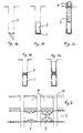
- the invention is based on exemplary embodiments. which are shown in the drawing, explained in more detail.
- La to le shows the first process steps 2 shows the spread of the elastomer layer
- Fig. 3 the pressing of the elastomer mass by means of Needle metering device
- Fig. 4 the attachment a conductor bar of a turbogenerator.
- the elastomer mass increases 9 when pushing the lower rods 3 up or when inserting the intermediate pieces 7, the elastomer mass flows towards the center of the ladder.
- the louvers 10 of the subpackages 11 do not drain any elastomers. So there is no narrowing of the cooling cross-section.
- the partial packages 15 a such laminated core have an unfavorable Ratio of package width to groove height.
- a poor heat transfer from Conductor rod 16 may be given if after the previously shown Procedure the ladder bars would be attached.
- create louvre covers 17 are provided.
- the louver covers 17 hardly reduce the cooling cross section. Extend into the cooling cross-section also the fan bars 21. By attaching these Louvre covers 17 can on the corners Groove base - groove flank and their corresponding one Elastomer strand are metered.
Landscapes
- Engineering & Computer Science (AREA)
- Power Engineering (AREA)
- Manufacture Of Motors, Generators (AREA)
- Insulation, Fastening Of Motor, Generator Windings (AREA)
- Particle Accelerators (AREA)
- Ladders (AREA)
- Coils Of Transformers For General Uses (AREA)
- Insulating Bodies (AREA)
- Forging (AREA)
- Conductive Materials (AREA)
- Non-Insulated Conductors (AREA)
Description
Claims (4)
- Verfahren zur Befestigung von Leiterstäben (3, 8, 16), insbesondere von Hochspannungswicklungen elektrischer Maschinen, in Nuten (1) der mit Lüftungsschlitzen (10) versehenen Blechpakete, bei dem die Leiterstäbe (3, 8, 16) mit einem elektrisch leitfähigen, vernetzten Elastomer mit der Nut verklebt wird, wobei das unvernetzte Elastomer als weiche Masse in die Nut (1) eingebracht, in dieses unvernetzte Elastomer der Leiterstab eingebettet, auf der zur Nutöffnung weisenden Stabseite das Elastomer ergänzt und der Leiterstab bis zum Vernetzen des Elastomers fixiert wird, dadurch gekennzeichnet, daß das Elastomer etwa in der Teilpaketmitte am Nutgrund und auf der Staboberseite und am Zwischenstück dosiert eingebracht wird, wobei die Verteilung des Elastomers durch das Eindrücken des Leiterstabes (3, 8, 16) bzw. des Zwischenstückes und gegebenenfalls des Nutkeiles (12) so erfolgt, daß am Nutgrund bzw. an den zum Nutgrund parallelen Flächen sich eine vorwiegend geschlossene Elastomerschicht ergibt und die Elastomerschicht sich an den beiden Nutflanken ausbreitet.
- Verfahren nach Anspruch 1, dadurch gekennzeichnet, daß vor der abschließenden Einbringung der Elastomerschicht ein Nutkeil (12) vorgesehen wird, der mittig eine Bohrung (13) aufweist, durch die mittels einer Nadeldosiervorrichtung das Elastomer unter Druck eingebracht wird.
- Verfahren nach Anspruch 1 oder 2, insbesondere für eine Hochleistungsmaschine, die schmale und hohe Teilpakete aufweist, dadurch gekennzeichnet, daß die Lüftungsschlitze (10) zwischen den Teilpaketen mit Luftschlitzabdeckungen (17) versehen sind.
- Verfahren nach Anspruch 3, dadurch gekennzeichnet, daß die Luftschlitzabdeckungen (17) ein aus Kunststoff bestehendes Spritzgussteil sind.
Applications Claiming Priority (4)
| Application Number | Priority Date | Filing Date | Title |
|---|---|---|---|
| AT0105294A AT403974B (de) | 1994-05-24 | 1994-05-24 | Verfahren zur befestigung von leiterstäben |
| AT105294 | 1994-05-24 | ||
| AT1052/94 | 1994-05-24 | ||
| PCT/AT1995/000098 WO1995032540A1 (de) | 1994-05-24 | 1995-05-23 | Verfahren zur befestigung von leiterstäben |
Publications (3)
| Publication Number | Publication Date |
|---|---|
| EP0761033A1 EP0761033A1 (de) | 1997-03-12 |
| EP0761033B1 EP0761033B1 (de) | 1998-06-17 |
| EP0761033B2 true EP0761033B2 (de) | 2001-08-01 |
Family
ID=3505551
Family Applications (1)
| Application Number | Title | Priority Date | Filing Date |
|---|---|---|---|
| EP95918453A Expired - Lifetime EP0761033B2 (de) | 1994-05-24 | 1995-05-23 | Verfahren zur befestigung von leiterstäben |
Country Status (10)
| Country | Link |
|---|---|
| US (1) | US5851340A (de) |
| EP (1) | EP0761033B2 (de) |
| JP (1) | JP3661947B2 (de) |
| CN (1) | CN1078969C (de) |
| AT (2) | AT403974B (de) |
| AU (1) | AU2439195A (de) |
| CA (1) | CA2190863C (de) |
| DE (1) | DE59502604D1 (de) |
| ES (1) | ES2119438T5 (de) |
| WO (1) | WO1995032540A1 (de) |
Families Citing this family (4)
| Publication number | Priority date | Publication date | Assignee | Title |
|---|---|---|---|---|
| US6453545B1 (en) * | 2000-12-06 | 2002-09-24 | General Electric Company | Compact inflatable device for applying localized pressure to turbine generator armature bars |
| GB0223487D0 (en) * | 2002-10-09 | 2002-11-13 | Alstom Switzerland Ltd | Armature bar mounting |
| FR2987907B1 (fr) | 2012-03-08 | 2014-02-21 | Saint Gobain | Valve optique et son procede de fabrication |
| KR20250078529A (ko) * | 2023-06-23 | 2025-06-02 | 지멘스 에너지, 인코포레이티드 | 수지 주입 장치 및 그 사용 방법 |
Citations (4)
| Publication number | Priority date | Publication date | Assignee | Title |
|---|---|---|---|---|
| DE2506790A1 (de) † | 1974-02-18 | 1975-08-21 | Gen Electric Canada | Kern- und spulen-struktur fuer dynamomaschinen und verfahren zur herstellung derselben |
| US4095627A (en) † | 1975-03-07 | 1978-06-20 | Canadian General Electric Company | Corona inhibition in dynamoelectric machines |
| CH658956A5 (en) † | 1983-06-16 | 1986-12-15 | Bbc Brown Boveri & Cie | Method for stiffening the stator-winding conductor of electrical machines and an extrusion die for carrying out the method |
| DE4233558C2 (de) † | 1992-09-30 | 1995-07-20 | Siemens Ag | Elektrische Maschine |
Family Cites Families (11)
| Publication number | Priority date | Publication date | Assignee | Title |
|---|---|---|---|---|
| DE1164562B (de) * | 1959-08-17 | 1964-03-05 | Bbc Brown Boveri & Cie | Glimmschutzanordnung fuer die in Nuten eines Eisenkoerpers liegenden Leiterstaebe von mit hoher Spannung betriebenen elektrischen Maschinen |
| US3444407A (en) * | 1966-07-20 | 1969-05-13 | Gen Electric | Rigid conductor bars in dynamoelectric machine slots |
| CA1030741A (en) * | 1975-02-17 | 1978-05-09 | Canadian General Electric Company Limited | Apparatus and method of reducing corona in dynamoelectric machines |
| US4112041A (en) * | 1975-02-17 | 1978-09-05 | Canadian General Electric Company | Method for reducing corona in dynamoelectric machines |
| US4110900A (en) * | 1975-03-07 | 1978-09-05 | Canadian General Electric Company | Corona inhibition in dynamoelectric machines |
| DE3016990A1 (de) * | 1980-05-02 | 1981-11-12 | Kraftwerk Union AG, 4330 Mülheim | Vorrichtung zum fixieren von wicklungsstaeben in nuten elektrischer maschinen, insbesondere turbogeneratoren |
| AT386705B (de) * | 1985-03-07 | 1988-10-10 | Elin Union Ag | Verfahren zur befestigung von wicklungen |
| CH667953A5 (de) * | 1984-04-27 | 1988-11-15 | Elin Union Ag | Verfahren zur befestigung einer wicklung einer elektrischen maschine. |
| JPH01252137A (ja) * | 1988-03-31 | 1989-10-06 | Shibaura Eng Works Co Ltd | 回転機 |
| DE4025439A1 (de) * | 1990-08-10 | 1992-02-13 | Siemens Ag | Anordnung mit wicklungstraeger und wicklungsstaeben |
| JPH04197056A (ja) * | 1990-11-28 | 1992-07-16 | Meidensha Corp | 回転電機のコイル絶縁部 |
-
1994
- 1994-05-24 AT AT0105294A patent/AT403974B/de not_active IP Right Cessation
-
1995
- 1995-05-23 JP JP52993595A patent/JP3661947B2/ja not_active Expired - Lifetime
- 1995-05-23 US US08/737,600 patent/US5851340A/en not_active Expired - Lifetime
- 1995-05-23 WO PCT/AT1995/000098 patent/WO1995032540A1/de not_active Ceased
- 1995-05-23 AU AU24391/95A patent/AU2439195A/en not_active Abandoned
- 1995-05-23 DE DE59502604T patent/DE59502604D1/de not_active Expired - Lifetime
- 1995-05-23 CA CA002190863A patent/CA2190863C/en not_active Expired - Lifetime
- 1995-05-23 AT AT95918453T patent/ATE167596T1/de active
- 1995-05-23 CN CN95194133A patent/CN1078969C/zh not_active Expired - Lifetime
- 1995-05-23 ES ES95918453T patent/ES2119438T5/es not_active Expired - Lifetime
- 1995-05-23 EP EP95918453A patent/EP0761033B2/de not_active Expired - Lifetime
Patent Citations (4)
| Publication number | Priority date | Publication date | Assignee | Title |
|---|---|---|---|---|
| DE2506790A1 (de) † | 1974-02-18 | 1975-08-21 | Gen Electric Canada | Kern- und spulen-struktur fuer dynamomaschinen und verfahren zur herstellung derselben |
| US4095627A (en) † | 1975-03-07 | 1978-06-20 | Canadian General Electric Company | Corona inhibition in dynamoelectric machines |
| CH658956A5 (en) † | 1983-06-16 | 1986-12-15 | Bbc Brown Boveri & Cie | Method for stiffening the stator-winding conductor of electrical machines and an extrusion die for carrying out the method |
| DE4233558C2 (de) † | 1992-09-30 | 1995-07-20 | Siemens Ag | Elektrische Maschine |
Non-Patent Citations (1)
| Title |
|---|
| Asea Journal, Vol.54, Nr. 2, 1981, S. 30 † |
Also Published As
| Publication number | Publication date |
|---|---|
| JPH10500836A (ja) | 1998-01-20 |
| DE59502604D1 (de) | 1998-07-23 |
| ATE167596T1 (de) | 1998-07-15 |
| CN1152974A (zh) | 1997-06-25 |
| AT403974B (de) | 1998-07-27 |
| ATA105294A (de) | 1997-11-15 |
| CA2190863A1 (en) | 1995-11-30 |
| ES2119438T5 (es) | 2001-12-16 |
| CN1078969C (zh) | 2002-02-06 |
| JP3661947B2 (ja) | 2005-06-22 |
| EP0761033A1 (de) | 1997-03-12 |
| WO1995032540A1 (de) | 1995-11-30 |
| AU2439195A (en) | 1995-12-18 |
| US5851340A (en) | 1998-12-22 |
| EP0761033B1 (de) | 1998-06-17 |
| CA2190863C (en) | 2004-11-02 |
| ES2119438T3 (es) | 1998-10-01 |
Similar Documents
| Publication | Publication Date | Title |
|---|---|---|
| DE2506790C2 (de) | Glimmschutzanordnung für Leiterstäbe oder Spulenwicklungen | |
| DE102018112347A1 (de) | Wicklung einer elektrischen Maschine, elektrische Maschine und Verfahren zum Herstellen der Wicklung | |
| DE1613116A1 (de) | Vorrichtung zur Befestigeng von Leiterstaeben in Nuten von Generatoren | |
| EP0379012B1 (de) | Verfahren zur Herstellung des Stators einer elektrischen Grossmaschine | |
| DE10023208A1 (de) | Isolierung von Statorwicklungen im Spritzgussverfahren | |
| DE60024858T2 (de) | Verfahren zum abdichten einer generatorrotornut und eine damitzusammenhägende ausführung | |
| EP0774823A1 (de) | Leiterstab | |
| EP0898806B1 (de) | Trägerkörper für eine elektrische wicklung und verfahren zur herstellung eines glimmschutzes | |
| DE102019008668A1 (de) | Statorvorrichtung für eine elektrische Maschine mit einer separaten Kühleinrichtung, sowie elektrische Maschine | |
| DE102019124206A1 (de) | Elektrische Maschine und Verfahren zum Aufbringen wenigstens einer Wicklung auf einen Wicklungsträger einer elektrischen Maschine | |
| EP0761033B2 (de) | Verfahren zur befestigung von leiterstäben | |
| DE2602369C2 (de) | Befestigungs- und Verspanneinrichtung für Endabschnitte von Wicklungsleitern in elektrischen Maschinen | |
| EP1556927B1 (de) | Kommutator für eine elektrische maschine und verfahren zu seiner herstellung | |
| EP3213394A1 (de) | Isolierelement für die statorwicklung einer elektrischen maschine und eine elektrische maschine | |
| DE102021213955A1 (de) | Verfahren zur Herstellung eines Rotors eines Elektromotors | |
| DE2024537C3 (de) | Mehrfachaderverbindungsmodul, Vorrichtung zur Herstellung des letzteren und Verfahren zur Verbindung von Nachrichtenkabeln mit mindestens einem derartigen Modul | |
| DE102021210278A1 (de) | Verfahren zur Flüssigkeitsabdichtung einer Statornut eines Stators einer elektrischen Maschine und elektrische Maschine | |
| DE102017222615A1 (de) | Rotor sowie Verfahren zum Herstellen eines Rotors | |
| EP1371124B1 (de) | Verfahren zum herstellen eines leiterstabes | |
| DE102004036805A1 (de) | Elektrowerkzeug mit innerem Befestigungselement | |
| DE102021125212A1 (de) | Elektroblechpaket für eine elektrische Maschine und Verfahren zur Herstellung eines Elektroblechpaktes | |
| DE3206417C2 (de) | Aneinander anreihbare Stromschienenhalter aus Isolierstoff | |
| DE102021114577A1 (de) | Elektrische Maschine und Verfahren zum Herstellen einer elektrischen Maschine | |
| CH658956A5 (en) | Method for stiffening the stator-winding conductor of electrical machines and an extrusion die for carrying out the method | |
| DE102023129917B3 (de) | Rotoranordnung, Elektromaschine und Verfahren zur Herstellung |
Legal Events
| Date | Code | Title | Description |
|---|---|---|---|
| PUAI | Public reference made under article 153(3) epc to a published international application that has entered the european phase |
Free format text: ORIGINAL CODE: 0009012 |
|
| 17P | Request for examination filed |
Effective date: 19961107 |
|
| AK | Designated contracting states |
Kind code of ref document: A1 Designated state(s): AT CH DE ES FR GB IT LI |
|
| GRAG | Despatch of communication of intention to grant |
Free format text: ORIGINAL CODE: EPIDOS AGRA |
|
| 17Q | First examination report despatched |
Effective date: 19970825 |
|
| GRAG | Despatch of communication of intention to grant |
Free format text: ORIGINAL CODE: EPIDOS AGRA |
|
| GRAH | Despatch of communication of intention to grant a patent |
Free format text: ORIGINAL CODE: EPIDOS IGRA |
|
| GRAH | Despatch of communication of intention to grant a patent |
Free format text: ORIGINAL CODE: EPIDOS IGRA |
|
| GRAA | (expected) grant |
Free format text: ORIGINAL CODE: 0009210 |
|
| AK | Designated contracting states |
Kind code of ref document: B1 Designated state(s): AT CH DE ES FR GB IT LI |
|
| REF | Corresponds to: |
Ref document number: 167596 Country of ref document: AT Date of ref document: 19980715 Kind code of ref document: T |
|
| REG | Reference to a national code |
Ref country code: CH Ref legal event code: EP |
|
| ITF | It: translation for a ep patent filed | ||
| REF | Corresponds to: |
Ref document number: 59502604 Country of ref document: DE Date of ref document: 19980723 |
|
| GBT | Gb: translation of ep patent filed (gb section 77(6)(a)/1977) |
Effective date: 19980724 |
|
| ET | Fr: translation filed | ||
| REG | Reference to a national code |
Ref country code: ES Ref legal event code: FG2A Ref document number: 2119438 Country of ref document: ES Kind code of ref document: T3 |
|
| PLBI | Opposition filed |
Free format text: ORIGINAL CODE: 0009260 |
|
| PLBI | Opposition filed |
Free format text: ORIGINAL CODE: 0009260 |
|
| PLBF | Reply of patent proprietor to notice(s) of opposition |
Free format text: ORIGINAL CODE: EPIDOS OBSO |
|
| 26 | Opposition filed |
Opponent name: ABB BUSINESS SERVICES LTD. Effective date: 19990316 |
|
| 26 | Opposition filed |
Opponent name: ABB BUSINESS SERVICES LTD. Effective date: 19990316 |
|
| RAP2 | Party data changed (patent owner data changed or rights of a patent transferred) |
Owner name: VA TECH ELIN GMBH |
|
| PLBF | Reply of patent proprietor to notice(s) of opposition |
Free format text: ORIGINAL CODE: EPIDOS OBSO |
|
| PLAW | Interlocutory decision in opposition |
Free format text: ORIGINAL CODE: EPIDOS IDOP |
|
| PLAW | Interlocutory decision in opposition |
Free format text: ORIGINAL CODE: EPIDOS IDOP |
|
| PUAH | Patent maintained in amended form |
Free format text: ORIGINAL CODE: 0009272 |
|
| STAA | Information on the status of an ep patent application or granted ep patent |
Free format text: STATUS: PATENT MAINTAINED AS AMENDED |
|
| RAP2 | Party data changed (patent owner data changed or rights of a patent transferred) |
Owner name: VA TECH HYDRO GMBH & CO. |
|
| 27A | Patent maintained in amended form |
Effective date: 20010801 |
|
| AK | Designated contracting states |
Kind code of ref document: B2 Designated state(s): AT CH DE ES FR GB IT LI |
|
| REG | Reference to a national code |
Ref country code: GB Ref legal event code: 732E |
|
| REG | Reference to a national code |
Ref country code: CH Ref legal event code: AEN Free format text: AUFRECHTERHALTUNG DES PATENTES IN GEAENDERTER FORM |
|
| GBTA | Gb: translation of amended ep patent filed (gb section 77(6)(b)/1977) | ||
| ET3 | Fr: translation filed ** decision concerning opposition | ||
| REG | Reference to a national code |
Ref country code: ES Ref legal event code: DC2A Kind code of ref document: T5 Effective date: 20011031 |
|
| REG | Reference to a national code |
Ref country code: GB Ref legal event code: IF02 |
|
| REG | Reference to a national code |
Ref country code: CH Ref legal event code: PFA Owner name: VA TECH HYDRO GMBH Free format text: ELIN ENERGIEVERSORGUNG GESELLSCHAFT M.B.H.#PENZINGER STRASSE 76#1141 WIEN (AT) -TRANSFER TO- VA TECH HYDRO GMBH#PENZINGER STRASSE 76#1141 WIEN (AT) Ref country code: CH Ref legal event code: NV Representative=s name: BUECHEL, KAMINSKI & PARTNER PATENTANWAELTE ESTABLI |
|
| REG | Reference to a national code |
Ref country code: ES Ref legal event code: PC2A |
|
| REG | Reference to a national code |
Ref country code: CH Ref legal event code: PFA Owner name: VA TECH HYDRO GMBH Free format text: VA TECH HYDRO GMBH#PENZINGER STRASSE 76#1141 WIEN (AT) -TRANSFER TO- VA TECH HYDRO GMBH#PENZINGER STRASSE 76#1141 WIEN (AT) |
|
| PGFP | Annual fee paid to national office [announced via postgrant information from national office to epo] |
Ref country code: GB Payment date: 20140521 Year of fee payment: 20 |
|
| PGFP | Annual fee paid to national office [announced via postgrant information from national office to epo] |
Ref country code: DE Payment date: 20140521 Year of fee payment: 20 Ref country code: ES Payment date: 20140528 Year of fee payment: 20 Ref country code: IT Payment date: 20140529 Year of fee payment: 20 Ref country code: AT Payment date: 20140513 Year of fee payment: 20 Ref country code: FR Payment date: 20140527 Year of fee payment: 20 Ref country code: CH Payment date: 20140521 Year of fee payment: 20 |
|
| REG | Reference to a national code |
Ref country code: DE Ref legal event code: R071 Ref document number: 59502604 Country of ref document: DE |
|
| REG | Reference to a national code |
Ref country code: CH Ref legal event code: PL |
|
| REG | Reference to a national code |
Ref country code: GB Ref legal event code: PE20 Expiry date: 20150522 |
|
| REG | Reference to a national code |
Ref country code: AT Ref legal event code: MK07 Ref document number: 167596 Country of ref document: AT Kind code of ref document: T Effective date: 20150523 |
|
| PG25 | Lapsed in a contracting state [announced via postgrant information from national office to epo] |
Ref country code: GB Free format text: LAPSE BECAUSE OF EXPIRATION OF PROTECTION Effective date: 20150522 |
|
| REG | Reference to a national code |
Ref country code: ES Ref legal event code: FD2A Effective date: 20150828 |
|
| PG25 | Lapsed in a contracting state [announced via postgrant information from national office to epo] |
Ref country code: ES Free format text: LAPSE BECAUSE OF EXPIRATION OF PROTECTION Effective date: 20150524 |