EP0761129B1 - Système pour établir différentes configurations de tables - Google Patents
Système pour établir différentes configurations de tables Download PDFInfo
- Publication number
- EP0761129B1 EP0761129B1 EP96112639A EP96112639A EP0761129B1 EP 0761129 B1 EP0761129 B1 EP 0761129B1 EP 96112639 A EP96112639 A EP 96112639A EP 96112639 A EP96112639 A EP 96112639A EP 0761129 B1 EP0761129 B1 EP 0761129B1
- Authority
- EP
- European Patent Office
- Prior art keywords
- head
- hole
- table top
- connecting joint
- screwed
- Prior art date
- Legal status (The legal status is an assumption and is not a legal conclusion. Google has not performed a legal analysis and makes no representation as to the accuracy of the status listed.)
- Expired - Lifetime
Links
Images
Classifications
-
- F—MECHANICAL ENGINEERING; LIGHTING; HEATING; WEAPONS; BLASTING
- F16—ENGINEERING ELEMENTS AND UNITS; GENERAL MEASURES FOR PRODUCING AND MAINTAINING EFFECTIVE FUNCTIONING OF MACHINES OR INSTALLATIONS; THERMAL INSULATION IN GENERAL
- F16B—DEVICES FOR FASTENING OR SECURING CONSTRUCTIONAL ELEMENTS OR MACHINE PARTS TOGETHER, e.g. NAILS, BOLTS, CIRCLIPS, CLAMPS, CLIPS OR WEDGES; JOINTS OR JOINTING
- F16B12/00—Jointing of furniture or the like, e.g. hidden from exterior
- F16B12/40—Joints for furniture tubing
-
- A—HUMAN NECESSITIES
- A47—FURNITURE; DOMESTIC ARTICLES OR APPLIANCES; COFFEE MILLS; SPICE MILLS; SUCTION CLEANERS IN GENERAL
- A47B—TABLES; DESKS; OFFICE FURNITURE; CABINETS; DRAWERS; GENERAL DETAILS OF FURNITURE
- A47B13/00—Details of tables or desks
- A47B13/02—Underframes
-
- A—HUMAN NECESSITIES
- A47—FURNITURE; DOMESTIC ARTICLES OR APPLIANCES; COFFEE MILLS; SPICE MILLS; SUCTION CLEANERS IN GENERAL
- A47B—TABLES; DESKS; OFFICE FURNITURE; CABINETS; DRAWERS; GENERAL DETAILS OF FURNITURE
- A47B13/00—Details of tables or desks
- A47B13/02—Underframes
- A47B13/021—Fastening devices of the feet or legs
-
- A—HUMAN NECESSITIES
- A47—FURNITURE; DOMESTIC ARTICLES OR APPLIANCES; COFFEE MILLS; SPICE MILLS; SUCTION CLEANERS IN GENERAL
- A47B—TABLES; DESKS; OFFICE FURNITURE; CABINETS; DRAWERS; GENERAL DETAILS OF FURNITURE
- A47B87/00—Sectional furniture, i.e. combinations of complete furniture units, e.g. assemblies of furniture units of the same kind such as linkable cabinets, tables, racks or shelf units
- A47B87/002—Combination of tables; Linking or assembling means therefor
-
- A—HUMAN NECESSITIES
- A47—FURNITURE; DOMESTIC ARTICLES OR APPLIANCES; COFFEE MILLS; SPICE MILLS; SUCTION CLEANERS IN GENERAL
- A47B—TABLES; DESKS; OFFICE FURNITURE; CABINETS; DRAWERS; GENERAL DETAILS OF FURNITURE
- A47B2200/00—General construction of tables or desks
- A47B2200/0011—Underframes
- A47B2200/002—Legs
- A47B2200/003—Assembly of tables or desks with a common leg
Definitions
- the invention relates to a system for creating variable table configurations according to the preamble of claim 1.
- Such a system is, for example, from a table program from the company COR Helmut Lübke GmbH & Co known as "COR foremost", in which the circular cylindrical table legs have a lamella head, in whose slats extend in the longitudinal direction of the leg height adjustable can be clamped.
- DE-GM 94 16 016.3 describes a system for creating variable table configurations, at which tables with continuous formation Plate surfaces can be linked together.
- the tables as elements of this Systems each include a table top with at least one straight line Side edge, one connection node each in the form of a vertically oriented one Sleeve at both ends of the side edge, and pedestals that match the Connection nodes are firmly connected.
- the sleeves are all-round Ring grooves provided in which ring plates can be used, the other Have ring shapes, which in the annular groove of the corresponding sleeve table top to be chained can be used.
- a concatenation of the table tops is also possible in that the traverses running under the slab unite have triangular or trapezoidal cross-section, and by means of overlapping, resilient, snapping clamps connected to each other become.
- DE-GM 90 06 147.0 describes a frame with rods made of round profile and Corner connectors that have the shape of a cube with circular side faces exhibit. Circular tubes of the same are placed on these side surfaces Unscrewed in diameter by spreading plug-in parts in them which in turn are attached to the cube by means of screws.
- FR 2 402 430 describes a frame made of round tubes; its corner connections are three-armed socket elements.
- a system that is well suited as a basis for table linking is in the DE-A 2'155'234 describes: there is a modular principle Composable frame described, in which tubular pillars as support members and tubular trusses as support members for table tops corner connectors acting as connecting nodes are connected.
- the Connection nodes consist of a head with three arms, with two Arms the trusses are attached, and the pedestal on one arm. Arms and Stand columns are on the arms by means of a releasable clamp connection attached.
- a corner connection for a table with two arms for the crossbeams and an arm is provided for the pedestal is also from FR-A 2'135'510 known.
- this document also gives no indication of table linking.
- EP-A 0'332'096 there is indeed a component for linking a table with another in the form of a pivotable support member is known, however this conception looks inflexible, bulky and complex to assemble.
- the essence of the invention is that in the system according to the invention as elements, table tops basically the same structure, but in different Formats (e.g. 80s grid, 70s grid) and shapes (e.g. rectangle, square, Trapezoid, triangle) are provided, which can be easily linked together or detachable from each other and by screwing on the pillars or Table legs can be completed to tables, whereby these table tops unscrewed legs can be stored easily and on a small scale.
- the system elements are robust and inexpensive to manufacture, and the built System is safe and stable.
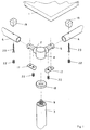
- a rectangular table top 1 is shown, the side edges of which Trusses 6 belong.
- connection node 2 is shown, the one Head 4 and two arms 5 includes.
- the trusses 6 are precision steel tubes formed, in which the arms 5 of the connecting node 2 conclusively can be introduced.
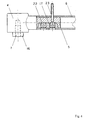
- the arms 5 have on their underside Recesses in which pressure pieces 17 are fitted. How closer in 4 these pressure pieces 17 are shown by means of the set screws 22 the inner wall of the cross member 6 tensioned, which means the hold between the Connection node 2 and the truss 6 is made.
- 1 and 4 in a bore for a threaded pin 22 on the top of the Traverse 6 also an additional hole for a chipboard screw 23, by means of which the traverse 6 via the spacer 19 on the table top 1 is screwed on.
- the head 4 of the connection node 2 has a bore 7, in which the pillar 3 by means of the threaded pin 9 can be screwed.
- the pedestal 3 is advantageously a Extruded aluminum profile into which the threaded pin 9 is screwed.
- the head 4 has a collar 16 over which a spacer 18 can be placed, which regulates the distance between head 4 and column 3.
- the tab 10 can also be used, preferably above its first hole 11, which is designed as an elongated hole.
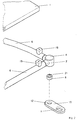
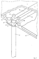
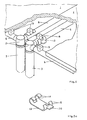
- the tab 10 with the two holes 11 and 12 is shown in Fig. 2. How said, it is with its slot 11 between the column 3 and head 4 one Connection node 2 screwed onto a table top 1 (Fig.1). In her another hole 12 can then the head 4 of the connecting node 2 one adjacent table top 1 can be hung (Fig.2). This is done using the Plastic plug 8.
- This is pot-shaped. It consists e.g. out Polypropylene. In its center, it has a conical and ribbed pin 21 on. With this pin 21 it is in the bore 7 (Fig.4) of the head 4th pressed. The inner part of the pot then comprises the collar 16 of the head 4.
- the outer part of the pot has a diameter slightly above that The diameter of the hole 12 of the tab 10 is such that a firm, stiff seat of the plug 8 in the hole 12 results.
- the plug 8 serves as a surface-protecting element when stacking the tabletops 1.
- connection node 2 of the adjacent table top 1 by means of (here not shown) plastic plug 8 hooked.
Landscapes
- Engineering & Computer Science (AREA)
- General Engineering & Computer Science (AREA)
- Mechanical Engineering (AREA)
- Furniture Connections (AREA)
- Treatment Of Fiber Materials (AREA)
- Accommodation For Nursing Or Treatment Tables (AREA)
- Standing Axle, Rod, Or Tube Structures Coupled By Welding, Adhesion, Or Deposition (AREA)
- Mobile Radio Communication Systems (AREA)
Claims (7)
- Système pour établir différentes configurations de table, dans lequel des tables peuvent être assemblées les unes aux autres en formant une surface de table continue, et qui comporte au moins les parties suivantes:caractérisé en ce quedeux tablettes de table (1) présentant au moins un bord latéral rectiligne,trois noeuds de liaison (2) connus en soi aux deux extrémités des bords latéraux, un noeud de liaison (2) étant constitué d'une tête (4) dotée de deux bras (5) qui s'étendent parallèlement à la tablette de table (1) dans une direction différente et qui sont configurés chacun pour la liaison à une traverse (6) qui peut être fixée en dessous de la tablette de table (1), et la tête (4) présentant un alésage fileté (7) perpendiculaire à la tablette de table (1), ettrois colonnes de pose (3) qui peuvent être vissées dans les alésages filetés (7) au moyen de tourillons filetés (9),au moins un organe d'assemblage (10; 13) est prévu pour l'assemblage des tablettes de table (1),l'organe d'assemblage étant constitué d'une patte (10) dotée de deux trous (11, 12) et qui peut être vissé par l'un de ces trous (11) sur la tête (4) du noeud de liaison (2) au moyen de la colonne de pose (3), la tête (4) d'un noeud de liaison (2) d'une tablette de table (1) voisine pouvant être fixée dans l'autre trou (12),ou étant constitué d'une pince élastique (13) en matière synthétique qui peut être placée à pivotement sur la traverse (6) d'un premier élément de table au moyen d'un premier dispositif d'accrochage (14) et qui peut être pincée sur la traverse (6) d'un deuxième élément de table, voisin du premier élément, au moyen d'un deuxième dispositif d'accrochage (15).
- Système selon la revendication 1, caractérisé en ce que:la tête (4) du noeud de liaison (2) présente sur le côté de l'alésage (7) un collet cylindrique (16) dont le diamètre correspond à celui du deuxième trou (12) de la patte (10),les traverses (6) qui peuvent être fixées sur les bras (5) du noeud de liaison (2) sont configurées en forme de tube,les bras (5) du noeud de liaison (2) peuvent être insérés en même temps qu'une pièce de compression (17) dans les traverses (6), et les pièces de compression (17) peuvent être serrées dans la traverse (6) au moyen de tiges filetées (18), etdes pièces d'écartement (19) sont prévues, par lesquelles les traverses (6) peuvent être fixées sur la tablette de table (1).
- Système selon les revendications 1 et 2, caractérisé en ce que les deux dispositifs d'accrochage (14, 15) de la pince (13) en matière synthétique sont chaque fois constitués de deux doigts qui chevauchent les traverses (6) sur les deux côtés d'une pièce d'écartement (19), la pince (13) en matière synthétique présentant une poignée (20) permettant son pivotement à la main.
- Système selon la revendication 1, caractérisé en ce que:un bouchon en plastique (8) est vissé dans l'alésage fileté (7) de la tête (4),ce bouchon en plastique (8) est configuré en forme de chapeau avec un tourillon central (21),le diamètre intérieur du chapeau est tel qu'il entoure le collet (16) prévu sur la tête (4) du noeud de liaison (2),le diamètre extérieur du chapeau est tel qu'il peut être enfoncé de manière serrée dans le trou (12) d'une patte (10), etle tourillon (21) est de configuration conique et moleté de telle sorte qu'il peut être fixé par enfoncement dans l'alésage (7) de la tête (4) du noeud de liaison (2).
- Système selon l'une des revendications précédentes, caractérisé en ce que toutes les tablettes de table (1) présentent la même- structure, mais présentent cependant des modules de différents formats et différentes formes géométriques.
- Système selon l'une des revendications précédentes, caractérisé en ce que les noeuds de liaison (2) sont des pièces coulées en aluminium et les colonnes de pose (3) sont des profilés extrudés en aluminium.
- Système selon la revendication 1, caractérisé en ce que la patte (10) peut être fixée sur le deuxième noeud de liaison (2) au moyen d'une vis moletée, par le trou (12) qui n'est pas vissé sur le premier noeud de liaison (2) par l'intermédiaire de la colonne de pose (3).
Applications Claiming Priority (2)
| Application Number | Priority Date | Filing Date | Title |
|---|---|---|---|
| DE19530780 | 1995-08-22 | ||
| DE19530780A DE19530780A1 (de) | 1995-08-22 | 1995-08-22 | System zum Erstellen variabler Tischkonfigurationen |
Publications (3)
| Publication Number | Publication Date |
|---|---|
| EP0761129A2 EP0761129A2 (fr) | 1997-03-12 |
| EP0761129A3 EP0761129A3 (fr) | 2001-01-17 |
| EP0761129B1 true EP0761129B1 (fr) | 2003-01-08 |
Family
ID=7770049
Family Applications (1)
| Application Number | Title | Priority Date | Filing Date |
|---|---|---|---|
| EP96112639A Expired - Lifetime EP0761129B1 (fr) | 1995-08-22 | 1996-08-05 | Système pour établir différentes configurations de tables |
Country Status (4)
| Country | Link |
|---|---|
| EP (1) | EP0761129B1 (fr) |
| AT (1) | ATE230575T1 (fr) |
| DE (2) | DE19530780A1 (fr) |
| ES (1) | ES2187596T3 (fr) |
Cited By (1)
| Publication number | Priority date | Publication date | Assignee | Title |
|---|---|---|---|---|
| EP4403070A1 (fr) * | 2023-01-18 | 2024-07-24 | Yotrio Group Co., Ltd. | Une table d'extérieur demontable |
Families Citing this family (7)
| Publication number | Priority date | Publication date | Assignee | Title |
|---|---|---|---|---|
| SE518360C2 (sv) * | 2000-05-09 | 2002-10-01 | Stefan Soederlund | Sammanfogningsanordning |
| ITBO20010307A1 (it) * | 2001-05-17 | 2002-11-17 | Work Corp Inc S R L | Struttura per la realizzazione di articoli di arredamento a configurazione variabile |
| FR2870443B1 (fr) * | 2004-05-21 | 2006-12-08 | Atal Sa | Mobiliers de bureau, et plus particulierement des mobiliers de bureau demontables |
| ES2311377B1 (es) * | 2006-10-25 | 2009-12-02 | Akaba, S.A. | Armazon-bastidor para mesas de configuracion variable. |
| GR1006721B (el) * | 2008-12-19 | 2010-03-09 | Αθανασιος Κωνσταντινου Παπαπαναγιωτου | Συνδεσμολογια μεταλλικων σωληνωτων στοιχειων με κομβο εσωτερικης συνδεσης |
| TWM486995U (zh) * | 2014-04-03 | 2014-10-01 | Timotion Technology Co Ltd | 易於展收的電動桌腳架 |
| DE102016206748A1 (de) * | 2016-04-21 | 2017-10-26 | Habermaass Gmbh | Möbelstück mit einem Eckverbinder |
Family Cites Families (7)
| Publication number | Priority date | Publication date | Assignee | Title |
|---|---|---|---|---|
| FR2135510B1 (fr) * | 1971-05-06 | 1973-05-11 | Garde Paul | |
| DE2155234A1 (de) * | 1971-11-06 | 1973-05-10 | Rolf Voelkle | Nach dem baukastenprinzip zusammensetzbares gestell |
| FR2402430A1 (fr) * | 1977-09-12 | 1979-04-06 | Alsace Sa Plastra Plastiques | Petit meuble du type table, presentant un ou plusieurs elements de support suspendus |
| GB8326429D0 (en) * | 1983-10-03 | 1983-11-02 | Chiu Ping | Joint structure |
| US5035186A (en) * | 1988-03-05 | 1991-07-30 | Roder Gmbh Sitzmobelwerke | Table having a connection device |
| DE9006147U1 (de) * | 1990-05-31 | 1991-09-26 | Gerd und Bernd Vieler KG, 5860 Iserlohn | Display-Gestell aus Rundprofil-Stangen und Eckverbindern zur Präsentation und zum Verkauf von Waren |
| DE9416016U1 (de) * | 1994-10-05 | 1995-01-05 | Ensslen GmbH, 72222 Ebhausen | Tisch |
-
1995
- 1995-08-22 DE DE19530780A patent/DE19530780A1/de not_active Withdrawn
-
1996
- 1996-08-05 DE DE59610038T patent/DE59610038D1/de not_active Expired - Fee Related
- 1996-08-05 AT AT96112639T patent/ATE230575T1/de not_active IP Right Cessation
- 1996-08-05 EP EP96112639A patent/EP0761129B1/fr not_active Expired - Lifetime
- 1996-08-05 ES ES96112639T patent/ES2187596T3/es not_active Expired - Lifetime
Cited By (1)
| Publication number | Priority date | Publication date | Assignee | Title |
|---|---|---|---|---|
| EP4403070A1 (fr) * | 2023-01-18 | 2024-07-24 | Yotrio Group Co., Ltd. | Une table d'extérieur demontable |
Also Published As
| Publication number | Publication date |
|---|---|
| EP0761129A2 (fr) | 1997-03-12 |
| EP0761129A3 (fr) | 2001-01-17 |
| DE19530780A1 (de) | 1997-02-27 |
| DE59610038D1 (de) | 2003-02-13 |
| ES2187596T3 (es) | 2003-06-16 |
| ATE230575T1 (de) | 2003-01-15 |
Similar Documents
| Publication | Publication Date | Title |
|---|---|---|
| DE3049957C2 (de) | Geraetegestell | |
| EP1854373A2 (fr) | Système de table | |
| DE3617297A1 (de) | Sitzmoebel, insbesondere stuhl | |
| DE3515034C2 (fr) | ||
| DE2934795C3 (de) | Anordnung zur lösbaren Verbindung von Bauteilen | |
| DE4336282A1 (de) | Verbindungselement für zwei sich kreuzende Rohre | |
| EP0761129A2 (fr) | Système pour établir différentes configurations de tables | |
| DE10019292A1 (de) | Modulares Tischsystem | |
| DE3920959C2 (fr) | ||
| DE10030919B4 (de) | Zerlegbarer Profilrohrrahmen sowie Tischsystem mit einem solchen Profilrohrrahmen | |
| DE3920285C2 (fr) | ||
| DE29521508U1 (de) | System zum Erstellen variabler Tischkonfigurationen | |
| DE2912815C2 (fr) | ||
| DE19526932C1 (de) | Tisch | |
| DE4114991C2 (fr) | ||
| DE4219852A1 (de) | Vorrichtung für ein schraubenlos zusammenfügbares Regalsystem | |
| DE3715932C1 (en) | Table combination | |
| DE4428390A1 (de) | Tischuntergestellsystem zur Aufnahme und zum Befestigen einer Tischplatte | |
| DE4235320A1 (de) | Verkettungssystem zum Verketten von Möbeln, insbesondere Bürotischen | |
| DE10051397A1 (de) | Zerlegbares Möbelstück | |
| DE102022126606A1 (de) | Transportables Klettergestell, insbesondere für Kleinkinder | |
| DE29717781U1 (de) | Säulentisch | |
| DE3734533A1 (de) | Knotenpunktsystem fuer messestandkonstruktionen und aehnliche aufbauten aus hohlprofilstaeben | |
| CH722127B1 (de) | Modulares, mehrfach montierbares und demontierbares Gestellsystem | |
| WO1992021832A1 (fr) | Dispositif d'assemblage articule demontable de panneaux prefabriques de cloison en forme de plaques |
Legal Events
| Date | Code | Title | Description |
|---|---|---|---|
| PUAI | Public reference made under article 153(3) epc to a published international application that has entered the european phase |
Free format text: ORIGINAL CODE: 0009012 |
|
| AK | Designated contracting states |
Kind code of ref document: A2 Designated state(s): AT CH DE ES FR GB IT LI NL |
|
| PUAL | Search report despatched |
Free format text: ORIGINAL CODE: 0009013 |
|
| AK | Designated contracting states |
Kind code of ref document: A3 Designated state(s): AT CH DE ES FR GB IT LI NL |
|
| RIC1 | Information provided on ipc code assigned before grant |
Free format text: 7A 47B 87/00 A, 7A 47B 13/02 B, 7F 16B 12/40 B, 7A 47B 13/06 B |
|
| 17P | Request for examination filed |
Effective date: 20010522 |
|
| 17Q | First examination report despatched |
Effective date: 20020213 |
|
| GRAG | Despatch of communication of intention to grant |
Free format text: ORIGINAL CODE: EPIDOS AGRA |
|
| GRAG | Despatch of communication of intention to grant |
Free format text: ORIGINAL CODE: EPIDOS AGRA |
|
| GRAG | Despatch of communication of intention to grant |
Free format text: ORIGINAL CODE: EPIDOS AGRA |
|
| GRAH | Despatch of communication of intention to grant a patent |
Free format text: ORIGINAL CODE: EPIDOS IGRA |
|
| GRAH | Despatch of communication of intention to grant a patent |
Free format text: ORIGINAL CODE: EPIDOS IGRA |
|
| GRAA | (expected) grant |
Free format text: ORIGINAL CODE: 0009210 |
|
| AK | Designated contracting states |
Kind code of ref document: B1 Designated state(s): AT CH DE ES FR GB IT LI NL |
|
| REF | Corresponds to: |
Ref document number: 230575 Country of ref document: AT Date of ref document: 20030115 Kind code of ref document: T |
|
| REG | Reference to a national code |
Ref country code: GB Ref legal event code: FG4D Free format text: NOT ENGLISH |
|
| REG | Reference to a national code |
Ref country code: CH Ref legal event code: EP |
|
| REF | Corresponds to: |
Ref document number: 59610038 Country of ref document: DE Date of ref document: 20030213 Kind code of ref document: P |
|
| GBT | Gb: translation of ep patent filed (gb section 77(6)(a)/1977) |
Effective date: 20030401 |
|
| ET | Fr: translation filed | ||
| REG | Reference to a national code |
Ref country code: ES Ref legal event code: FG2A Ref document number: 2187596 Country of ref document: ES Kind code of ref document: T3 |
|
| PGFP | Annual fee paid to national office [announced via postgrant information from national office to epo] |
Ref country code: NL Payment date: 20030728 Year of fee payment: 8 Ref country code: GB Payment date: 20030728 Year of fee payment: 8 Ref country code: CH Payment date: 20030728 Year of fee payment: 8 |
|
| PGFP | Annual fee paid to national office [announced via postgrant information from national office to epo] |
Ref country code: AT Payment date: 20030729 Year of fee payment: 8 |
|
| PGFP | Annual fee paid to national office [announced via postgrant information from national office to epo] |
Ref country code: DE Payment date: 20030805 Year of fee payment: 8 |
|
| PGFP | Annual fee paid to national office [announced via postgrant information from national office to epo] |
Ref country code: ES Payment date: 20030808 Year of fee payment: 8 |
|
| PGFP | Annual fee paid to national office [announced via postgrant information from national office to epo] |
Ref country code: FR Payment date: 20030813 Year of fee payment: 8 |
|
| PLBE | No opposition filed within time limit |
Free format text: ORIGINAL CODE: 0009261 |
|
| STAA | Information on the status of an ep patent application or granted ep patent |
Free format text: STATUS: NO OPPOSITION FILED WITHIN TIME LIMIT |
|
| 26N | No opposition filed |
Effective date: 20031009 |
|
| PG25 | Lapsed in a contracting state [announced via postgrant information from national office to epo] |
Ref country code: GB Free format text: LAPSE BECAUSE OF NON-PAYMENT OF DUE FEES Effective date: 20040805 Ref country code: AT Free format text: LAPSE BECAUSE OF NON-PAYMENT OF DUE FEES Effective date: 20040805 |
|
| PG25 | Lapsed in a contracting state [announced via postgrant information from national office to epo] |
Ref country code: ES Free format text: LAPSE BECAUSE OF NON-PAYMENT OF DUE FEES Effective date: 20040806 |
|
| PG25 | Lapsed in a contracting state [announced via postgrant information from national office to epo] |
Ref country code: LI Free format text: LAPSE BECAUSE OF NON-PAYMENT OF DUE FEES Effective date: 20040831 Ref country code: CH Free format text: LAPSE BECAUSE OF NON-PAYMENT OF DUE FEES Effective date: 20040831 |
|
| PG25 | Lapsed in a contracting state [announced via postgrant information from national office to epo] |
Ref country code: NL Free format text: LAPSE BECAUSE OF NON-PAYMENT OF DUE FEES Effective date: 20050301 Ref country code: DE Free format text: LAPSE BECAUSE OF NON-PAYMENT OF DUE FEES Effective date: 20050301 |
|
| GBPC | Gb: european patent ceased through non-payment of renewal fee |
Effective date: 20040805 |
|
| REG | Reference to a national code |
Ref country code: CH Ref legal event code: PL |
|
| PG25 | Lapsed in a contracting state [announced via postgrant information from national office to epo] |
Ref country code: FR Free format text: LAPSE BECAUSE OF NON-PAYMENT OF DUE FEES Effective date: 20050429 |
|
| NLV4 | Nl: lapsed or anulled due to non-payment of the annual fee |
Effective date: 20050301 |
|
| REG | Reference to a national code |
Ref country code: FR Ref legal event code: ST |
|
| PG25 | Lapsed in a contracting state [announced via postgrant information from national office to epo] |
Ref country code: IT Free format text: LAPSE BECAUSE OF NON-PAYMENT OF DUE FEES;WARNING: LAPSES OF ITALIAN PATENTS WITH EFFECTIVE DATE BEFORE 2007 MAY HAVE OCCURRED AT ANY TIME BEFORE 2007. THE CORRECT EFFECTIVE DATE MAY BE DIFFERENT FROM THE ONE RECORDED. Effective date: 20050805 |
|
| REG | Reference to a national code |
Ref country code: ES Ref legal event code: FD2A Effective date: 20040806 |