EP0761186A2 - Charnière orthopédique à deux pivots réels avec commande de mouvement incrémentiel - Google Patents
Charnière orthopédique à deux pivots réels avec commande de mouvement incrémentiel Download PDFInfo
- Publication number
- EP0761186A2 EP0761186A2 EP96306312A EP96306312A EP0761186A2 EP 0761186 A2 EP0761186 A2 EP 0761186A2 EP 96306312 A EP96306312 A EP 96306312A EP 96306312 A EP96306312 A EP 96306312A EP 0761186 A2 EP0761186 A2 EP 0761186A2
- Authority
- EP
- European Patent Office
- Prior art keywords
- stop
- hinge
- flexion
- extension
- insert
- Prior art date
- Legal status (The legal status is an assumption and is not a legal conclusion. Google has not performed a legal analysis and makes no representation as to the accuracy of the status listed.)
- Withdrawn
Links
Images


Classifications
-
- A—HUMAN NECESSITIES
- A61—MEDICAL OR VETERINARY SCIENCE; HYGIENE
- A61F—FILTERS IMPLANTABLE INTO BLOOD VESSELS; PROSTHESES; DEVICES PROVIDING PATENCY TO, OR PREVENTING COLLAPSING OF, TUBULAR STRUCTURES OF THE BODY, e.g. STENTS; ORTHOPAEDIC, NURSING OR CONTRACEPTIVE DEVICES; FOMENTATION; TREATMENT OR PROTECTION OF EYES OR EARS; BANDAGES, DRESSINGS OR ABSORBENT PADS; FIRST-AID KITS
- A61F5/00—Orthopaedic methods or devices for non-surgical treatment of bones or joints; Nursing devices ; Anti-rape devices
- A61F5/01—Orthopaedic devices, e.g. long-term immobilising or pressure directing devices for treating broken or deformed bones such as splints, casts or braces
- A61F5/0102—Orthopaedic devices, e.g. long-term immobilising or pressure directing devices for treating broken or deformed bones such as splints, casts or braces specially adapted for correcting deformities of the limbs or for supporting them; Ortheses, e.g. with articulations
- A61F5/0123—Orthopaedic devices, e.g. long-term immobilising or pressure directing devices for treating broken or deformed bones such as splints, casts or braces specially adapted for correcting deformities of the limbs or for supporting them; Ortheses, e.g. with articulations for the knees
-
- A—HUMAN NECESSITIES
- A61—MEDICAL OR VETERINARY SCIENCE; HYGIENE
- A61F—FILTERS IMPLANTABLE INTO BLOOD VESSELS; PROSTHESES; DEVICES PROVIDING PATENCY TO, OR PREVENTING COLLAPSING OF, TUBULAR STRUCTURES OF THE BODY, e.g. STENTS; ORTHOPAEDIC, NURSING OR CONTRACEPTIVE DEVICES; FOMENTATION; TREATMENT OR PROTECTION OF EYES OR EARS; BANDAGES, DRESSINGS OR ABSORBENT PADS; FIRST-AID KITS
- A61F5/00—Orthopaedic methods or devices for non-surgical treatment of bones or joints; Nursing devices ; Anti-rape devices
- A61F5/01—Orthopaedic devices, e.g. long-term immobilising or pressure directing devices for treating broken or deformed bones such as splints, casts or braces
- A61F5/0102—Orthopaedic devices, e.g. long-term immobilising or pressure directing devices for treating broken or deformed bones such as splints, casts or braces specially adapted for correcting deformities of the limbs or for supporting them; Ortheses, e.g. with articulations
- A61F2005/0132—Additional features of the articulation
- A61F2005/0165—Additional features of the articulation with limits of movement
- A61F2005/0167—Additional features of the articulation with limits of movement adjustable
Definitions
- This invention relates to hinges employed in orthoses and orthopaedic braces used on the human body particularly the knee joint.
- the invention relates to novel for limiting the flexion and extension travel of the arms of a true bi-pivotal hinge.
- first widely used type there are two hinge arms joined at and flexing about a single pivot.
- This type is generally referred to by those skilled in the art as the uni-pivotal or monocentric type.
- a second type there are two hinge arms each having its own pivot and also each having a set gear teeth about the periphery of the part which extends between the pivots.
- the arms are so sized and arranged that the gear teeth mesh between the pivot points thereby integrating the arm movements.
- This type is generally referred to by those skilled in the art as the geared bi-axial, geared duo-centric or geared polycentric type. The latter term is perhaps the most widely recognised.
- hinge types are remotely physiological in the way they move and because their mechanical action is so unlike that of the human knee their use in a brace construct may be positively deleterious to an injured, repaired or deformed knee.
- brace construct is used by those skilled in the art to describe the resultant mechanical arrangement of a brace and the leg to which it is attached.
- a combination of casting materials (such as Plaster of Paris or resin impregnated bandages) and cast bracing hinges as well as braces secured on the leg by means such as straps are brace constructs once they are in place on the leg.
- the knee is a modified. crossed, four bar linkage comprising the rigid elements femur, tibia and the anterior and the posterior cruciate ligaments. Its axis of rotation moves or posteriorly as the knee is flexed from the fully extended position.
- the locus or track of the axis of knee rotation is called the instant Centre Pathway" which exactly defines the moving path of the centre of knee rotation at any given instant.
- Uni-axial and geared polycentric hinges do not have this construction; they do not move in this manner and within a brace construct they cannot accommodate or track the complex motion of the knee properly.
- hinge design used in orthopaedic splints and braces employed at the knee has two hinge arm each having its own pivot but in this design there are no gear teeth. Thus in this type, the arm movements are not integrated and each arm can always move independently without affecting the other.
- This type of hinge is generally referred to by those skilled in the art as the true bi-axial, true bi-pivotal or simply just bi-pivotal type. It continues to grow in popularity with the realisation that such a construction is superior to the others in providing the freedom necessary to accommodate the complex and changing locus of the axis of the knee throughout the entire flexion/extension cycle.
- Both bi-pivotal hinges and geared polycentric hinges are, in mechanical terms, three bar linkages.
- the geared integration of the hinge arms in the geared polycentric type arms causes the loss of one degree of freedom.
- both types require at least one stop at or near the fully extended position to prevent over-travel of the knee into hyperextension.
- a three bar linkage hinge mechanism offers the most practical and appropriate mechanical arrangement for accommodating the complex motion of the knee.
- braces which have incremental extension and flexion stop are secured separately by at least one screw for each stop and there is often a hinge cover which has to be removed as well.
- continuously variable stop mechanisms are now mainly found in rehabilitation braces which are used immediately following injury or repair to knee ligaments and are otherwise generally simpler braces. In those patients at a later stage of rehabilitation and returning to active sport, discontinuous or incremental stop mechanisms are acceptable in the functional knee braces typically prescribed at that stage.
- the present invention provides a true bi-pivotal hinge, for orthopaedic and orthotic braces used on the human body and particularly the knee, which has an improved incremental motion limiting mechanism.
- a true bi-pivotal hinge is provided with a series of novel, more or less diamond shaped, interchangeable, metal, combined extension and flexion insert stops.
- Each insert stop body provides at least one and optionally two different angular settings for extension limitation and at least one and optionally, two different angular settings for flexion limitation.
- this novel arrangement it is not necessary to have any part of the insert stop accommodated and disposed between the extreme ends of the hinge arms between the pivots.
- the arrangement of the invention allows the instant hinge to have narrow pivot spacing in the range 24mm to 30mm which is the optimal arrangement for a true bi-pivotal hinge.
- Such an unconstrained bi-pivotal hinge which is a three bar linkage, offers excellent practical accommodation, during flexion and extension motion, of the complex motion of the knee's four bar linkage mechanism. This is accomplished without the introduction of extraneous forces associated with the use of uni-axial and geared polycentric hinges.
- each diamond shaped insert stop is secured by a single screw which passes through either the front plate or back plate of the hinge.
- a true bi-pivotal hinge, with narrow pivot spacing, for use in orthopaedic and orthotic braces which has a series of single, flat, interchangeable, incremental insert stops made in suitable metals such as titanium or stainless steel and which are secured in the flexion angle of the hinge.
- the incremental metal insert stops having a first pair of angled extension stop faces, one for each independently pivoted hinge arm, each face being disposed at half the total extension stop angle required.
- the incremental metal insert stops have a second pair of angled extension stop faces, one for each independently pivoted hinge arm, each face being disposed at half a total extension stop angle required and optionally differing from the first extension stop angle by a clinically useful increment.
- the incremental metal insert stops have a first pair of angled flexion stop faces, one of each independently pivoted hinge arm, each face being disposed at half the total flexion stop angle required.
- the incremental metal insert stops have a second pair of angled flexion stop faces, one for each independently pivoted hinge arm, each face being disposed at half a total flexion stop angle required and optionally differing from the first extension stop angle by a clinically useful increment.
- each interchangeable metal insert stop body is secured by a single screw which passes non-threadedly through either a front plate or back plate of the hinge body and which is received threadedly into the stop body.
- each approximately diamond shaped insert stop having a pair of angled extension stop faces not selected may be used as a handle or grip for introducing the selected pair of angled extension stop faces into the hinge body at the time of fitting or removal.
- each insert stop body is provided with markings which clearly indicate the total angular values of each pair of flexion and extension stops.
- the principal object of this invention to provide a true bi-pivotal hinge for use in orthopaedic and orthotic braces having narrow pivot spacings, preferably disposed apart by a distance measurement between centres in the range 24mm to 30mm and provided with a series of interchangeable, flat, metal, or more or less diamond shaped insert stops each offering a plurality of paired extension stops and a plurality of paired flexion stops for limiting extension and flexion travel of both the hinge arms.
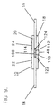
- Fig. 1 is a lateral front view of part of an orthopaedic knee brace with a fully assembled true bi-pivotal hinge according to the present invention.
- Fig. 2 is a lateral front view of part of an orthopaedic knee brace fitted with a true bi-pivotal hinge with the hinge cover and front plate partly cut away to show part of a first combined extension and flexion insert stop according to the present invention. The hinge arms are shown extended against the stop.
- Fig. 3 is a lateral front view of the instant hinge with the hinge cover and front plate removed to show a second view of a first combined extension and flexion insert stop with the hinge arms flexed against the stop.
- Fig. 4 is a lateral front view analogous to Fig. 3 showing a first view of a second combined extension and flexion insert stop according to the present invention. The hinge arms are shown extended against the insert stop.
- Fig. 5 is a lateral front view analogous to Fig. 2 but with slightly different parts of the hinge cover and front plate cut away and showing a second view of part of a second combined extension and flexion insert stop according to the present invention.
- the hinge arms are shown flexed against the insert stop.
- Figs. 6, 7 and 8 are front or lateral views of further combined extension and flexion insert stop configurations according to the present invention.
- Fig. 9 is a posterior view of a hinge according to the present invention with a combined extension and flexion insert stop in place.
- a true bi-pivotal hinge has the general designation 10 and is generally represented as part of an orthopaedic knee brace 12. It is to be understood that hinge 10 will generally but not always, be used in a paired configuration with one such structure being disposed medially and the other laterally with respect to the human knee. Hinge 10 comprises the major structural elements first and second substantially flat hinge arms 14 and 16, a substantially flat front plate 18 and a substantially flat front plate 18 and a substantially flat back plate 20. These elements are conveniently made in metals such as aluminium or titanium. As described, hinge 10 is not a handed structure.
- Front plate 18 and back plate 20 are disposed in a parallel relationship and hinge arms 14 and 16 are disposed between them, each being independently pivotally mounted upon pivot rivet axis means 22 and 24 (shown in section in Figs 2-5) provided with bushing means 26 and 28 (28 is shown in section in Figs 2-5; 26 is shown in section Figs 3 and 4).
- the spacing between the centres of 22 and 24 is strongly preferred to be in the range 24mm-30mm.
- hinge arms 14 and 16 are overmoulded in a suitable soft but durable material such as an injection moulding grade of synthetic rubber indicated at 30 and 32.
- hinge 10 has a front cover 34, conveniently made in moulded plastics.
- the first purpose of overmoulds 30 and 32 and hinge cover 34 is to ensure that metal parts do not impinge upon the person of the wearer and also if the device where to be used in contact sports to protect another participant.
- a second purpose is to enhance the cosmetic appearance.
- Hinge cover 34 has a further purpose which will be described, in context, below.
- hinge arms 14 and 16 has an extension 36 and 38 which extends beyond and between pivot rivets 22 and 24, respectively but which neither interdigitates with nor touches the other.
- Posterior edges 40 and 42 of extensions 36 and 38 and the non-overmoulded posterior edges 44 and 45 of hinge arms 14 and 16 which lie disposed between front plate 18 and back plate 20, constitute abutment faces.
- Abutment faces 40 and 44 lie in the same plane and when hinge arm 14 is in full extension these faces are also parallel to a line c-c 1 joining the centres of pivot rivets axis means 22 and 24.
- faces 42 and 46 are also in the same plane and are additionally co-planar with 40 and 44.
- faces 42 and 46 are also parallel to centre line c-c 1 between pivot rivet axis means 22 and 24.
- Abutment faces 40, 42,44 and 45 co-operate with corresponding structures, described below, provided by each and every one of a series of approximately diamond shaped combined extension and flexion insert stops.
- Five insert stops in such a series are illustrated and are designated 100, 200, 300, 400 and 500. However, it is to be understood that whilst some of these insert stops are typical of those which may commonly be used, they represent only a few of the possible combinations which may be made or required in rational clinical range from full extension or 0° to about 130° flexion.
- Combined extension and flexion insert stop 100 has a structure which is typical of the series. It is planar and made of suitable metals, such as titanium or stainless steel and has a thickness substantially the same as hinge arms 14 and 16. Insert stop 100 has a stop body 102 provided with a threaded hole 104. Threaded hole 104 provides means by which insert stop 100 is secured, threadedly, by screw 48 (shown in section in Figs. 3-5) to and against front plate 18 and hinge cover 34. Front plate 18 has a hole 50 (seen only in Fig. 5) for receival, non-threadedly, of screw 48 with minimal clearance.
- Hinge cover 34 has a tapered recess 52, centrally positioned in which is a hole (not seen) also for receival, non-threadedly, of screw 48.
- screw 48 When screw 48 is driven fully home, its head 54, lies just under flush with the surface 56 of hinge cover 34.
- the centre of hole 50 in front plate 18 is located on a line n-n 1 normal to and running posteriorly from centre line c-c 1 .
- This line also bisects the distance between the centres of pivots 22 and 24.
- the position of hole 50 is selected to optimise the geometrical solutions applied to the selection of insert stops.
- insert stops are symmetrical about an axis a-a 1 which runs from the apex of the first total extension stop angle to the apex of the second total stop angle. Insert stops are not necessarily symmetrical about an axial line b-b 1 drawn between the apices of angles between adjacent flexion stop faces. However, the position of the centre of the threaded securing hole illustrated at 104, 204, 304, 404 and 504 in the drawings always lies at the intersection of lines a-a 1 and b-b 1 .
- Insert stop geometry will be strongly influenced by the required stop angles selection but other factors, such as the width of hinge arms 14 and 16, the shape and position of extensions 36 and 28 and the overall shape and size of hinge body 10 and its other major components are important.
- each member 106, 108 of a first pair of extension stop faces is symmetrically disposed either side of a vertical apical axis at an angle of 5° to and above a horizontal axis, thus presenting, as illustrated in Fig. 2, a total extension stop angle of 10° to abutment faces 40 and 42 of extensions 36 and 18 of hinge arms 14 and 16, respectively.
- Each member 110, 112 of a second pair of extension stop faces is also symmetrically disposed either side of the vertical apical axis at an angle of 10° to and below the horizontal axis, thus providing, when required a second total extension stop angle of 20° for abutment faces 40 and 42.
- part 114 of stop body 102 which is adjacent to stop faces 110, 112 also functions as a tab or handle.
- This feature is useful when changing entire insert stops or switching stop values.
- screw 48 is removed and stop 100 is readily withdrawn using handle 114.
- Insert stop 100 is then reversed and handle 116, which is the equivalent part of stop body 102 adjacent to stop faces 106, 108 (seen in Figs. 2 and 3) is used to introduce extension stop faces 110, 112 into the correct position within hinge 10.
- Handle 116 may also be used to bold insert stop 100 in position while screw 48 is relocated and driven home. Provided hinge arm 14 and 16 are extended and flexed against insert stop 100 before screw 48 is fully tightened, stop 100 will centre itself and line up properly without the need for secondary adjustment of its position.
- each member 118, 120 of a first pair of flexion stop faces is symmetrically disposed either side of the vertical axis at an angle of 65° to and above the horizontal axis.
- This arrangement presents, as illustrated in Fig. 3, a total flexion stop angle of 130° to abutment faces 44 and 46.
- Each member 122, 124 of a second pair of flexion stop faces is also symmetrically disposed either side of the vertical apical axis at an angle of 65° to and below the horizontal axis thus also providing a total flexion stop angle of 130° for abutment faces 44 and 46.
- Radii 126, 128, 130 and 132 all have the same dimension, which is somewhat greater than the radius of curved portions 58 and 60 of hinge arms 14 and 16. This arrangement is to ensure clearance between insert stop 100 and hinge arms 14 and 16 at all positions of hinge arm travel between selected extension stop faces and selected stop faces. These radii are all tangential to a circle centred upon the intersection of axes a-a 1 and b-b 1 . This confers the basic diamond shape upon the central body portion of all insert stops. The radii add concavity to the sides and the stop selection superimposed upon this basic architecture dictates the final shape which varies considerably within the overall basic diamond pattern.
- single combined extension and flexion insert stop 100 located in the next flexion angle of hinge 10 offers extension blocking at 10° and 20° each with, effectively full flexion.
- This is a rational and desirable set of combinations for a knee in the later stages of rehabilitation following surgical repair to a ruptured anterior cruciate ligament (ACL).
- a healthy knee, without a brace fitted, may well flex beyond 130° but with a brace in place, above and below knee structures thereof will generally impinge upon one another at large flexion angles.
- insert stops according to the present invention may readily be made with any required flexion angle value.
- Combined extension and flexion insert stop 200 is analogous to insert stop 100 and has the equivalent structures 202-232. It differs only in that extension stop faces 206, 208 are symmetrically disposed either side of the vertical apical axis at an angle 15° to and above the horizontal axis and presents, as illustrated in Fig. 4 and 5, a total extension stop angle of 30° to abutment faces 40 and 42. Also extension stop faces 210, 212 are symmetrically disposed either side of the vertical apical axis at an angle of 20° to and below the horizontal axis providing, when required, a second total extension stop angle of 40° for abutment faces 40 and 42. Both flexion stop angles are 130°, as an insert stop 100.
- Combined extension and flexion insert stops 300, 400 and 500 shown isolated in Figs. 6-8, are also analogous to insert stop 100 and have the equivalent structures 302-332, 402-432 and 502-532. These insert stops are included to allow a discussion of the rationale for stop selection and of apparent limits of the diamond pattern architecture related to materials selection.
- insert stop 300 has first and second pairs of extension stop faces 304, 304; 308,310. Both pairs provide an extension stop angle of 0°, which is full extension. Insert stop 300 also has first and second pairs of flexion stop faces 318, 320; 322,324 both of which offer a flexion stop angle of 45° for abutment faces 44 and 46.
- Insert stop 300 is not truly rational under the present, an important advantage of which is to provide multiple combinations of extensions and when required, flexion as well, it is included because it represents a worse case scenario for the instant insert stops when under load.
- insert stop 300 has narrow left and right extremities in the region of flexion stop faces 318,320 and 322,324, respectively.
- a 45° flexion stop setting is most unlikely selection in a modern functional bracing based treatment regime for late rehabilitation following ACL or other ligamentous reconstruction and is outside the present author's experience.
- braces used earlier in the post-operative phase are usually preferred with continuous control of flexion and extension.
- insert stops are recommended to be made in the preferred metals. With such metals used in thicknesses likely to be preferred for hinge arm construction, tests have shown that insert stops configured as in 300 are adequate to withstand forces likely to be encountered during use.
- insert stop 400 represents a more rational but still rather unusual combination in which the first pair of extension stop faces 406,408 present a total extension stop angle of 10° and the second pair of extension stop faces 410,412 present a total extension stop angle of 20°. Both pairs of flexion stop faces 418,420; 422,424 present a total flexion stop angle of 60°.
- This insert stop is mainly included to indicate, by comparison with Fig. 6, that the amount of stop material available to support compression loads in flexion increases rapidly with increasing flexion stop angle.
- Insert stop 400 in Fig. 7 is shown with suitable preferred markings. The convention of marking each portion of a stop with the setting it actually has rather than those of the opposite end, is preferred as less confusing.
- insert stop 500 represents a rational combination in which the first pair of extension stop faces 506,508 present a total extension stop angle of 10° and the second pair of extension stop faces 510,512 present a total extension stop angle of 20°. Both pairs of flexion stop faces 518,520;522,524 present a total flexion stop angle of 90°.
- This insert stop is also included partly to indicate further by comparison with Figs. 6 and 7, that the amount of stop material available to support compression loads in flexion increases rapidly with increasing flexion stop angle.
- Fig. 8 shows both pairs of extension stop face angles and one pair of flexion stop face angles of stop 500 labelled.
- combination stops have two extension blocking angles and one flexion blocking angle. This reflects the fact that in practice during later stages of rehabilitation of the knee, there is a greater and more frequent requirement to revise extension blocking rather flexion blocking. Those charged with the care of patients, therefore, will often prefer to have to make less decisions about flexion (Which they will in any case often choose to set at full flexion) and have several combinations of extension stop immediately available which involve minimal stop changes.
- An advantage of the present invention is that in scenario, which is very likely, a carer would need only two insert stops for each hinge.
- Each insert stop would have both sets of flexion stops providing 130° of flexion block.
- One insert stop would offer extension blocking at 10° and 20° - as illustrated with respect to stop 100 in Figs. 2 and 3.
- the other insert stop would offer extension blocking at 30° and 40°.
- an orthopaedic brace according to the present invention and provided with such as set of insert stops would allow adjustment to:- Full extension with 90° or 130° of flexion 10° extension block with 60° or 130° of flexion 20°extension block with 90° or 130'°of flexion 30° extension block with 130° of flexion 40° extension block with 130° of flexion This range. providing 8 combinations from 4 insert stop entities, would cover most if not all requirements from early middle to late rehabilitation in a functional knee brace, even where a surgeon favours a 'straight-through' approach. This involves using afunctional knee brace throughout treatment, eschewing the use of a traditional co-called rehabilitation brace during the post-operative period and thereby reducing costs.
- hinge cover 34 is secured from behind the hinge 10 by a self-tapping screw 62 (shown in section Figs. 2 and 5).
- Self tapping screw 62 passes non-threadedly through a clearance hole 64 in back plate 20 and engages self-threadingly with a blind pilot hole 66 in a boss 68 (both shown in hidden detail in Fig. 1.
- This feature makes it necessary to remove or in any other way handle hinge cover 34 during an incremental insert stop change.
- since only a single screw 48, secures the combination extension and flexion insert stops of the present invention, the maximum number of parts which need to be handled is much less than in prior art system.
- any such insert stop is likely to have a 30° flexion stop as its selected functional partner. No patient wearing a functional or other orthopaedic knee brace so configured, would or could participate in contact sports.
- insert stops according to the present invention with full extension provided by both first and second pairs of extension stop faces, are likely be used by those who participate in contact sports.
- these insert stops will protrude only about 3mm into the posterior, flexion angle of the hinge which is an insignificant hazard.
- Fig. 1 which is at enlarged scale, will indicate how little insert stop 100 protrudes, even with the 10° extension block engaged and the 20° extension block functioning as a handle.
Landscapes
- Health & Medical Sciences (AREA)
- Nursing (AREA)
- Orthopedic Medicine & Surgery (AREA)
- Engineering & Computer Science (AREA)
- Biomedical Technology (AREA)
- Heart & Thoracic Surgery (AREA)
- Vascular Medicine (AREA)
- Life Sciences & Earth Sciences (AREA)
- Animal Behavior & Ethology (AREA)
- General Health & Medical Sciences (AREA)
- Public Health (AREA)
- Veterinary Medicine (AREA)
- Orthopedics, Nursing, And Contraception (AREA)
- Prostheses (AREA)
Applications Claiming Priority (2)
| Application Number | Priority Date | Filing Date | Title |
|---|---|---|---|
| US521547 | 1995-08-30 | ||
| US08/521,547 US5662596A (en) | 1995-08-30 | 1995-08-30 | True bi-pivotal orthopedic and orthotic hinge with incremental motion control |
Publications (2)
| Publication Number | Publication Date |
|---|---|
| EP0761186A2 true EP0761186A2 (fr) | 1997-03-12 |
| EP0761186A3 EP0761186A3 (fr) | 1999-04-14 |
Family
ID=24077166
Family Applications (1)
| Application Number | Title | Priority Date | Filing Date |
|---|---|---|---|
| EP96306312A Withdrawn EP0761186A3 (fr) | 1995-08-30 | 1996-08-30 | Charnière orthopédique à deux pivots réels avec commande de mouvement incrémentiel |
Country Status (2)
| Country | Link |
|---|---|
| US (1) | US5662596A (fr) |
| EP (1) | EP0761186A3 (fr) |
Cited By (3)
| Publication number | Priority date | Publication date | Assignee | Title |
|---|---|---|---|---|
| WO2004024040A3 (fr) * | 2002-09-11 | 2004-05-21 | Dj Orthopedics Dev Corp | Charniere verrouillable |
| WO2004078078A1 (fr) * | 2003-03-06 | 2004-09-16 | Fgp Srl | Joint articule pour une attelle de genou avec une extension angulaire reglable |
| EP2526906A1 (fr) * | 2011-05-27 | 2012-11-28 | F.G.P. Srl | Joint pour attelle orthopédique avec deux montants de plage angulaire réglable |
Families Citing this family (36)
| Publication number | Priority date | Publication date | Assignee | Title |
|---|---|---|---|---|
| CA2239144A1 (fr) * | 1998-06-08 | 1999-12-08 | Mission Sante Bois-Francs Inc. | Exerciseur orthopedique |
| US6732410B1 (en) | 1999-06-14 | 2004-05-11 | The United States Of America As Represented By The Secretary Of The Navy | Precision hinge mounting stops |
| USD448484S1 (en) | 2000-11-30 | 2001-09-25 | Scott Orthotic Labs, Inc. | Ankle joint for an ankle foot orthosis |
| US20020151930A1 (en) * | 2001-04-16 | 2002-10-17 | Jeremy Mills | Acupressure and reflexology clamp |
| US6969363B2 (en) * | 2002-02-15 | 2005-11-29 | Thuasne | Bicentric hinge for use in a brace |
| US7488300B2 (en) | 2002-02-15 | 2009-02-10 | Thusane | Bicentric hinge for use in a brace |
| US6859980B2 (en) * | 2002-06-06 | 2005-03-01 | Austin R. Baer | Covered pinned hinge |
| US20040068215A1 (en) * | 2002-10-08 | 2004-04-08 | Jeremy Adelson | Osteoarthritis knee brace apparatus and method |
| US7150721B2 (en) * | 2003-06-30 | 2006-12-19 | Thuasne | Knee brace with dynamic counterforce |
| US7500957B2 (en) * | 2004-02-05 | 2009-03-10 | Medical Technology, Inc. | Muscle powered dynamic knee brace |
| US20050273025A1 (en) * | 2004-05-19 | 2005-12-08 | Houser Guy M | Braces having an assembly for exerting a manually adjustable force on a limb of a user |
| US7811242B2 (en) | 2004-06-24 | 2010-10-12 | Djo, Llc | Motion controlling hinge for orthopedic brace |
| EP1791502A1 (fr) | 2004-09-09 | 2007-06-06 | Fastform Research Limited | Dispositif d'attelle et/ou de protection a ouverture geometrique renfermant une matiere thermoplastique remoulable |
| US7544174B2 (en) * | 2006-09-29 | 2009-06-09 | Djo, Llc | Quiet flexion/extension stop for orthopedic brace and orthopedic brace incorporating a quiet flexion/extension stop |
| US8512267B2 (en) * | 2010-03-08 | 2013-08-20 | Top Shelf Manufacturing, Llc | Over-molded flexible knee brace |
| WO2012037275A1 (fr) | 2010-09-16 | 2012-03-22 | Steadman Philippon Research Institute | Support pour le ligament croisé postérieur |
| US9021614B2 (en) | 2011-02-18 | 2015-05-05 | Medical Techology, Inc. | Leg protector for sports activities |
| US9615955B2 (en) | 2011-04-21 | 2017-04-11 | Breg, Inc. | Orthopedic knee brace with dynamically changing medial and lateral hinges |
| EP2773301B1 (fr) | 2011-10-31 | 2016-03-16 | Ossur Hf | Dispositif orthopédique pour le traitement dynamique du genou |
| USD716000S1 (en) | 2012-08-14 | 2014-10-21 | Medical Technology Inc. | Sports leg protector |
| US9539135B2 (en) | 2013-01-25 | 2017-01-10 | Ossur Hf | Orthopedic device having a dynamic control system and method for using the same |
| US10413437B2 (en) | 2013-01-25 | 2019-09-17 | Ossur Iceland Ehf | Orthopedic device having a dynamic control system and method for using the same |
| WO2014117109A1 (fr) | 2013-01-25 | 2014-07-31 | Ossur Hf | Dispositif orthopédique doté d'un système de commande dynamique |
| WO2014205103A1 (fr) | 2013-06-21 | 2014-12-24 | Ossur Hf | Système de tension dynamique pour dispositif orthopédique |
| EP3036068B1 (fr) | 2013-08-22 | 2018-09-19 | Ossur Iceland EHF | Outil limiteur de couple et procédé d'utilisation de celui-ci |
| US10512305B2 (en) | 2014-07-11 | 2019-12-24 | Ossur Hf | Tightening system with a tension control mechanism |
| US10653546B2 (en) | 2014-10-31 | 2020-05-19 | Ossur Hf | Orthopedic device having a dynamic control system |
| WO2016081688A1 (fr) | 2014-11-20 | 2016-05-26 | Ossur Iceland Ehf | Articulation polycentrique polymère |
| WO2016092051A1 (fr) | 2014-12-12 | 2016-06-16 | Fastform Research Ltd. | Dispositif d'orthèse multifonctionnel et procédé d'utilisation |
| USD787076S1 (en) * | 2015-04-17 | 2017-05-16 | Vision Quest Industries Incorporated | Orthotic device |
| DE102015217205A1 (de) * | 2015-09-09 | 2017-03-09 | Bauerfeind Ag | Schwenklimitierbares biaxiales Gelenk |
| US10370206B2 (en) * | 2016-03-07 | 2019-08-06 | Winston Products Llc | Loading ramp |
| WO2018106759A1 (fr) | 2016-12-06 | 2018-06-14 | Ossur Iceland Ehf | Articulation mobile destinée à être utilisée dans un système prothétique ou orthopédique |
| WO2019104302A2 (fr) | 2017-11-27 | 2019-05-31 | Ossur Iceland Ehf | Dispositif orthopédique ayant un élément de suspension |
| US12178729B2 (en) | 2019-03-26 | 2024-12-31 | Ossur Iceland Ehf | Hinge assembly for an orthopedic device |
| US20210169675A1 (en) | 2019-12-05 | 2021-06-10 | Vision Quest Industries Incorporated Dba Vq Orthocare | Orthopedic device |
Family Cites Families (16)
| Publication number | Priority date | Publication date | Assignee | Title |
|---|---|---|---|---|
| US4239524A (en) * | 1979-03-05 | 1980-12-16 | Schering Aktiengesellschaft | Thiadiazolyl ureas with herbicidal effect |
| US4520802A (en) * | 1983-09-30 | 1985-06-04 | Mercer James D | Bi-axial orthotic device |
| US4697583A (en) * | 1985-01-29 | 1987-10-06 | Don Joy Orthopedic, Inc. | Four-point anterior cruciate ligament brace |
| GB2182714B (en) * | 1985-04-18 | 1989-06-28 | David Ernest Young | An orthopaedic hinge mechanism |
| US4715363A (en) * | 1986-09-26 | 1987-12-29 | Detty Garnett E | Knee brace with extension angle establishing means |
| US4732143A (en) * | 1987-02-13 | 1988-03-22 | Spectrum Orthopedics, Ltd. | Selectable extension stop for a polycentric hinge |
| GB2208065B (en) * | 1987-02-18 | 1991-10-09 | David Ernest Young | Bi-pivotal orthopaedic and orthotic hinge with improved adjustment means |
| US4777941A (en) * | 1987-07-29 | 1988-10-18 | Borig Donald A | Orthopedic knee prosthesis and hinge |
| US4881532A (en) * | 1987-07-30 | 1989-11-21 | Borig Donald A | Orthopedic hip hinge providing adjustment for abduction |
| GB2215394A (en) * | 1988-02-02 | 1989-09-20 | Protectair Ltd | Adjustable bipivotal hinge |
| GB8802288D0 (en) * | 1988-02-02 | 1988-03-02 | Protectair Ltd | Improved adjustment means for bi-pivotal orthopaedic & orthotichings |
| GB2227520B (en) * | 1988-10-26 | 1992-08-12 | Protectair Ltd | Adjustable hinge device |
| US4940044A (en) * | 1989-02-08 | 1990-07-10 | Innovation Sports, Inc. | Knee brace incorporating adjustment means to accommodate anatomical variations of the knee joint and leg |
| EP0413424A1 (fr) * | 1989-08-14 | 1991-02-20 | Protectair Limited | Charnière orthopédique à deux pivots, et système de commande de pivotage à cet effet |
| GB9305748D0 (en) * | 1993-03-19 | 1993-05-05 | Steeper Hugh Ltd | An orthotic caliper |
| US5443444A (en) * | 1994-07-19 | 1995-08-22 | Professional Care Products Incorporated | Orthopaedic polycentric hinge |
-
1995
- 1995-08-30 US US08/521,547 patent/US5662596A/en not_active Expired - Fee Related
-
1996
- 1996-08-30 EP EP96306312A patent/EP0761186A3/fr not_active Withdrawn
Cited By (8)
| Publication number | Priority date | Publication date | Assignee | Title |
|---|---|---|---|---|
| WO2004024040A3 (fr) * | 2002-09-11 | 2004-05-21 | Dj Orthopedics Dev Corp | Charniere verrouillable |
| US7235058B2 (en) | 2002-09-11 | 2007-06-26 | Djo, Llc | Lockable hinge |
| US7722555B2 (en) | 2002-09-11 | 2010-05-25 | Djo, Llc | Lockable hinge |
| WO2004078078A1 (fr) * | 2003-03-06 | 2004-09-16 | Fgp Srl | Joint articule pour une attelle de genou avec une extension angulaire reglable |
| US7320672B2 (en) | 2003-03-06 | 2008-01-22 | F.G.P. Srl | Articulated joint for a knee brace with adjustable angular extension |
| EP2526906A1 (fr) * | 2011-05-27 | 2012-11-28 | F.G.P. Srl | Joint pour attelle orthopédique avec deux montants de plage angulaire réglable |
| ITVR20110121A1 (it) * | 2011-05-27 | 2012-11-28 | Fgp Srl | Snodo per tutore ortopedico con due montanti ad escursione angolare regolabile |
| US8920349B2 (en) | 2011-05-27 | 2014-12-30 | F.G.P. S.R.L. | Joint for an orthopedic brace with two adjustable angular range uprights |
Also Published As
| Publication number | Publication date |
|---|---|
| US5662596A (en) | 1997-09-02 |
| EP0761186A3 (fr) | 1999-04-14 |
Similar Documents
| Publication | Publication Date | Title |
|---|---|---|
| US5662596A (en) | True bi-pivotal orthopedic and orthotic hinge with incremental motion control | |
| US4890607A (en) | Multiaxis controlled motion knee orthosis | |
| US5018514A (en) | Knee brace | |
| US5039247A (en) | Adjustable hinge device | |
| US4463751A (en) | Stabilizing knee hinge | |
| DE69913179T2 (de) | Mit sagittaler Regelung ausgestattete Knieorthese | |
| AU2003209124B2 (en) | Brace hinge with telescoping condyle pad | |
| US5000170A (en) | Adjustable bipivotal hinge with interdigitating abutment plates | |
| EP1948102B1 (fr) | Attelle de genou comprenant un mecanisme de reglage de la largeur laterale/mediale | |
| US5009223A (en) | Variable axis knee brace | |
| US4573455A (en) | Knee orthotic hinge joint | |
| CA2252507C (fr) | Dispositif de compensation angulaire pour orthese d'articulation | |
| US5060640A (en) | Knee brace | |
| US5046490A (en) | Orthopaedic brace and motion control mechanism therefor | |
| US4915098A (en) | Orthopaedic hinge mechanism | |
| US4520802A (en) | Bi-axial orthotic device | |
| US20130006156A1 (en) | Orthopedic device having anteroposterior articulation | |
| US9788986B2 (en) | Hinge for an orthopedic device | |
| US5038763A (en) | Knee brace | |
| US4881299A (en) | Orthopaedic and orthotic bi-pivotal hinge with improved adjustment means | |
| EP0574627B1 (fr) | Orthèse poignet | |
| CA1283013C (fr) | Orthese du genou a mouvement controle dans plusieurs axes | |
| GB2304581A (en) | Orthopaedic/orthotic bi-pivotal hinge | |
| GB2215394A (en) | Adjustable bipivotal hinge | |
| JPS58500191A (ja) | 改良され修理された筋・関節補強回復装置 |
Legal Events
| Date | Code | Title | Description |
|---|---|---|---|
| PUAI | Public reference made under article 153(3) epc to a published international application that has entered the european phase |
Free format text: ORIGINAL CODE: 0009012 |
|
| AK | Designated contracting states |
Kind code of ref document: A2 Designated state(s): DE ES FR GB IT SE |
|
| PUAL | Search report despatched |
Free format text: ORIGINAL CODE: 0009013 |
|
| AK | Designated contracting states |
Kind code of ref document: A3 Designated state(s): DE ES FR GB IT SE |
|
| 17P | Request for examination filed |
Effective date: 19991007 |
|
| RAP1 | Party data changed (applicant data changed or rights of an application transferred) |
Owner name: JOHNSON & JOHNSON PROFESSIONAL, INC. |
|
| RIN1 | Information on inventor provided before grant (corrected) |
Inventor name: YOUNG, DAVID ERNEST |
|
| RAP1 | Party data changed (applicant data changed or rights of an application transferred) |
Owner name: DEPUY ORTHOPAEDICS, INC. |
|
| GRAG | Despatch of communication of intention to grant |
Free format text: ORIGINAL CODE: EPIDOS AGRA |
|
| 17Q | First examination report despatched |
Effective date: 20020524 |
|
| STAA | Information on the status of an ep patent application or granted ep patent |
Free format text: STATUS: THE APPLICATION IS DEEMED TO BE WITHDRAWN |
|
| 18D | Application deemed to be withdrawn |
Effective date: 20020301 |