EP0761198A1 - Cathéter pour l'alimentation entérale par voie percutanée - Google Patents
Cathéter pour l'alimentation entérale par voie percutanée Download PDFInfo
- Publication number
- EP0761198A1 EP0761198A1 EP96114109A EP96114109A EP0761198A1 EP 0761198 A1 EP0761198 A1 EP 0761198A1 EP 96114109 A EP96114109 A EP 96114109A EP 96114109 A EP96114109 A EP 96114109A EP 0761198 A1 EP0761198 A1 EP 0761198A1
- Authority
- EP
- European Patent Office
- Prior art keywords
- catheter
- connector part
- balloon
- channel
- tube
- Prior art date
- Legal status (The legal status is an assumption and is not a legal conclusion. Google has not performed a legal analysis and makes no representation as to the accuracy of the status listed.)
- Granted
Links
- 235000015097 nutrients Nutrition 0.000 claims abstract description 10
- 239000003566 sealing material Substances 0.000 claims abstract description 7
- 239000000945 filler Substances 0.000 claims abstract 3
- 239000000463 material Substances 0.000 claims description 13
- 210000003815 abdominal wall Anatomy 0.000 claims description 8
- 238000007789 sealing Methods 0.000 abstract description 4
- 210000002784 stomach Anatomy 0.000 abstract description 4
- 239000000243 solution Substances 0.000 description 6
- 235000016709 nutrition Nutrition 0.000 description 5
- 230000035764 nutrition Effects 0.000 description 5
- 239000007788 liquid Substances 0.000 description 4
- 229920001296 polysiloxane Polymers 0.000 description 3
- 239000000523 sample Substances 0.000 description 3
- 238000004026 adhesive bonding Methods 0.000 description 2
- 239000012530 fluid Substances 0.000 description 2
- 230000002496 gastric effect Effects 0.000 description 2
- 238000003780 insertion Methods 0.000 description 2
- 230000037431 insertion Effects 0.000 description 2
- 238000004519 manufacturing process Methods 0.000 description 2
- 230000000149 penetrating effect Effects 0.000 description 2
- KWGRBVOPPLSCSI-WPRPVWTQSA-N (-)-ephedrine Chemical compound CN[C@@H](C)[C@H](O)C1=CC=CC=C1 KWGRBVOPPLSCSI-WPRPVWTQSA-N 0.000 description 1
- 230000006378 damage Effects 0.000 description 1
- 239000013013 elastic material Substances 0.000 description 1
- 238000002347 injection Methods 0.000 description 1
- 239000007924 injection Substances 0.000 description 1
- 238000001746 injection moulding Methods 0.000 description 1
- 210000000056 organ Anatomy 0.000 description 1
- 230000007704 transition Effects 0.000 description 1
- 238000009423 ventilation Methods 0.000 description 1
- 238000003466 welding Methods 0.000 description 1
Images

Classifications
-
- A—HUMAN NECESSITIES
- A61—MEDICAL OR VETERINARY SCIENCE; HYGIENE
- A61J—CONTAINERS SPECIALLY ADAPTED FOR MEDICAL OR PHARMACEUTICAL PURPOSES; DEVICES OR METHODS SPECIALLY ADAPTED FOR BRINGING PHARMACEUTICAL PRODUCTS INTO PARTICULAR PHYSICAL OR ADMINISTERING FORMS; DEVICES FOR ADMINISTERING FOOD OR MEDICINES ORALLY; BABY COMFORTERS; DEVICES FOR RECEIVING SPITTLE
- A61J15/00—Feeding-tubes for therapeutic purposes
- A61J15/0015—Gastrostomy feeding-tubes
-
- A—HUMAN NECESSITIES
- A61—MEDICAL OR VETERINARY SCIENCE; HYGIENE
- A61J—CONTAINERS SPECIALLY ADAPTED FOR MEDICAL OR PHARMACEUTICAL PURPOSES; DEVICES OR METHODS SPECIALLY ADAPTED FOR BRINGING PHARMACEUTICAL PRODUCTS INTO PARTICULAR PHYSICAL OR ADMINISTERING FORMS; DEVICES FOR ADMINISTERING FOOD OR MEDICINES ORALLY; BABY COMFORTERS; DEVICES FOR RECEIVING SPITTLE
- A61J15/00—Feeding-tubes for therapeutic purposes
- A61J15/0026—Parts, details or accessories for feeding-tubes
- A61J15/003—Means for fixing the tube inside the body, e.g. balloons, retaining means
- A61J15/0034—Retainers adjacent to a body opening to prevent that the tube slips through, e.g. bolsters
- A61J15/0038—Retainers adjacent to a body opening to prevent that the tube slips through, e.g. bolsters expandable, e.g. umbrella type
- A61J15/0042—Retainers adjacent to a body opening to prevent that the tube slips through, e.g. bolsters expandable, e.g. umbrella type inflatable
-
- A—HUMAN NECESSITIES
- A61—MEDICAL OR VETERINARY SCIENCE; HYGIENE
- A61J—CONTAINERS SPECIALLY ADAPTED FOR MEDICAL OR PHARMACEUTICAL PURPOSES; DEVICES OR METHODS SPECIALLY ADAPTED FOR BRINGING PHARMACEUTICAL PRODUCTS INTO PARTICULAR PHYSICAL OR ADMINISTERING FORMS; DEVICES FOR ADMINISTERING FOOD OR MEDICINES ORALLY; BABY COMFORTERS; DEVICES FOR RECEIVING SPITTLE
- A61J15/00—Feeding-tubes for therapeutic purposes
- A61J15/0026—Parts, details or accessories for feeding-tubes
- A61J15/0053—Means for fixing the tube outside of the body, e.g. by a special shape, by fixing it to the skin
- A61J15/0065—Fixing means and tube being one part
-
- A—HUMAN NECESSITIES
- A61—MEDICAL OR VETERINARY SCIENCE; HYGIENE
- A61J—CONTAINERS SPECIALLY ADAPTED FOR MEDICAL OR PHARMACEUTICAL PURPOSES; DEVICES OR METHODS SPECIALLY ADAPTED FOR BRINGING PHARMACEUTICAL PRODUCTS INTO PARTICULAR PHYSICAL OR ADMINISTERING FORMS; DEVICES FOR ADMINISTERING FOOD OR MEDICINES ORALLY; BABY COMFORTERS; DEVICES FOR RECEIVING SPITTLE
- A61J15/00—Feeding-tubes for therapeutic purposes
- A61J15/0026—Parts, details or accessories for feeding-tubes
- A61J15/0092—Valves on feeding tubes
Definitions
- the invention relates to a catheter for percutaneous enteral nutrition.
- Gastrostomy probes for enteral nutrition are known which are secured against slipping out by means of a balloon. After the catheter is inserted through the stoma into the stomach, the balloon is filled with air or a liquid from the outside. As a result, the balloon expands and closes the stoma from the inside.
- a movable locking ring which is attached to the probe tube, supports the catheter from the outside on the abdominal wall.
- US-A-4,701,163 describes such a catheter for percutaneous enteral nutrition.
- the catheter has a catheter tube, which is provided at its proximal end with a connector part for connecting a transfer device or a bladder syringe.
- the balloon enveloping the catheter tube is in flow connection via a channel with a connecting piece which projects laterally from the connector part.
- a pump or the like can be connected to the connecting piece in order to fill the balloon with air or a liquid.
- a valve element is connected into the feed channel.
- a catheter for percutaneous enteral nutrition which has several connectors for connecting a transfer device and a filling organ, is also known from US-A-4,642,092.
- catheters which have a movable locking ring
- probes with a support body which can be placed on the abdominal wall are also known.
- These catheters have the disadvantage that the support body has a relatively large overall height, in particular because of the dimensions of the valve element.
- a further disadvantage is the relatively large outlay in the manufacture of the catheter, which is due to the connection of the valve element consisting of several parts to the support body.
- the invention has for its object to provide a relatively easy to manufacture catheter for percutaneous enteral nutrition, the support body can have a low profile.
- the connector part for connecting a filling element for example a pump or the like, is integrated in the support body.
- the connector part is designed as a one-piece closure element made of a pierceable, self-sealing material which closes the channel for supplying the filling medium.
- the connector part forms, as it were, the closure element in the catheter according to the invention. It can consist of the same or a different material than the support body, the one consisting of a different material Connector part is connected to the support body by gluing or welding.
- the support body and the connector part are preferably made of the same material, in particular silicone, so that the support body can be produced inexpensively by injection molding together with the connector part.
- the connector part can be designed as a short projecting connector that does not interfere with appearance.
- the wall of the connector part is simply pierced with a needle. After removing the needle, the connector part seals the channel for supplying the medium again in an airtight or liquid-tight manner.
- the connector part is a cylindrical body, into which the channel for supplying the filling medium extends.
- the connector part is preferably part of a flexible tab that protrudes from a plate-shaped element that can be placed on the abdominal wall.
- the channel for supplying the filling medium then extends from the connector part through the tab, the plate-shaped element and the wall of the catheter tube into the balloon.
- the tab protruding from the plate-shaped element can easily be gripped by hand in order to inject the filling medium.
- a cylindrical recess is provided in the plate-shaped element of the support body which transitions into the channel for supplying the nutrient solution and is designed in such a way that the connector part provided on the flexible tab can be inserted into the recess in a suitable manner.
- the connector part not only forms a means for supplying a filling medium, but also provides a captive element secured to the plate-shaped element Closure element, with which the channel for supplying the nutrient solution can be sealed.
- the balloon is advantageously formed by an annular space in the wall of the catheter tube.
- the catheter tube can be produced as an injection molded part with a wall slotted in the axial direction, the distal end of the outer tube wall being fallen in love or welded to the distal end of the inner tube wall.
- a tubular body made of elastic material over the catheter tube, which body is fallen in love or welded to the catheter tube at its upper and lower edges.
- each balloon is connected via a channel to a separate connector part, so that the balloons can be filled individually with the filling medium.
- either one or the other balloon is filled.
- only one annular space can be provided, which extends from the lower edge of the support plate to the lip valve. When air is blown into the annulus, only the part of the catheter tube that extends into the stomach lumen expands like a balloon.
- the other part has a sealing function in the stoma canal.
- the connector parts are advantageously attached to the plate-shaped element of the support body.
- one of the connector parts can be an integral part of the tab in order to obtain a closure element for the channel for supplying the nutrient solution.
- the outer wall of the balloon is formed from two superimposed layers of different materials, the inner layer consisting of a flexible, sealing material and the outer layer consisting of a harder material than the inner layer.
- the harder outer skin gives the balloon the necessary stability and resistance. This extends the service life.
- the two layers are preferably not connected to one another in a planar manner, but rather only glued or welded to one another at their upper and lower edges, so that they can move relative to one another.
- a gel-like, evenly distributing mass is advantageously enclosed between the inner and outer layer of the outer balloon wall.
- the support body does not lie on the abdominal wall over the entire surface in the sense of adequate ventilation
- the support body advantageously has projecting elements, in particular knobs, on its underside.
- an adapter piece is preferably provided which can be fitted onto the connector part of the support body and to which a filling element, e.g. a pump or syringe can be connected.
- a cannula is integrated into the adapter piece and penetrates the connector part when the adapter piece is placed in order to establish a flow connection between the balloon and the filling element that can be connected to the adapter piece. Since the cannula is integrated in the adapter piece, injuries are avoided.
- the arrangement consisting of the catheter and the adapter piece also comprises a rod-shaped stylet which is in front the catheter is inserted into the catheter tube. This gives the catheter tube the stability required for insertion.
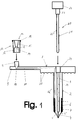
- the catheter has a circular disk-shaped plate 1 which is supported on the abdominal wall of the patient and from which a catheter tube 2 extends.
- the channel 3 of the catheter tube for supplying a nutrient solution into the gastric lumen is closed at its distal end with a lip valve 4, which has two lips 5, 5 'which extend from the distal end of the tube and lie closely on one another.
- the lip valve 4 does allow a fluid flow from the catheter tube 2 into the stomach lumen, but a reverse fluid flow is not possible.
- the circular disk-shaped support plate 1 and the catheter tube 2 with the lip valve 4 consist of a flexible material, preferably silicone. Numerous knobs 30 are provided on the underside of the support plate 1.
- annular space 6 is formed in the tube wall thereof, which is filled with a filling medium, e.g. Air or a liquid is filled, so that the catheter tube expands in the lower part like a balloon.
- Reference number 7 denotes the circumferential gluing point at which the lower end of the outer tube wall of the catheter tube slotted in the axial direction is glued to the inner tube wall to form the annular space.
- a flexible tab 8 with a rectangular cross section extends from the support plate 1 of the catheter and is integral with the support plate 1.
- a cylindrical connector part 9 is formed, which consists of a pierceable, self-sealing material, preferably the same material, for example silicone, as the support plate, the tab and the catheter tube.
- a cylindrical shaft 10 is formed in the cylindrical connector part 9, which opens into a channel 11 which extends through the tab 8 and the tube wall 12 of the catheter into the annular space 6.
- a cylindrical recess 24 is provided, which is followed by the channel 3 of the catheter tube 2 for supplying a nutrient solution.
- the inside diameter of the recess 24 corresponds to the outside diameter of the connector part 9 formed on the tab 8, so that it can be inserted into the recess to close the filling opening.
- the catheter assembly further comprises an adapter piece 13 for the connection of a syringe for inflating the balloon.
- One end piece of the adapter piece 13 is designed as a Luer lock connector 14 with a funnel-shaped recess 15 and an external thread 16, while the other end piece is provided with a cylindrical recess 17, so that the adapter piece 13 fits the cylindrical connector part 9 of the Leads catheter 1.
- the catheter-side connector part 9 and the recess 17 of the adapter piece 13 can also be conical.
- a pointed cannula 19 is inserted, which extends into the cylinder space 17 and creates a flow connection between the conical recess 15 and the cylindrical recess 17.
- the adapter piece 13 After insertion of the catheter tube 2, the adapter piece 13 is plugged onto the connector part 9 on the catheter side, the cannula 19 penetrating the connector part 9 and penetrating into the connector shaft 10 of the tab 8. A conventional syringe or a hose line with an air pump is connected to the Luer lock connecting part 14. Then the balloon is filled with air and the adapter piece 13 is pulled off again, the opening in the connector part 9 closing again in a self-sealing manner.
- the adapter piece 13 can also be integrated in a syringe or in the connecting part of a pump.
- the catheter arrangement also comprises a stylet 20, which consists of a round rod 21 provided with an external thread 20 ′ with a grip part 22. Below the grip part 22, the rod 21 of the stylet has a cylindrical shoulder 23 which, when the stylet is inserted, sits in the recess 24 in the center of the support plate 1.
- the channel 3 of the catheter tube 2 for supplying the nutrient solution is provided with an internal thread 25.
- FIG. 3 shows the distal end piece of the catheter tube 26 of a further embodiment of the catheter
- FIG. 4 shows the catheter in a top view.
- the catheter differs from that with reference to that shown in FIGS. 1 and 2 described embodiments in that two superimposed balloons are formed in the catheter tube, which can be inflated individually and allow an individual adjustment of the shaft length.
- Figs. 3 and 4 are the parts of the catheter which correspond to the parts of the embodiment according to FIGS. 1 and 2 correspond, provided with the same reference numerals.
- the two annular spaces 6 ', 6' 'of the balloons are each connected to a connector part via a channel in the hose wall 12 which cannot be seen in FIG. 3.
- the lower annular space 6 ' is connected to the connector part 9 on the tab 8 of the catheter.
- a second connector part 26 is provided on the support plate for filling the upper annular space 6 ′′ (FIG. 4).
- either the lower or the upper balloon can be inflated after inserting the catheter.
- FIG. 5 shows a section of a further embodiment of the catheter tube in the area of the annular space 6.
- the outer wall of the balloon consists of two layers 27, 28 of different materials lying one above the other.
- the inner layer 27 is made of a flexible sealing material and the outer layer 28 is made of a harder material than the inner layer.
- the two layers are not connected to one another in the area of the annular space.
- a gel-like material 29 is enclosed between the layers 27, 28 in order to increase the flexibility.
- the harder outer skin gives the balloon the necessary stability and resistance.
Landscapes
- Health & Medical Sciences (AREA)
- Life Sciences & Earth Sciences (AREA)
- Animal Behavior & Ethology (AREA)
- General Health & Medical Sciences (AREA)
- Public Health (AREA)
- Veterinary Medicine (AREA)
- Pulmonology (AREA)
- Gastroenterology & Hepatology (AREA)
- Infusion, Injection, And Reservoir Apparatuses (AREA)
- Medical Preparation Storing Or Oral Administration Devices (AREA)
- Pharmaceuticals Containing Other Organic And Inorganic Compounds (AREA)
- Media Introduction/Drainage Providing Device (AREA)
Applications Claiming Priority (2)
| Application Number | Priority Date | Filing Date | Title |
|---|---|---|---|
| DE19533749 | 1995-09-12 | ||
| DE19533749A DE19533749A1 (de) | 1995-09-12 | 1995-09-12 | Stoma-Gastrostomiesonde mit flacher Rückhalteplatte und optionaler variabler Schaftlänge |
Publications (2)
| Publication Number | Publication Date |
|---|---|
| EP0761198A1 true EP0761198A1 (fr) | 1997-03-12 |
| EP0761198B1 EP0761198B1 (fr) | 2001-12-12 |
Family
ID=7771946
Family Applications (1)
| Application Number | Title | Priority Date | Filing Date |
|---|---|---|---|
| EP96114109A Expired - Lifetime EP0761198B1 (fr) | 1995-09-12 | 1996-09-04 | Cathéter pour l'alimentation entérale par voie percutanée |
Country Status (7)
| Country | Link |
|---|---|
| EP (1) | EP0761198B1 (fr) |
| AT (1) | ATE210419T1 (fr) |
| DE (2) | DE19533749A1 (fr) |
| DK (1) | DK0761198T3 (fr) |
| ES (1) | ES2165949T3 (fr) |
| NO (1) | NO311331B1 (fr) |
| PT (1) | PT761198E (fr) |
Cited By (1)
| Publication number | Priority date | Publication date | Assignee | Title |
|---|---|---|---|---|
| WO2025083106A1 (fr) * | 2023-10-19 | 2025-04-24 | Fresenius Kabi Deutschland Gmbh | Cathéter entéral à dispositif d'auto-décompression intégré, et dispositif d'auto-décompression entéral |
Families Citing this family (2)
| Publication number | Priority date | Publication date | Assignee | Title |
|---|---|---|---|---|
| DE10055281B4 (de) | 2000-11-08 | 2004-12-23 | Fresenius Kabi Deutschland Gmbh | Adapter für eine PEG-Sonde |
| DE10131152B4 (de) * | 2001-04-30 | 2004-05-27 | Nutricia Healthcare S.A. | Medizinisches Ballon-Button-System |
Citations (5)
| Publication number | Priority date | Publication date | Assignee | Title |
|---|---|---|---|---|
| US4102342A (en) * | 1975-12-29 | 1978-07-25 | Taichiro Akiyama | Valved device |
| WO1990012611A1 (fr) * | 1989-04-21 | 1990-11-01 | Ash Medical Systems, Inc. | Dispositif d'acces pour perfusion non intravasculaire |
| WO1992019314A1 (fr) * | 1991-05-03 | 1992-11-12 | Bierman Steven F | Raccord de branchement lateral pour systeme de catheterisme |
| US5267969A (en) * | 1992-10-08 | 1993-12-07 | Abbott Laboratories | External retaining device for feeding tube or the like |
| WO1994015655A2 (fr) * | 1993-01-07 | 1994-07-21 | Medical Innovations Corporation | Systeme catheter pour gastrostomie |
-
1995
- 1995-09-12 DE DE19533749A patent/DE19533749A1/de not_active Withdrawn
-
1996
- 1996-08-28 NO NO19963590A patent/NO311331B1/no unknown
- 1996-09-04 ES ES96114109T patent/ES2165949T3/es not_active Expired - Lifetime
- 1996-09-04 DE DE59608419T patent/DE59608419D1/de not_active Expired - Fee Related
- 1996-09-04 AT AT96114109T patent/ATE210419T1/de not_active IP Right Cessation
- 1996-09-04 EP EP96114109A patent/EP0761198B1/fr not_active Expired - Lifetime
- 1996-09-04 PT PT96114109T patent/PT761198E/pt unknown
- 1996-09-04 DK DK96114109T patent/DK0761198T3/da active
Patent Citations (5)
| Publication number | Priority date | Publication date | Assignee | Title |
|---|---|---|---|---|
| US4102342A (en) * | 1975-12-29 | 1978-07-25 | Taichiro Akiyama | Valved device |
| WO1990012611A1 (fr) * | 1989-04-21 | 1990-11-01 | Ash Medical Systems, Inc. | Dispositif d'acces pour perfusion non intravasculaire |
| WO1992019314A1 (fr) * | 1991-05-03 | 1992-11-12 | Bierman Steven F | Raccord de branchement lateral pour systeme de catheterisme |
| US5267969A (en) * | 1992-10-08 | 1993-12-07 | Abbott Laboratories | External retaining device for feeding tube or the like |
| WO1994015655A2 (fr) * | 1993-01-07 | 1994-07-21 | Medical Innovations Corporation | Systeme catheter pour gastrostomie |
Cited By (1)
| Publication number | Priority date | Publication date | Assignee | Title |
|---|---|---|---|---|
| WO2025083106A1 (fr) * | 2023-10-19 | 2025-04-24 | Fresenius Kabi Deutschland Gmbh | Cathéter entéral à dispositif d'auto-décompression intégré, et dispositif d'auto-décompression entéral |
Also Published As
| Publication number | Publication date |
|---|---|
| DE59608419D1 (de) | 2002-01-24 |
| EP0761198B1 (fr) | 2001-12-12 |
| PT761198E (pt) | 2002-05-31 |
| NO963590D0 (no) | 1996-08-28 |
| NO963590L (no) | 1997-03-13 |
| NO311331B1 (no) | 2001-11-19 |
| ATE210419T1 (de) | 2001-12-15 |
| DE19533749A1 (de) | 1997-03-13 |
| DK0761198T3 (da) | 2002-03-18 |
| ES2165949T3 (es) | 2002-04-01 |
Similar Documents
| Publication | Publication Date | Title |
|---|---|---|
| DE69728281T2 (de) | Vorrichtung für den chirurgischen Zugang zu einer Körperhöhle | |
| DE60013092T2 (de) | Ballonkatheter für den Magen mit verbesserter Ballonorientierung | |
| DE68916960T2 (de) | Einen ballon aufweisendes instrument zum kontinuierlichen injizieren einer medizinischen flüssigkeit. | |
| DE60112550T2 (de) | Implantierbare vorrichtung zur arzneimittelinjektion | |
| DE68911651T2 (de) | Subkutan implantierter katheterzusammenbau. | |
| DE4105661C2 (fr) | ||
| DE60030451T2 (de) | Einstellbares magenimplantat | |
| DE69631045T2 (de) | Gastrostomie-Ernährungsanschlüsse mit einwandfrei abdichtenden Eintrittsventilen | |
| DE69828281T2 (de) | Subkutaninfusionsvorrichtung | |
| DE69124164T2 (de) | Implantierbare infusionsvorrichtung | |
| DE69221904T2 (de) | Katheter mit zweirichtungsventil | |
| DE60112554T2 (de) | Intragastrale vorrichtung zur behandlung der morbiden fettsucht | |
| DE69022989T2 (de) | Injektor mit ballon zur kontinuierlichen injektion einer arzneimittellösung. | |
| DE1675448A1 (de) | Einweg-Durchflussventil | |
| WO1995029661A1 (fr) | Distributeur fait d'une seule piece pour l'administration sans contamination de medicaments (cytostatiques) | |
| DE102009016373A1 (de) | Verbindungsstück für den Sondenschlauch einer enteralen Ernährungssonde und Anordnung aus einer enteralen Ernährungssonde und einem enteralen Überleitsystem | |
| EP1331962B1 (fr) | Adaptateur pour une sonde peg | |
| EP1331912B1 (fr) | Adaptateur pour sonde de gastrostomie endoscopique percutanee | |
| DE19634116C2 (de) | Katheter für die perkutane enterale Ernährung | |
| DE69720400T2 (de) | Gastrostomieröhre für enterale Ernährung | |
| EP2931135B1 (fr) | Cathéter à ballon pour le traitement de fistules entéro-atmosphériques en abdomen ouvert | |
| WO2003013644A2 (fr) | Piece de montage pour un adaptateur d'une sonde de gastrostomie endoscopique percutanee et adaptateur pour sonde de gastrostomie endoscopique percutanee comprenant une telle piece de montage | |
| EP0761198B1 (fr) | Cathéter pour l'alimentation entérale par voie percutanée | |
| DE8807003U1 (de) | Katheter zur Organperfusion | |
| DE2918326A1 (de) | Mit einer kunststoffkanuele verbundenes anschlusstueck |
Legal Events
| Date | Code | Title | Description |
|---|---|---|---|
| PUAI | Public reference made under article 153(3) epc to a published international application that has entered the european phase |
Free format text: ORIGINAL CODE: 0009012 |
|
| AK | Designated contracting states |
Kind code of ref document: A1 Designated state(s): AT BE CH DE DK ES FI FR GB GR IE IT LI LU NL PT SE |
|
| 17P | Request for examination filed |
Effective date: 19970715 |
|
| GRAG | Despatch of communication of intention to grant |
Free format text: ORIGINAL CODE: EPIDOS AGRA |
|
| 17Q | First examination report despatched |
Effective date: 20001103 |
|
| GRAG | Despatch of communication of intention to grant |
Free format text: ORIGINAL CODE: EPIDOS AGRA |
|
| GRAG | Despatch of communication of intention to grant |
Free format text: ORIGINAL CODE: EPIDOS AGRA |
|
| GRAH | Despatch of communication of intention to grant a patent |
Free format text: ORIGINAL CODE: EPIDOS IGRA |
|
| RBV | Designated contracting states (corrected) |
Designated state(s): AT BE CH DE DK ES FI FR GB GR IE IT LI LU NL PT SE |
|
| GRAH | Despatch of communication of intention to grant a patent |
Free format text: ORIGINAL CODE: EPIDOS IGRA |
|
| GRAA | (expected) grant |
Free format text: ORIGINAL CODE: 0009210 |
|
| AK | Designated contracting states |
Kind code of ref document: B1 Designated state(s): AT BE CH DE DK ES FI FR GB GR IE IT LI LU NL PT SE |
|
| REF | Corresponds to: |
Ref document number: 210419 Country of ref document: AT Date of ref document: 20011215 Kind code of ref document: T |
|
| REG | Reference to a national code |
Ref country code: CH Ref legal event code: EP |
|
| REG | Reference to a national code |
Ref country code: GB Ref legal event code: IF02 |
|
| REG | Reference to a national code |
Ref country code: IE Ref legal event code: FG4D Free format text: GERMAN |
|
| REF | Corresponds to: |
Ref document number: 59608419 Country of ref document: DE Date of ref document: 20020124 |
|
| REG | Reference to a national code |
Ref country code: DK Ref legal event code: T3 |
|
| GBT | Gb: translation of ep patent filed (gb section 77(6)(a)/1977) |
Effective date: 20020225 |
|
| REG | Reference to a national code |
Ref country code: ES Ref legal event code: FG2A Ref document number: 2165949 Country of ref document: ES Kind code of ref document: T3 |
|
| ET | Fr: translation filed | ||
| REG | Reference to a national code |
Ref country code: PT Ref legal event code: SC4A Free format text: AVAILABILITY OF NATIONAL TRANSLATION Effective date: 20020306 |
|
| REG | Reference to a national code |
Ref country code: GR Ref legal event code: EP Ref document number: 20020400973 Country of ref document: GR |
|
| PGFP | Annual fee paid to national office [announced via postgrant information from national office to epo] |
Ref country code: GB Payment date: 20020814 Year of fee payment: 7 |
|
| PGFP | Annual fee paid to national office [announced via postgrant information from national office to epo] |
Ref country code: GR Payment date: 20020822 Year of fee payment: 7 |
|
| PGFP | Annual fee paid to national office [announced via postgrant information from national office to epo] |
Ref country code: IE Payment date: 20020826 Year of fee payment: 7 |
|
| PGFP | Annual fee paid to national office [announced via postgrant information from national office to epo] |
Ref country code: PT Payment date: 20020904 Year of fee payment: 7 |
|
| PGFP | Annual fee paid to national office [announced via postgrant information from national office to epo] |
Ref country code: NL Payment date: 20020916 Year of fee payment: 7 Ref country code: FR Payment date: 20020916 Year of fee payment: 7 |
|
| PGFP | Annual fee paid to national office [announced via postgrant information from national office to epo] |
Ref country code: DK Payment date: 20020918 Year of fee payment: 7 |
|
| PGFP | Annual fee paid to national office [announced via postgrant information from national office to epo] |
Ref country code: AT Payment date: 20020919 Year of fee payment: 7 |
|
| PGFP | Annual fee paid to national office [announced via postgrant information from national office to epo] |
Ref country code: SE Payment date: 20020920 Year of fee payment: 7 Ref country code: FI Payment date: 20020920 Year of fee payment: 7 Ref country code: CH Payment date: 20020920 Year of fee payment: 7 Ref country code: BE Payment date: 20020920 Year of fee payment: 7 |
|
| PGFP | Annual fee paid to national office [announced via postgrant information from national office to epo] |
Ref country code: LU Payment date: 20020923 Year of fee payment: 7 |
|
| PGFP | Annual fee paid to national office [announced via postgrant information from national office to epo] |
Ref country code: ES Payment date: 20020926 Year of fee payment: 7 |
|
| PLBE | No opposition filed within time limit |
Free format text: ORIGINAL CODE: 0009261 |
|
| STAA | Information on the status of an ep patent application or granted ep patent |
Free format text: STATUS: NO OPPOSITION FILED WITHIN TIME LIMIT |
|
| PGFP | Annual fee paid to national office [announced via postgrant information from national office to epo] |
Ref country code: DE Payment date: 20021116 Year of fee payment: 7 |
|
| 26N | No opposition filed | ||
| PG25 | Lapsed in a contracting state [announced via postgrant information from national office to epo] |
Ref country code: LU Free format text: LAPSE BECAUSE OF NON-PAYMENT OF DUE FEES Effective date: 20030904 Ref country code: IE Free format text: LAPSE BECAUSE OF NON-PAYMENT OF DUE FEES Effective date: 20030904 Ref country code: GB Free format text: LAPSE BECAUSE OF NON-PAYMENT OF DUE FEES Effective date: 20030904 Ref country code: FI Free format text: LAPSE BECAUSE OF NON-PAYMENT OF DUE FEES Effective date: 20030904 Ref country code: AT Free format text: LAPSE BECAUSE OF NON-PAYMENT OF DUE FEES Effective date: 20030904 |
|
| PG25 | Lapsed in a contracting state [announced via postgrant information from national office to epo] |
Ref country code: SE Free format text: LAPSE BECAUSE OF NON-PAYMENT OF DUE FEES Effective date: 20030905 Ref country code: ES Free format text: LAPSE BECAUSE OF NON-PAYMENT OF DUE FEES Effective date: 20030905 |
|
| PG25 | Lapsed in a contracting state [announced via postgrant information from national office to epo] |
Ref country code: LI Free format text: LAPSE BECAUSE OF NON-PAYMENT OF DUE FEES Effective date: 20030930 Ref country code: DK Free format text: LAPSE BECAUSE OF NON-PAYMENT OF DUE FEES Effective date: 20030930 Ref country code: CH Free format text: LAPSE BECAUSE OF NON-PAYMENT OF DUE FEES Effective date: 20030930 Ref country code: BE Free format text: LAPSE BECAUSE OF NON-PAYMENT OF DUE FEES Effective date: 20030930 |
|
| BERE | Be: lapsed |
Owner name: *FRESENIUS A.G. Effective date: 20030930 |
|
| PG25 | Lapsed in a contracting state [announced via postgrant information from national office to epo] |
Ref country code: PT Free format text: LAPSE BECAUSE OF NON-PAYMENT OF DUE FEES Effective date: 20040331 |
|
| PG25 | Lapsed in a contracting state [announced via postgrant information from national office to epo] |
Ref country code: NL Free format text: LAPSE BECAUSE OF NON-PAYMENT OF DUE FEES Effective date: 20040401 Ref country code: DE Free format text: LAPSE BECAUSE OF NON-PAYMENT OF DUE FEES Effective date: 20040401 |
|
| PG25 | Lapsed in a contracting state [announced via postgrant information from national office to epo] |
Ref country code: GR Free format text: LAPSE BECAUSE OF NON-PAYMENT OF DUE FEES Effective date: 20040402 |
|
| GBPC | Gb: european patent ceased through non-payment of renewal fee | ||
| EUG | Se: european patent has lapsed | ||
| REG | Reference to a national code |
Ref country code: DK Ref legal event code: EBP |
|
| REG | Reference to a national code |
Ref country code: CH Ref legal event code: PL |
|
| PG25 | Lapsed in a contracting state [announced via postgrant information from national office to epo] |
Ref country code: FR Free format text: LAPSE BECAUSE OF NON-PAYMENT OF DUE FEES Effective date: 20040528 |
|
| NLV4 | Nl: lapsed or anulled due to non-payment of the annual fee |
Effective date: 20040401 |
|
| REG | Reference to a national code |
Ref country code: PT Ref legal event code: MM4A Free format text: LAPSE DUE TO NON-PAYMENT OF FEES Effective date: 20040331 Ref country code: IE Ref legal event code: MM4A |
|
| REG | Reference to a national code |
Ref country code: FR Ref legal event code: ST |
|
| REG | Reference to a national code |
Ref country code: ES Ref legal event code: FD2A Effective date: 20030905 |
|
| PG25 | Lapsed in a contracting state [announced via postgrant information from national office to epo] |
Ref country code: IT Free format text: LAPSE BECAUSE OF NON-PAYMENT OF DUE FEES Effective date: 20050904 |