EP0761288A1 - Vorrichtung und Verfahren zur Reinigung von Gasen, die halogenierte Verbindungen enthalten - Google Patents
Vorrichtung und Verfahren zur Reinigung von Gasen, die halogenierte Verbindungen enthalten Download PDFInfo
- Publication number
- EP0761288A1 EP0761288A1 EP96108745A EP96108745A EP0761288A1 EP 0761288 A1 EP0761288 A1 EP 0761288A1 EP 96108745 A EP96108745 A EP 96108745A EP 96108745 A EP96108745 A EP 96108745A EP 0761288 A1 EP0761288 A1 EP 0761288A1
- Authority
- EP
- European Patent Office
- Prior art keywords
- ozone
- gas
- climate
- depleting
- valve
- Prior art date
- Legal status (The legal status is an assumption and is not a legal conclusion. Google has not performed a legal analysis and makes no representation as to the accuracy of the status listed.)
- Granted
Links
- 239000007789 gas Substances 0.000 title claims abstract description 94
- 150000001875 compounds Chemical class 0.000 title claims description 48
- 238000000034 method Methods 0.000 title claims description 12
- 238000004140 cleaning Methods 0.000 title claims description 7
- 238000001179 sorption measurement Methods 0.000 claims abstract description 43
- 239000007787 solid Substances 0.000 claims abstract description 6
- 239000002594 sorbent Substances 0.000 claims description 48
- 238000010438 heat treatment Methods 0.000 claims description 32
- IJGRMHOSHXDMSA-UHFFFAOYSA-N Atomic nitrogen Chemical compound N#N IJGRMHOSHXDMSA-UHFFFAOYSA-N 0.000 claims description 22
- 238000000354 decomposition reaction Methods 0.000 claims description 13
- 230000008878 coupling Effects 0.000 claims description 12
- 238000010168 coupling process Methods 0.000 claims description 12
- 238000005859 coupling reaction Methods 0.000 claims description 12
- 229910052757 nitrogen Inorganic materials 0.000 claims description 11
- 239000012159 carrier gas Substances 0.000 claims description 10
- 238000000746 purification Methods 0.000 claims description 4
- 239000011261 inert gas Substances 0.000 claims description 3
- CBENFWSGALASAD-UHFFFAOYSA-N Ozone Chemical class [O-][O+]=O CBENFWSGALASAD-UHFFFAOYSA-N 0.000 abstract description 5
- 150000002366 halogen compounds Chemical class 0.000 abstract 3
- XPDWGBQVDMORPB-UHFFFAOYSA-N Fluoroform Chemical compound FC(F)F XPDWGBQVDMORPB-UHFFFAOYSA-N 0.000 description 8
- 230000002093 peripheral effect Effects 0.000 description 8
- 239000004065 semiconductor Substances 0.000 description 8
- UQSXHKLRYXJYBZ-UHFFFAOYSA-N Iron oxide Chemical compound [Fe]=O UQSXHKLRYXJYBZ-UHFFFAOYSA-N 0.000 description 6
- 238000011144 upstream manufacturing Methods 0.000 description 6
- 229910052500 inorganic mineral Inorganic materials 0.000 description 5
- 239000011707 mineral Substances 0.000 description 5
- RWRIWBAIICGTTQ-UHFFFAOYSA-N difluoromethane Chemical compound FCF RWRIWBAIICGTTQ-UHFFFAOYSA-N 0.000 description 4
- 238000001312 dry etching Methods 0.000 description 4
- 238000007789 sealing Methods 0.000 description 4
- TXEYQDLBPFQVAA-UHFFFAOYSA-N tetrafluoromethane Chemical compound FC(F)(F)F TXEYQDLBPFQVAA-UHFFFAOYSA-N 0.000 description 4
- 239000012855 volatile organic compound Substances 0.000 description 4
- YCKRFDGAMUMZLT-UHFFFAOYSA-N Fluorine atom Chemical compound [F] YCKRFDGAMUMZLT-UHFFFAOYSA-N 0.000 description 3
- 229910018503 SF6 Inorganic materials 0.000 description 3
- CUPCBVUMRUSXIU-UHFFFAOYSA-N [Fe].OOO Chemical compound [Fe].OOO CUPCBVUMRUSXIU-UHFFFAOYSA-N 0.000 description 3
- 239000011737 fluorine Substances 0.000 description 3
- 229910052731 fluorine Inorganic materials 0.000 description 3
- WMIYKQLTONQJES-UHFFFAOYSA-N hexafluoroethane Chemical compound FC(F)(F)C(F)(F)F WMIYKQLTONQJES-UHFFFAOYSA-N 0.000 description 3
- 239000011810 insulating material Substances 0.000 description 3
- XEEYBQQBJWHFJM-UHFFFAOYSA-N iron Substances [Fe] XEEYBQQBJWHFJM-UHFFFAOYSA-N 0.000 description 3
- 229910021519 iron(III) oxide-hydroxide Inorganic materials 0.000 description 3
- QKCGXXHCELUCKW-UHFFFAOYSA-N n-[4-[4-(dinaphthalen-2-ylamino)phenyl]phenyl]-n-naphthalen-2-ylnaphthalen-2-amine Chemical compound C1=CC=CC2=CC(N(C=3C=CC(=CC=3)C=3C=CC(=CC=3)N(C=3C=C4C=CC=CC4=CC=3)C=3C=C4C=CC=CC4=CC=3)C3=CC4=CC=CC=C4C=C3)=CC=C21 QKCGXXHCELUCKW-UHFFFAOYSA-N 0.000 description 3
- 239000000126 substance Substances 0.000 description 3
- SFZCNBIFKDRMGX-UHFFFAOYSA-N sulfur hexafluoride Chemical compound FS(F)(F)(F)(F)F SFZCNBIFKDRMGX-UHFFFAOYSA-N 0.000 description 3
- 229960000909 sulfur hexafluoride Drugs 0.000 description 3
- -1 1,1-dichlorodifluoroethylene, chlorotrifluoroethylene Chemical group 0.000 description 2
- 229920004449 Halon® Polymers 0.000 description 2
- 229920006926 PFC Polymers 0.000 description 2
- XUIMIQQOPSSXEZ-UHFFFAOYSA-N Silicon Chemical compound [Si] XUIMIQQOPSSXEZ-UHFFFAOYSA-N 0.000 description 2
- 235000012216 bentonite Nutrition 0.000 description 2
- 150000008280 chlorinated hydrocarbons Chemical class 0.000 description 2
- 239000000567 combustion gas Substances 0.000 description 2
- 238000002485 combustion reaction Methods 0.000 description 2
- 150000008282 halocarbons Chemical class 0.000 description 2
- 238000009413 insulation Methods 0.000 description 2
- 229910052742 iron Inorganic materials 0.000 description 2
- 238000004519 manufacturing process Methods 0.000 description 2
- 229910052618 mica group Inorganic materials 0.000 description 2
- 229910052615 phyllosilicate Inorganic materials 0.000 description 2
- 229910052710 silicon Inorganic materials 0.000 description 2
- 239000010703 silicon Substances 0.000 description 2
- VZGDMQKNWNREIO-UHFFFAOYSA-N tetrachloromethane Chemical compound ClC(Cl)(Cl)Cl VZGDMQKNWNREIO-UHFFFAOYSA-N 0.000 description 2
- 231100000925 very toxic Toxicity 0.000 description 2
- 235000012431 wafers Nutrition 0.000 description 2
- UOCLXMDMGBRAIB-UHFFFAOYSA-N 1,1,1-trichloroethane Chemical compound CC(Cl)(Cl)Cl UOCLXMDMGBRAIB-UHFFFAOYSA-N 0.000 description 1
- UJPMYEOUBPIPHQ-UHFFFAOYSA-N 1,1,1-trifluoroethane Chemical compound CC(F)(F)F UJPMYEOUBPIPHQ-UHFFFAOYSA-N 0.000 description 1
- UGCSPKPEHQEOSR-UHFFFAOYSA-N 1,1,2,2-tetrachloro-1,2-difluoroethane Chemical compound FC(Cl)(Cl)C(F)(Cl)Cl UGCSPKPEHQEOSR-UHFFFAOYSA-N 0.000 description 1
- AJDIZQLSFPQPEY-UHFFFAOYSA-N 1,1,2-Trichlorotrifluoroethane Chemical compound FC(F)(Cl)C(F)(Cl)Cl AJDIZQLSFPQPEY-UHFFFAOYSA-N 0.000 description 1
- BQCIDUSAKPWEOX-UHFFFAOYSA-N 1,1-Difluoroethene Chemical compound FC(F)=C BQCIDUSAKPWEOX-UHFFFAOYSA-N 0.000 description 1
- NPNPZTNLOVBDOC-UHFFFAOYSA-N 1,1-difluoroethane Chemical compound CC(F)F NPNPZTNLOVBDOC-UHFFFAOYSA-N 0.000 description 1
- DPOZWTRVXPUOQW-UHFFFAOYSA-N 1,2-dibromo-1,1-difluoroethane Chemical compound FC(F)(Br)CBr DPOZWTRVXPUOQW-UHFFFAOYSA-N 0.000 description 1
- DDMOUSALMHHKOS-UHFFFAOYSA-N 1,2-dichloro-1,1,2,2-tetrafluoroethane Chemical compound FC(F)(Cl)C(F)(F)Cl DDMOUSALMHHKOS-UHFFFAOYSA-N 0.000 description 1
- RFCAUADVODFSLZ-UHFFFAOYSA-N 1-Chloro-1,1,2,2,2-pentafluoroethane Chemical compound FC(F)(F)C(F)(F)Cl RFCAUADVODFSLZ-UHFFFAOYSA-N 0.000 description 1
- BHNZEZWIUMJCGF-UHFFFAOYSA-N 1-chloro-1,1-difluoroethane Chemical compound CC(F)(F)Cl BHNZEZWIUMJCGF-UHFFFAOYSA-N 0.000 description 1
- CYXIKYKBLDZZNW-UHFFFAOYSA-N 2-Chloro-1,1,1-trifluoroethane Chemical compound FC(F)(F)CCl CYXIKYKBLDZZNW-UHFFFAOYSA-N 0.000 description 1
- 239000005995 Aluminium silicate Substances 0.000 description 1
- VOPWNXZWBYDODV-UHFFFAOYSA-N Chlorodifluoromethane Chemical compound FC(F)Cl VOPWNXZWBYDODV-UHFFFAOYSA-N 0.000 description 1
- 239000004340 Chloropentafluoroethane Substances 0.000 description 1
- 239000004338 Dichlorodifluoromethane Substances 0.000 description 1
- ZJCFOZHHYJVNNP-UHFFFAOYSA-N F[C]Br Chemical compound F[C]Br ZJCFOZHHYJVNNP-UHFFFAOYSA-N 0.000 description 1
- 241001595840 Margarites Species 0.000 description 1
- 239000004341 Octafluorocyclobutane Substances 0.000 description 1
- 238000010521 absorption reaction Methods 0.000 description 1
- 238000004887 air purification Methods 0.000 description 1
- WYTGDNHDOZPMIW-RCBQFDQVSA-N alstonine Natural products C1=CC2=C3C=CC=CC3=NC2=C2N1C[C@H]1[C@H](C)OC=C(C(=O)OC)[C@H]1C2 WYTGDNHDOZPMIW-RCBQFDQVSA-N 0.000 description 1
- 235000012211 aluminium silicate Nutrition 0.000 description 1
- 229910000278 bentonite Inorganic materials 0.000 description 1
- 239000000440 bentonite Substances 0.000 description 1
- SVPXDRXYRYOSEX-UHFFFAOYSA-N bentoquatam Chemical compound O.O=[Si]=O.O=[Al]O[Al]=O SVPXDRXYRYOSEX-UHFFFAOYSA-N 0.000 description 1
- 229910052626 biotite Inorganic materials 0.000 description 1
- MEXUFEQDCXZEON-UHFFFAOYSA-N bromochlorodifluoromethane Chemical compound FC(F)(Cl)Br MEXUFEQDCXZEON-UHFFFAOYSA-N 0.000 description 1
- RJCQBQGAPKAMLL-UHFFFAOYSA-N bromotrifluoromethane Chemical compound FC(F)(F)Br RJCQBQGAPKAMLL-UHFFFAOYSA-N 0.000 description 1
- 125000004432 carbon atom Chemical group C* 0.000 description 1
- IYRWEQXVUNLMAY-UHFFFAOYSA-N carbonyl fluoride Chemical compound FC(F)=O IYRWEQXVUNLMAY-UHFFFAOYSA-N 0.000 description 1
- 229910052862 chloritoid Inorganic materials 0.000 description 1
- KYKAJFCTULSVSH-UHFFFAOYSA-N chloro(fluoro)methane Chemical compound F[C]Cl KYKAJFCTULSVSH-UHFFFAOYSA-N 0.000 description 1
- 150000005827 chlorofluoro hydrocarbons Chemical class 0.000 description 1
- 235000019406 chloropentafluoroethane Nutrition 0.000 description 1
- UUAGAQFQZIEFAH-UHFFFAOYSA-N chlorotrifluoroethylene Chemical compound FC(F)=C(F)Cl UUAGAQFQZIEFAH-UHFFFAOYSA-N 0.000 description 1
- AFYPFACVUDMOHA-UHFFFAOYSA-N chlorotrifluoromethane Chemical compound FC(F)(F)Cl AFYPFACVUDMOHA-UHFFFAOYSA-N 0.000 description 1
- 239000004927 clay Substances 0.000 description 1
- 230000006835 compression Effects 0.000 description 1
- 238000007906 compression Methods 0.000 description 1
- 238000010586 diagram Methods 0.000 description 1
- GUJOJGAPFQRJSV-UHFFFAOYSA-N dialuminum;dioxosilane;oxygen(2-);hydrate Chemical compound O.[O-2].[O-2].[O-2].[Al+3].[Al+3].O=[Si]=O.O=[Si]=O.O=[Si]=O.O=[Si]=O GUJOJGAPFQRJSV-UHFFFAOYSA-N 0.000 description 1
- AZSZCFSOHXEJQE-UHFFFAOYSA-N dibromodifluoromethane Chemical compound FC(F)(Br)Br AZSZCFSOHXEJQE-UHFFFAOYSA-N 0.000 description 1
- KVBKAPANDHPRDG-UHFFFAOYSA-N dibromotetrafluoroethane Chemical compound FC(F)(Br)C(F)(F)Br KVBKAPANDHPRDG-UHFFFAOYSA-N 0.000 description 1
- PXBRQCKWGAHEHS-UHFFFAOYSA-N dichlorodifluoromethane Chemical compound FC(F)(Cl)Cl PXBRQCKWGAHEHS-UHFFFAOYSA-N 0.000 description 1
- 235000019404 dichlorodifluoromethane Nutrition 0.000 description 1
- UMNKXPULIDJLSU-UHFFFAOYSA-N dichlorofluoromethane Chemical compound FC(Cl)Cl UMNKXPULIDJLSU-UHFFFAOYSA-N 0.000 description 1
- 229940099364 dichlorofluoromethane Drugs 0.000 description 1
- YGANSGVIUGARFR-UHFFFAOYSA-N dipotassium dioxosilane oxo(oxoalumanyloxy)alumane oxygen(2-) Chemical compound [O--].[K+].[K+].O=[Si]=O.O=[Al]O[Al]=O YGANSGVIUGARFR-UHFFFAOYSA-N 0.000 description 1
- 238000005485 electric heating Methods 0.000 description 1
- 238000005265 energy consumption Methods 0.000 description 1
- 238000005516 engineering process Methods 0.000 description 1
- 238000005530 etching Methods 0.000 description 1
- 229910052598 goethite Inorganic materials 0.000 description 1
- 239000008187 granular material Substances 0.000 description 1
- 238000005338 heat storage Methods 0.000 description 1
- 229910052595 hematite Inorganic materials 0.000 description 1
- 239000011019 hematite Substances 0.000 description 1
- AEIXRCIKZIZYPM-UHFFFAOYSA-M hydroxy(oxo)iron Chemical compound [O][Fe]O AEIXRCIKZIZYPM-UHFFFAOYSA-M 0.000 description 1
- 229910052900 illite Inorganic materials 0.000 description 1
- LIKBJVNGSGBSGK-UHFFFAOYSA-N iron(3+);oxygen(2-) Chemical compound [O-2].[O-2].[O-2].[Fe+3].[Fe+3] LIKBJVNGSGBSGK-UHFFFAOYSA-N 0.000 description 1
- SZVJSHCCFOBDDC-UHFFFAOYSA-N iron(II,III) oxide Inorganic materials O=[Fe]O[Fe]O[Fe]=O SZVJSHCCFOBDDC-UHFFFAOYSA-N 0.000 description 1
- JEIPFZHSYJVQDO-UHFFFAOYSA-N iron(III) oxide Inorganic materials O=[Fe]O[Fe]=O JEIPFZHSYJVQDO-UHFFFAOYSA-N 0.000 description 1
- NLYAJNPCOHFWQQ-UHFFFAOYSA-N kaolin Chemical compound O.O.O=[Al]O[Si](=O)O[Si](=O)O[Al]=O NLYAJNPCOHFWQQ-UHFFFAOYSA-N 0.000 description 1
- 229910052629 lepidolite Inorganic materials 0.000 description 1
- 229910052630 margarite Inorganic materials 0.000 description 1
- 239000000463 material Substances 0.000 description 1
- 229910052901 montmorillonite Inorganic materials 0.000 description 1
- 229910052627 muscovite Inorganic materials 0.000 description 1
- VGIBGUSAECPPNB-UHFFFAOYSA-L nonaaluminum;magnesium;tripotassium;1,3-dioxido-2,4,5-trioxa-1,3-disilabicyclo[1.1.1]pentane;iron(2+);oxygen(2-);fluoride;hydroxide Chemical compound [OH-].[O-2].[O-2].[O-2].[O-2].[O-2].[F-].[Mg+2].[Al+3].[Al+3].[Al+3].[Al+3].[Al+3].[Al+3].[Al+3].[Al+3].[Al+3].[K+].[K+].[K+].[Fe+2].O1[Si]2([O-])O[Si]1([O-])O2.O1[Si]2([O-])O[Si]1([O-])O2.O1[Si]2([O-])O[Si]1([O-])O2.O1[Si]2([O-])O[Si]1([O-])O2.O1[Si]2([O-])O[Si]1([O-])O2.O1[Si]2([O-])O[Si]1([O-])O2.O1[Si]2([O-])O[Si]1([O-])O2 VGIBGUSAECPPNB-UHFFFAOYSA-L 0.000 description 1
- 229910000273 nontronite Inorganic materials 0.000 description 1
- BCCOBQSFUDVTJQ-UHFFFAOYSA-N octafluorocyclobutane Chemical compound FC1(F)C(F)(F)C(F)(F)C1(F)F BCCOBQSFUDVTJQ-UHFFFAOYSA-N 0.000 description 1
- 235000019407 octafluorocyclobutane Nutrition 0.000 description 1
- QYSGYZVSCZSLHT-UHFFFAOYSA-N octafluoropropane Chemical compound FC(F)(F)C(F)(F)C(F)(F)F QYSGYZVSCZSLHT-UHFFFAOYSA-N 0.000 description 1
- 238000010422 painting Methods 0.000 description 1
- 229910001737 paragonite Inorganic materials 0.000 description 1
- KAVGMUDTWQVPDF-UHFFFAOYSA-N perflubutane Chemical compound FC(F)(F)C(F)(F)C(F)(F)C(F)(F)F KAVGMUDTWQVPDF-UHFFFAOYSA-N 0.000 description 1
- 229950003332 perflubutane Drugs 0.000 description 1
- 229960004065 perflutren Drugs 0.000 description 1
- 229910052628 phlogopite Inorganic materials 0.000 description 1
- 230000001172 regenerating effect Effects 0.000 description 1
- 150000003839 salts Chemical class 0.000 description 1
- 229910000275 saponite Inorganic materials 0.000 description 1
- ABTOQLMXBSRXSM-UHFFFAOYSA-N silicon tetrafluoride Chemical compound F[Si](F)(F)F ABTOQLMXBSRXSM-UHFFFAOYSA-N 0.000 description 1
- 239000011232 storage material Substances 0.000 description 1
- 239000005437 stratosphere Substances 0.000 description 1
- 239000000758 substrate Substances 0.000 description 1
- 239000000454 talc Substances 0.000 description 1
- 229910052623 talc Inorganic materials 0.000 description 1
- CYRMSUTZVYGINF-UHFFFAOYSA-N trichlorofluoromethane Chemical compound FC(Cl)(Cl)Cl CYRMSUTZVYGINF-UHFFFAOYSA-N 0.000 description 1
- 229940029284 trichlorofluoromethane Drugs 0.000 description 1
- 238000010792 warming Methods 0.000 description 1
Images

Classifications
-
- B—PERFORMING OPERATIONS; TRANSPORTING
- B01—PHYSICAL OR CHEMICAL PROCESSES OR APPARATUS IN GENERAL
- B01D—SEPARATION
- B01D53/00—Separation of gases or vapours; Recovering vapours of volatile solvents from gases; Chemical or biological purification of waste gases, e.g. engine exhaust gases, smoke, fumes, flue gases, aerosols
- B01D53/34—Chemical or biological purification of waste gases
- B01D53/46—Removing components of defined structure
- B01D53/68—Halogens or halogen compounds
- B01D53/70—Organic halogen compounds
-
- B—PERFORMING OPERATIONS; TRANSPORTING
- B01—PHYSICAL OR CHEMICAL PROCESSES OR APPARATUS IN GENERAL
- B01D—SEPARATION
- B01D53/00—Separation of gases or vapours; Recovering vapours of volatile solvents from gases; Chemical or biological purification of waste gases, e.g. engine exhaust gases, smoke, fumes, flue gases, aerosols
- B01D53/02—Separation of gases or vapours; Recovering vapours of volatile solvents from gases; Chemical or biological purification of waste gases, e.g. engine exhaust gases, smoke, fumes, flue gases, aerosols by adsorption, e.g. preparative gas chromatography
- B01D53/04—Separation of gases or vapours; Recovering vapours of volatile solvents from gases; Chemical or biological purification of waste gases, e.g. engine exhaust gases, smoke, fumes, flue gases, aerosols by adsorption, e.g. preparative gas chromatography with stationary adsorbents
- B01D53/0462—Temperature swing adsorption
-
- B—PERFORMING OPERATIONS; TRANSPORTING
- B01—PHYSICAL OR CHEMICAL PROCESSES OR APPARATUS IN GENERAL
- B01D—SEPARATION
- B01D2251/00—Reactants
- B01D2251/60—Inorganic bases or salts
-
- B—PERFORMING OPERATIONS; TRANSPORTING
- B01—PHYSICAL OR CHEMICAL PROCESSES OR APPARATUS IN GENERAL
- B01D—SEPARATION
- B01D2253/00—Adsorbents used in seperation treatment of gases and vapours
- B01D2253/10—Inorganic adsorbents
- B01D2253/112—Metals or metal compounds not provided for in B01D2253/104 or B01D2253/106
- B01D2253/1124—Metal oxides
-
- B—PERFORMING OPERATIONS; TRANSPORTING
- B01—PHYSICAL OR CHEMICAL PROCESSES OR APPARATUS IN GENERAL
- B01D—SEPARATION
- B01D2257/00—Components to be removed
- B01D2257/10—Single element gases other than halogens
- B01D2257/106—Ozone
-
- B—PERFORMING OPERATIONS; TRANSPORTING
- B01—PHYSICAL OR CHEMICAL PROCESSES OR APPARATUS IN GENERAL
- B01D—SEPARATION
- B01D2257/00—Components to be removed
- B01D2257/20—Halogens or halogen compounds
-
- B—PERFORMING OPERATIONS; TRANSPORTING
- B01—PHYSICAL OR CHEMICAL PROCESSES OR APPARATUS IN GENERAL
- B01D—SEPARATION
- B01D2258/00—Sources of waste gases
- B01D2258/02—Other waste gases
- B01D2258/0216—Other waste gases from CVD treatment or semi-conductor manufacturing
-
- B—PERFORMING OPERATIONS; TRANSPORTING
- B01—PHYSICAL OR CHEMICAL PROCESSES OR APPARATUS IN GENERAL
- B01D—SEPARATION
- B01D2259/00—Type of treatment
- B01D2259/40—Further details for adsorption processes and devices
- B01D2259/40003—Methods relating to valve switching
-
- B—PERFORMING OPERATIONS; TRANSPORTING
- B01—PHYSICAL OR CHEMICAL PROCESSES OR APPARATUS IN GENERAL
- B01D—SEPARATION
- B01D2259/00—Type of treatment
- B01D2259/40—Further details for adsorption processes and devices
- B01D2259/40011—Methods relating to the process cycle in pressure or temperature swing adsorption
- B01D2259/40043—Purging
- B01D2259/4005—Nature of purge gas
- B01D2259/40052—Recycled product or process gas
-
- B—PERFORMING OPERATIONS; TRANSPORTING
- B01—PHYSICAL OR CHEMICAL PROCESSES OR APPARATUS IN GENERAL
- B01D—SEPARATION
- B01D2259/00—Type of treatment
- B01D2259/40—Further details for adsorption processes and devices
- B01D2259/40011—Methods relating to the process cycle in pressure or temperature swing adsorption
- B01D2259/40043—Purging
- B01D2259/4005—Nature of purge gas
- B01D2259/40056—Gases other than recycled product or process gas
-
- B—PERFORMING OPERATIONS; TRANSPORTING
- B01—PHYSICAL OR CHEMICAL PROCESSES OR APPARATUS IN GENERAL
- B01D—SEPARATION
- B01D2259/00—Type of treatment
- B01D2259/40—Further details for adsorption processes and devices
- B01D2259/40083—Regeneration of adsorbents in processes other than pressure or temperature swing adsorption
- B01D2259/40088—Regeneration of adsorbents in processes other than pressure or temperature swing adsorption by heating
- B01D2259/4009—Regeneration of adsorbents in processes other than pressure or temperature swing adsorption by heating using hot gas
-
- B—PERFORMING OPERATIONS; TRANSPORTING
- B01—PHYSICAL OR CHEMICAL PROCESSES OR APPARATUS IN GENERAL
- B01D—SEPARATION
- B01D2259/00—Type of treatment
- B01D2259/40—Further details for adsorption processes and devices
- B01D2259/40083—Regeneration of adsorbents in processes other than pressure or temperature swing adsorption
- B01D2259/40088—Regeneration of adsorbents in processes other than pressure or temperature swing adsorption by heating
- B01D2259/40096—Regeneration of adsorbents in processes other than pressure or temperature swing adsorption by heating by using electrical resistance heating
-
- B—PERFORMING OPERATIONS; TRANSPORTING
- B01—PHYSICAL OR CHEMICAL PROCESSES OR APPARATUS IN GENERAL
- B01D—SEPARATION
- B01D2259/00—Type of treatment
- B01D2259/40—Further details for adsorption processes and devices
- B01D2259/402—Further details for adsorption processes and devices using two beds
-
- F—MECHANICAL ENGINEERING; LIGHTING; HEATING; WEAPONS; BLASTING
- F23—COMBUSTION APPARATUS; COMBUSTION PROCESSES
- F23J—REMOVAL OR TREATMENT OF COMBUSTION PRODUCTS OR COMBUSTION RESIDUES; FLUES
- F23J2215/00—Preventing emissions
- F23J2215/30—Halogen; Compounds thereof
-
- F—MECHANICAL ENGINEERING; LIGHTING; HEATING; WEAPONS; BLASTING
- F23—COMBUSTION APPARATUS; COMBUSTION PROCESSES
- F23J—REMOVAL OR TREATMENT OF COMBUSTION PRODUCTS OR COMBUSTION RESIDUES; FLUES
- F23J2219/00—Treatment devices
- F23J2219/60—Sorption with dry devices, e.g. beds
-
- Y—GENERAL TAGGING OF NEW TECHNOLOGICAL DEVELOPMENTS; GENERAL TAGGING OF CROSS-SECTIONAL TECHNOLOGIES SPANNING OVER SEVERAL SECTIONS OF THE IPC; TECHNICAL SUBJECTS COVERED BY FORMER USPC CROSS-REFERENCE ART COLLECTIONS [XRACs] AND DIGESTS
- Y02—TECHNOLOGIES OR APPLICATIONS FOR MITIGATION OR ADAPTATION AGAINST CLIMATE CHANGE
- Y02C—CAPTURE, STORAGE, SEQUESTRATION OR DISPOSAL OF GREENHOUSE GASES [GHG]
- Y02C20/00—Capture or disposal of greenhouse gases
- Y02C20/30—Capture or disposal of greenhouse gases of perfluorocarbons [PFC], hydrofluorocarbons [HFC] or sulfur hexafluoride [SF6]
Definitions
- the invention relates to a device and a method for cleaning gases containing ozone-depleting and / or climate-effective halogenated compounds, according to the preamble of claims 1 and 5 respectively.
- perfluorinated compounds are used for dry etching, which are also referred to as PFC (Perfluorinated Compounds). These include in particular tetrafluorocarbon (CF 4 ), trifluoromethane (CHF 3 ), hexafluoroethane (C 2 F 6 ) as well as sulfur hexafluoride (SF 6 ) and nitrogen trifluoride (NF 3 ). Fluorine is formed from these connections, for example by electrical discharge, with which the semiconductor substrate, for example a silicon wafer, is etched.
- CF 4 tetrafluorocarbon
- CHF 3 trifluoromethane
- C 2 F 6 hexafluoroethane
- SF 6 sulfur hexafluoride
- NF 3 nitrogen trifluoride
- Perfluorinated compounds are extremely inert. They are therefore not detected by the exhaust gas cleaning systems used in the semiconductor industry and are therefore released into the atmosphere. Perfluorinated compounds, however, are characterized by their high climate impact, the so-called GWP (Greenhouse Warming Potential). This is especially true for sulfur hexafluoride, which has an extremely high GWP. In addition, some of these compounds are very toxic, for example nitrogen trifluoride.
- GWP Greenhouse Warming Potential
- inertia arises not only in the exhaust gas purification of perfluorinated compounds, but also in the case of other halogenated compounds, in particular halogenated hydrocarbons, such as chlorinated hydrocarbon (CKW), chlorofluorocarbon (CFC), bromofluorocarbon, etc.
- CKW chlorinated hydrocarbon
- CFC chlorofluorocarbon
- bromofluorocarbon etc.
- DE-A-44 04 329 discloses a device and a method for removing ozone-depleting and / or climate-effective halogenated compounds according to the preamble of claims 1 and 5, respectively, in which the halogenated compound in a carrier gas stream through a heated iron oxide or phyllosilicate sorbent containing iron oxyhydroxide is passed.
- a heated iron oxide or phyllosilicate sorbent containing iron oxyhydroxide is passed.
- Thermal regenerative exhaust air purification is used to remove volatile organic compounds, so-called VOCs (volatile organic compounds), from the exhaust air, for example from painting lines.
- VOCs volatile organic compounds
- At least two towers provided with heat storage material are connected via a combustion chamber.
- the upstream of the Combustion chamber arranged tower which has previously been brought to a high temperature, heats the exhaust air, so that only a small amount of energy needs to be supplied by the burner. Over time, the temperature in the upstream tower drops, while the downstream tower heats up due to the combustion gases that consist of the VOC burned by the burner.
- the cleaned exhaust air emerging from the downstream tower has reached a certain temperature, ie the downstream tower has been sufficiently heated by the combustion gases, the flow direction of the exhaust gas is reversed. This process is therefore also referred to as the "thermal swing" process.
- the object of the invention is to provide an effective device for removing ozone-depleting and / or climate-effective halogenated compounds from exhaust gases for industrial use.
- the two chambers of the sorption device are filled with a fixed stationary sorbent for ozone-depleting or climate-effective halogenated compounds.
- the sorbent leads to the decomposition of the ozone-depleting or climate-effective halogenated compound. At the same time, it binds the decomposition products formed. As a result, the ozone-depleting or climate-effective halogenated compounds are chemisorbed. Since the ozone-depleting or climate-effective halogenated compounds are very inert, the sorbent must be heated to a high temperature.
- an unloaded carrier gas is first left, ie an inert gas, such as nitrogen, flows through the sorption device when the heating device is switched on. This heats up the sorbent contained in the chamber which is connected downstream of the heating device.
- the exhaust gas to be cleaned can now be fed to this chamber by reversing the direction of flow.
- sorbent cools down in the chamber upstream of the heating device, while purified exhaust gas heated by the heating device is continuously supplied to the other chamber, so that the sorbent heats up in the chamber downstream of the heating device.
- the sorbent in the chamber downstream of the heating device has in turn reached the temperature necessary for the decomposition of the ozone-depleting or climate-effective halogenated compounds, the flow direction of the exhaust gas is reversed, etc.
- the exhaust gas is alternately fed to one of the two chambers of the sorption device, while the other chamber has the outlet for the cleaned gas into the atmosphere.
- the device according to the invention is thus very quick, for example ready for operation after only one hour.
- the then alternating supply of the exhaust gas can take place at intervals of, for example, 5-30 minutes.
- both chambers have the optimal final state achieved, with a high space velocity of, for example, 1000 h -1 and more, a quantitative removal of ozone-depleting or climate-effective halogenated compounds from exhaust gases can be achieved with minimal energy input.
- the heater When the system has reached the final state, the heater essentially only needs to supply the heat that the device radiates.
- an exhaust gas i.e. a nitrogen throughput of, for example, 100 l / min. and a temperature of the sorbent of about 300 ° C
- the heating power of the heating device is, for example, only about 150 watts.
- the ozone-depleting and / or climate-effective halogenated compounds which can be removed from a gas stream, in particular an inert gas stream, such as a nitrogen stream, with the device according to the invention include, in particular, fluorocarbons (CFCs), chlorinated hydrocarbons (CFCs), chlorofluorocarbons (CFCs), bromofluorocarbons, Bromchlorfluorkohlenement für and partly halogenated fluorocarbons and chlorofluorohydrocarbons substances which have 1 to 4 carbon atoms, in particular trichlorofluoromethane, dichlorodifluoromethane, bromochlorodifluoromethane, dibromodifluoromethane, chlorotrifluoromethane, bromotrifluoromethane, tetrafluoromethane, dichlorofluoromethane, chlorodifluoromethane, trifluoromethane (fluoroform), difluoromethan
- the device according to the invention is not only suitable for the disposal of CFCs, CFCs and CHCs, but can also be used generally for halogenated hydrocarbons, i.e. also for halons, carbon tetrachloride, methyl chloroform or partially halogenated halons.
- PFC perfluorinated compounds
- the very toxic nitrogen trifluoride and the particularly high GWP sulfur hexafluoride are used as PFCs.
- the halogenated compound is fed to the sorbent in an inert carrier gas, e.g. Nitrogen or a rare gas.
- an inert carrier gas e.g. Nitrogen or a rare gas.
- the content of the halogenated compound in the exhaust gas or nitrogen carrier gas can be 1 vol.% And more, e.g. 1 - 20 vol .-%.
- the solid stationary sorbent preferably contains iron oxide, iron oxyhydroxide, an iron hydroxy salt and / or iron oxyhydroxy salt. This sorbent is described in detail in DE-A-44 04 329.
- the iron oxyhydroxide can be goethite and the iron oxide maghemite, magnetite, ferrihydrite or hematite.
- the sorbent also preferably has a phylosilicate in a proportion of at least 10, preferably at least 50% by weight.
- the phyllosilicate can be a mineral of the Montmorin group, talc and / or a mineral of the mica group.
- minerals of the Montmorin group can in particular bentonites and closely related clay materials such as montmorillonite, nontronite, saponite or vermicullite are used.
- minerals from the mica group include muscovite, biotite, illite, phlogopite, lepidolite, margarite, paragonite and chloritoid. Kaolin or chamosit as well as serpentine minerals can also be used.
- the sorbent in the chamber which is arranged upstream of the heating device, must be heated to the required decomposition temperature, which is generally between 150 and 450 ° C.
- the entire sorbent in the chamber upstream of the heating device has this high decomposition temperature. Rather, it is sufficient if only the zone of the sorbent adjacent to the heating device is heated to the decomposition temperature of the ozone-depleting and / or climate-effective halogenated compounds, while the remaining part of the sorbent forms a zone with a lower temperature.
- the more reactive compounds are bound in the exhaust gas, which are produced in the respective industrial process.
- the exhaust gas that arises during dry etching in the semiconductor industry with PFC contains, for example, fluorine gas (F 2 ) silicon tetrafluoride, fluorophosgene (COF 2 ) and the like reactive gases which are already absorbed at room temperature.
- the sorbent used for the low temperature zone can be the same or a different sorbent than the sorbent used for chemisorption of the ozone-depleting and / or climate-effective halogenated compounds in the hot zone.
- the device according to the invention can also be used for the disposal of halogenated and / or climate-reducing halogenated substances Connections are used.
- the halogenated compounds are supplied in vapor form to the device according to the invention in a carrier gas, in particular nitrogen. It should be borne in mind that huge amounts of these compounds have to be disposed of.
- the used sorbent should be able to be disposed of safely and without great effort.
- the sorption column according to DE-A-41 02 969 can preferably be used according to the invention.
- This can be formed from two stackable barrels or similar containers, each of which has a valve in the lid and a valve in the bottom.
- the lower barrel can be placed on a lower gas connection part, and an upper gas connection part can be connected to the upper barrel.
- the lower and the upper gas connection part each have a coupling piece which can be plugged together with the valve in the bottom of the lower barrel or with the valve in the lid of the upper barrel.
- the valve in the lid of the lower container can be plugged together with the valve in the bottom of the container stacked thereon in the known sorption column. When all valves are plugged together, a gas space communicating from the lower gas connection part to the upper gas connection part is formed.
- the known sorption column essentially only needs to be provided with an intermediate part which has the heating device for plugging the valve in the lid of the lower container with the valve in the bottom of the upper container.
- the containers are preferably provided with thermal insulation.
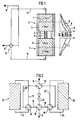
- the device has two chambers 1 and 2, which are connected by an intermediate part 3 designed as a tube, which is provided with an electric heating device 4.
- the two chambers 1 and 2 and the intermediate part 3 are surrounded by thermal insulation 5.
- the two chambers 1 and 2 are filled with a solid, stationary sorbent 6 and 7, respectively, which can be a granulate or in another lumpy form or one of the shaped bodies, e.g. can be a honeycomb shaped body.
- the exhaust gas to be cleaned containing the ozone-depleting and / or climate-effective halogenated compounds, is supplied, for example, in a nitrogen stream via the exhaust line 8, while the cleaned exhaust gas exits into the atmosphere via the outlet line 9.
- the exhaust gas line 8 and the outlet line 9 are connected to a valve device, for example a 4/2-way valve 10, the other two connections of which are connected to the line 11 or 12, which lead into the chamber 1 with the sorbent 6 or into the chamber 2 open with the sorbent 7.
- the chambers 1 and 2 and the intermediate part 3 form a gas space which, in operation (final state), has a temperature profile, as is represented, for example, by curve A in FIG. 1 on the right.
- each chamber 1 or 2 the temperature rises, for example, from room temperature at the point at which the line 11 or 12 is connected to a temperature of, for example, 300 ° C. at the point at which the intermediate part 3 is connected to the heating device 4 is on.
- Tmin in FIG. 1 denotes the temperature which must at least be present so that the ozone-depleting and / or climate-effective halogenated gas to be removed can be decomposed and thus chemisorbed.
- Tmin is approximately 150 ° C.
- the zone with the temperature> Tmin is separated in FIG. 1 from the zone with the temperature ⁇ Tmin by a dashed line.
- the heating device 4 is switched on for heating.
- Unloaded N 2 is supplied via line 8.
- the 4/2-way valve 10 is in the position shown in Figure 1.
- the unloaded N 2 is fed into the chamber 1 until the chamber 2 has a temperature profile approximately according to curve B due to the N 2 heated by the heating device 4.
- the sorbent 7 adjacent to the heating device 4 is thus in the chamber 2 at a temperature> Tmin.
- the N 2 gas emerging from the chamber 2 into the line 12 then has a temperature of, for example, 30 to 40 ° C.
- the 4/2-way valve 10 is switched so that the exhaust gas containing the ozone-depleting and / or climate-effective halogenated compounds is fed in line 8 via line 12 to chamber 2 with the sorbent 7 heated according to curve B.
- the halogenated compounds mentioned are thus chemisorbed in sorbent 7.
- the 4/2-way valve 10 is now switched back to the position shown in Figure 1, so that the exhaust gas flows via line 11 into chamber 1, intermediate piece 3, chamber 2 and then via line 9 into the open until the sorbent 7 in the chamber 2 has the temperature profile according to curve D in FIG. 1.
- This switching of the valve 10 is repeated a number of times, as a result of which the temperature profile A is finally obtained as the final state.
- the switching of the 4/2-way valve 10 in the final state is then carried out until the sorbent 6, 7 in the chambers 1 and 2 is loaded with the decomposition products of said halogenated compounds so that it has to be replaced.
- Both sorption devices S1 and S2 are constructed as shown in Figure 1. I.e. according to FIG. 1, they consist of two chambers 1 and 2, which are connected to a heating device 4 via an intermediate piece 3.
- the exhaust gas line 8 is connected to the valve 13, which is connected via a line 17 to the 4/2-way valve 14, via a line 18 to the 4/2-way valve 15 and via a line 19 to the 4/2-way valve 16 is.
- the 4/2-way valve 14 is on the one hand via a line 11 and on the other hand via a line 12 with the other chamber 1, 2 (compare Figure 1) of the sorption device S1, and via line 20 to the valve 15 to which the outlet line 9 is connected.
- the 4/2-way valve 16 is connected via line 21 on the one hand to one and via line 22 on the other hand to the other chamber 1, 2 (FIG. 1) of the sorption device S2.
- the heaters 4 (FIG. 1) of the two sorption devices S1 and S2 are switched on.
- the exhaust gas is first fed via line 8 to the sorption device S1, specifically according to FIG. 2 of the upper chamber 2 (FIG. 1), so that said halogenated compound is chemisorbed therein, while the chamber 1 of the sorption device S1 is heated.
- the valve 14 By switching the valve 14, the direction of flow in the sorption device S1 is always reversed when the gas emerging from the sorption device S1 has a certain temperature of e.g. Exceeds 30 ° C.
- the cleaned exhaust gas emerging from the sorption device 1 is fed according to FIG. 2 via the valve 15 to the sorption device S2, in which the flow direction can be reversed by switching the valve 16.
- the exhaust gas emerging from the sorption device S2 finally exits via the valve 15 and the outlet line 9.
- the loaded sorbent must be disposed of.
- the sorption device according to FIG. 3 can be used so that this takes place safely and with little effort.
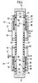
- a lower gas connection part or foot part 23 is provided, on which a lower, barrel-shaped container 24 is placed, and an upper barrel-shaped container 25, to which an upper gas connection part 26 is connected.
- An intermediate part 27 is arranged between the lower barrel 24 and the upper barrel 25.
- the lower gas connection part 23 and the intermediate part 27 have a peripheral wall 28, 30 with a diameter which corresponds to the diameter of the barrels 24, 26.
- borders 38 are provided, which overlap one another, so that the lower barrel 24 onto the lower gas connection part 23 ,
- the intermediate part 27 can be placed on the lower barrel 24 and the upper barrel 25 on the intermediate part 27.
- the border connections 38 are each secured by a tension ring, not shown.
- the lower gas connection part 23 has a valve 39 in the peripheral wall 28, into which the line 11, 12, not shown in FIG. 3, can be inserted with a coupling piece 40.
- the gas connection part 23 is provided with a cover 41, in which a valve 42 is arranged in the center.
- the cover 41 is fastened to the peripheral wall 28 with a border connection 38 with a tension ring, as described above with reference to the other borders 38.
- the lower barrel 24 has a jacket 43 made of heat-insulating material.
- a valve 45 is arranged centrally in its base 44.
- a further valve 46 is located in the removable cover 47.
- a perforated plate or similar gas-permeable wall 48, 49 is provided above the valve 45 and below the valve 46. In between is the solid sorbent 6.
- the upper barrel 25 is designed in the same way. I.e. it has a jacket 50 made of heat-insulating material.
- a valve 52 is arranged in its base 51 and a valve 53 in its removable cover 54 with border 38 '.
- perforated plates 55, 56 are provided, between which the sorbent 7 is located.
- the upper gas connection part 26 is formed by a coupling piece which is inserted into the valve 53 in the cover 54 of the upper barrel 25 and to which the line 11 or 10 (FIG. 1) is connected.
- the intermediate part 27 has a tubular coupling piece 57 which can be inserted at one end into the valve 46 in the cover 47 of the lower barrel 24 and at the other end into the valve 52 in the bottom 51 of the upper barrel 25.
- an electrical heating device 58 which is supplied via electrical lines 59, which are passed through the peripheral wall 37, which is provided on the inside with a jacket 30 made of heat-insulating material, as well as a nitrogen line 61, the function of which is described in the following Connection with Figure 4 is explained in more detail.
- valves 39, 42, 45, 46, 52 and 53 can be designed, for example, as shown in FIG. 4 by means of the valve 46 in the cover 47 of the lower barrel 24 or the valve 52 in the bottom 51 of the upper barrel 25 .
- each valve 46, 52 has a cylindrical valve housing 62, 63, which is welded into the barrel cover 47 or barrel bottom 51.
- the valve housing 62, 63 is provided at its end facing the interior of the associated barrel 24 or 25 with an inner ring 64, 65, on which a sleeve-shaped valve body 66, 67 is displaceably and gas-tightly guided.
- the ring 64, 65 has a groove 68, 69 on its inside, in which a sealing ring 70, 71 is arranged.
- the sleeve-shaped valve body 66, 67 is closed at its end facing the interior of the associated barrel 24, 25 by a base 72, 73, wherein it has gas passage bores 74, 75 on its peripheral wall in front of the base 72, 73.
- the tube 57 which is in each case inserted into the open end of the sleeve-shaped valve body 66, 67, connects the valve bodies 66, 67 to one another and is supported on an inner ring 76, 77 on the valve body 66, 67, which is on the bottom 72, 73 facing away from the gas passage bores 74, 75 is arranged.
- valves 46, 52 which are shown in the open position in FIG. 4, are fault-loaded in the closed position.
- a valve spring designed as a compression spring 79, 80 is provided, which is supported on the one hand on the inner ring 64, 65 on the valve housing 62, 63 and on the other hand on the valve body 66, 67.
- the base 72, 73 moves at the level of the rings 64, 65, as a result of which the gas passage bores 74, 75 are closed.
- valve bodies 66, 67 are fixed in the closed position of the valves 46, 52, there are annular stops 83, 84 on the inside of the valve housing 62, 63 are provided, on which the outer ring flanges 81, 82 come to rest in the closed position.
- annular stops 83, 84 on the inside of the valve housing 62, 63 are provided, on which the outer ring flanges 81, 82 come to rest in the closed position.
- grooves 85 to 88 are provided on both ends of the tube, in which sealing rings 89 to 92 are provided.
- the sealing rings 70, 71 and 89 to 92 are exposed to the high temperatures of the exhaust gas heated by the heating device 58. This can impair their sealing function.
- nitrogen is fed into the chamber 93 between the tube 57 and the peripheral wall 37 or the jacket 60 via the line 61 (FIG. 3) at a pressure which is higher than the pressure of the Exhaust gas in the pipe 57.
- a tubular coupling piece 94 is also provided between the valve 42 in the lower gas closing part 23 and the valve 45 in the bottom 44 of the lower barrel 24.
- the coupling pieces 26, 40 have tubular sections which are inserted into the open ends of the sleeve-shaped valve bodies (not shown) of the valves 53 and 39.
- thermocouple or similar temperature measuring device 95 or 96 is provided in the sorbent 6 or 7 adjacent to the intermediate part 27. Furthermore, a thermocouple or similar temperature measuring device 97 or 98 is provided in the lower or upper gas connection part 23 or 26 (FIG. 3).
- Seals 70, 71 and 89 to 92 can thus be dispensed with entirely.
- the N 2 overpressure in chamber 92 namely forms a gas seal which prevents exhaust gas from escaping from tube 57 or valves 46, 51.
Landscapes
- Chemical & Material Sciences (AREA)
- Engineering & Computer Science (AREA)
- Analytical Chemistry (AREA)
- General Chemical & Material Sciences (AREA)
- Oil, Petroleum & Natural Gas (AREA)
- Chemical Kinetics & Catalysis (AREA)
- Health & Medical Sciences (AREA)
- Biomedical Technology (AREA)
- Environmental & Geological Engineering (AREA)
- Treating Waste Gases (AREA)
- Detergent Compositions (AREA)
- Separation Of Gases By Adsorption (AREA)
Abstract
Description
- Die Erfindung bezieht sich auf eine Vorrichtung und ein Verfahren zur Reinigung von Gasen, die ozonabbauende und/oder klimawirksame halogenierte Verbindungen enthalten, gemäß dem Oberbegrif des Anspruchs 1 bzw. 5.
- In der Halbleiterindustrie werden zum Trockenätzen große Mengen von perfluorierten Verbindungen verwendet, die auch als PFC (Perfluorinated Compounds) bezeichnet werden. Dazu gehören insbesondere Tetrafluorkohlenstoff (CF4), Trifluormethan (CHF3), Hexafluorethan (C2F6) sowie Schwefelhexafluorid (SF6) und Stickstofftrifluorid (NF3). Aus diesen Verbindungen wird beispielsweise durch elektrische Entladung Fluor gebildet, mit dem das Halbleitersubstrat, beispielsweise ein Silizium-Wafer, geäzt wird.
- Perfluorierte Verbindungen sind extrem reaktionsträge. Sie werden daher von den Abgasreinigungsanlagen, die in der Halbleiterindustrie verwendet werden, nicht erfaßt und damit an die Atmosphäre abgegeben. Perfluorierte Verbindungen zeichnen sich jedoch durch hohe Klimawirksamkeit, das sogenannte GWP (Greenhouse Warming Potential) aus. Dies gilt insbesondere für Schwefelhexafluorid, das ein extrem hohes GWP besitzt. Darüberhinaus sind einige dieser Verbindung sehr toxisch, beispielsweise Stickstofftrifluorid.
- Das Problem der Reaktionsträgheit stellt sich nicht nur bei der Abgasreinigung perfluorierter Verbindungen, sondern auch bei anderen halogenierten Verbindungen, insbesondere halogenierten Kohlenwasserstoffen, wie Chlorkohlenwasserstoff (CKW), Chlorfluorkohlenwasserstoff (FCKW), Bromfluorkohlenwasserstoff usw.. Auch diese Stoffe werden daher in großen Mengen an die Atmosphäre abgegeben. Sie sind maßgeblich am Abbau der Ozonschicht in der Stratosphäre beteiligt, besitzen also ein hohes sogenanntes ODP (Ozone Depletion Potential).
- Aus der DE-A-44 04 329 geht eine Vorrichtung und ein Verfahren zur Entfernung ozonabbauender und/oder klimawirksamer halogenierter Verbindungen nach dem Oberbegriff des Anspruchs 1 bzw. 5 hervor, bei dem die halogenierte Verbindung in einem Trägergas-Strom durch ein erwärmtes eisenoxid- oder eisenoxyhydroxidhaltiges Phyllosilikatsorbens geleitet wird. So wird z.B. mit einem auf etwa 300°C erwärmten Bentonit-Festbettreaktor und mit Stickstoff als Trägergas eine quantitative Absorption von Tetrafluorkohlenstoff erhalten. Da das Sorbens eine geringe Wärmeleitfähigkeit besitzt, müßte das Festbett bei einem hohen Gasdurchsatz im industriellen Einsatz mit einem sehr hohen Energieverbrauch geheizt werden. Zwar ist daran zu denken, dem Festbett einen Wärmeaustauscher vorzuschalten, um auch bei einem hohen Gasdurchsatz die notwendige Temperatur von ca. 300 °C im Sorbens aufrechtzuerhalten. Bei Trockenätzprozessen der Halbleitertechnik weist das Abgas jedoch einen hohen Fluorgehalt und damit eine extrem hohe Korrosivität auf. Ein metallischer Wärmetauscher ist daher nicht einsetzbar.
- Zum Entfernen flüchtiger organischer Verbindungen, sogenannter VOC (Volatile Organic Compounds), aus der Abluft beispielsweise von Lackierstraßen, wird die thermische regenerative Abluftreinigung angewandt. Dabei sind wenigstens zwei mit Wärmespeichermaterial versehene Türme über eine Brennkammer verbunden. Der in Strömungsrichtung vor der Brennkammer angeordnete Turm, der vorher auf eine hohe Temperatur gebracht worden ist, heizt die Abluft auf, so daß durch den Brenner nur noch eine geringe Energiemenge zugeführt zu werden braucht. Mit der Zeit sinkt die Temperatur im vorgeschalteten Turm, während sich der nachgeschaltete Turm durch die Verbrennungsgase aufheizt, die aus den vom Brenner verbrannten VOC bestehen. Wenn die aus dem nachgeschalteten Turm austretende gereinigte Abluft eine bestimmte Temperatur erreicht hat, d.h. der nachgeschaltete Turm durch die Verbrennungsgase genügend aufgeheizt ist, wird die Strömungsrichtung des Abgases umgekehrt. Dieses Verfahren wird daher auch als "Thermalswing"-Verfahren bezeichnet.
- Aufgabe der Erfindung ist es, eine wirksame Vorrichtung zur Beseitigung von ozonabbauenden und/oder klimawirksamen halogenierten Verbindungen aus Abgasen für den industriellen Einsatz bereitzustellen.
- Dies wird erfindungsgemäß mit der im Anspruch 1 angegebenen Vorrichtung erreicht. In den Unteransprüchen sind vorteilhafte Ausgestaltungen der erfindungsgemäßen Vorrichtung wiedergegeben.
- Bei der erfindungsgemäßen Vorrichtung sind die beiden Kammern der Sorptionseinrichtung mit einem festen stationären Sorbens für ozonabbauende bzw. klimawirksame halogenierte Verbindungen gefüllt. Das Sorbens führt zur Zersetzung der ozonabbauenden bzw. klimawirksamen halogenierten Verbindung. Zugleich bindet es die gebildeten Zersetzungsprodukte. Im Ergebnis werden die ozonabbauenden bzw. klimawirksamen halogenierten Verbindungen also chemisorbiert. Da die ozonabbauenden bzw. klimawirksamen halogenierten Verbindungen sehr reaktionsträg sind, muß das Sorbens allerdings auf eine hohe Temperatur aufgeheizt werden.
- Wenn die erfindungsgemäße Vorrichtung in Betrieb genommen wird, läßt man zunächst ein unbelastetes Trägergas, also ein Inertgas, wie Stickstoff, bei eingeschalteter Heizeinrichtung durch die Sorptionseinrichtung strömen. Dadurch heizt sich das Sorbens auf, das in der Kammer enthalten ist, welche in Strömungsrichtung der Heizeinrichtung nachgeschaltet ist.
- Wenn das aus dieser Kammer austretende Trägergas eine bestimmte Temperatur überschritten hat, also das Sorbens die für die Zersetzung der ozonabbauenden bzw. klimawirksamen halogenierten Verbindungen erforderliche Temperatur erreicht hat, kann unter Umkehr der Strömungsrichtung dieser Kammer nun das zu reinigende Abgas zugeführt werden.
- Da die halogenierten Verbindungen in dieser Kammer restlos aus dem Abgas entfernt werden, wird die nachgeschaltete Heizeinrichtung keinen korrosiven Verbindungen ausgesetzt.
- Mit der Zeit kühlt sich Sorbens in der der Heizeinrichtung vorgeschalteten Kammer ab, während der anderen Kammer ständig von der Heizeinrichtung aufgeheiztes gereinigtes Abgas zugeführt wird, so daß sich das Sorbens in der der Heizeinrichtung nachgeschalteten Kammer erwärmt. Sobald das Sorbens in der der Heizeinrichtung nachgeschalteten Kammer seinerseits die für die Zersetzung der ozonabbauenden bzw. klimawirksamen halogenierten Verbindungen notwendige Temperatur erreicht hat, wird die Strömungsrichtung des Abgases umgekehrt usw..
- D.h., das Abgas wird abwechselnd jeweils einer der beiden Kammern der Sorptionseinrichtung zugeführt, während die andere Kammer den Auslaß für das gereinigte Gas in die Atmosphäre aufweist.
- Die erfindungsgemäße Vorrichtung ist damit sehr schnell, beispielsweise bereits nach einer Stunde betriebsbereit. Die dann erfolgende abwechselnde Zufuhr des Abgases kann in Intervallen von beispielsweise 5 - 30 Minuten erfolgen. Nach wenigen Stunden haben beide Kammern den optimalen Endzustand erreicht, bei dem mit einer hohen Raumgeschwindigkeit von beispielsweise 1000 h-1 und mehr eine quantitative Beseitung von ozonabbauenden bzw. klimawirksamen halogenierten Verbindungen aus Abgasen mit minimaler Energiezufuhr erreichbar ist.
- Wenn das System den Endzustand erreicht hat, braucht die Heizeinrichtung im wesentlichen nur noch die Wärme zu liefern, die die Vorrichtung abstrahlt. Bei einem Abgas-, d.h. einem Stickstoff-Durchsatz von beispielsweise 100 l/min. und einer Temperatur des Sorbens von ca. 300°C beträgt die Heizleistung der Heizeinrichtung beispielsweise lediglich etwa 150 Watt.
- Zu den ozonabbauenden und/oder klimawirksamen halogenierten Verbindungen, die mit der erfindungsgemäßen Vorrichtung aus einem Gasstrom, insbesondere einem Inertgasstrom, wie einem Stickstoffstrom, entfernt werden können, gehören insbesondere Fluorkohlenwasserstoffe (FKW), Chlorkohlenwasserstoffe (CKW), Chlorfluorkohlenwasserstoffe (FCKW), Bromfluorkohlenwasserstoffe, Bromchlorfluorkohlenwasserstoffe sowie teilhalogenierte Fluorkohlenwasserstoffe und Chlorfluorkohlenwasserstoffe, die 1 bis 4 Kohlenstoffatome besitzen, insbesondere Trichlorfluormethan, Dichlordifluormethan, Bromchlordifluormethan, Dibromdifluormethan, Chlortrifluormethan, Bromtrifluormethan, Tetrafluormethan, Dichlorfluormethan, Chlordifluormethan, Trifluormethan (Fluoroform), Difluormethan (Methylenfluorid), 1,1,2,2-Tetrachlordifluorethan, 1,1,2-Trichlortrifluorethan, 1,2-Dichlortetrafluorethan, 1,2-Dibromtetrafluorethan, Chlorpentafluorethan, Hexafluorethan, 1,2-Dibrom-1,1-difluorethan, 2-Chlor-1,1,1-trifluorethan, 1-Chlor-1,1-difluorethan, 1,1,1-Trifluorethan, 1,1-Difluorethan, Octafluorpropan, Octafluorcyclobutan, Decafluorbutan, 1,1-Dichlordifluorethylen, Chlortrifluorethylen (Trifluorvinylchlorid), 1-Chlor-2,2-difluorethylen, 1,1-Difluorethylen (Vinylidenfluorid).
- Die erfindungsgemäße Vorrichtung ist aber nicht nur zur Entsorgung FCKW, FKW und CKW geeignet, sondern allgemein für Halogenkohlenwasserstoffe anwendbar, also z.B. auch für Halone, Tetrachlorkohlenstoff, Methylchloroform oder teilhalogeniert Halone.
- Ein wichtiges Einsatzgebiet stellt für die erfindungsgemäße Vorrichtung die Reinigung von Abgasen dar, die beim Trockenätzen mit perfluorierten Verbindungen (PFC) in der Halbleiterindustrie anfallen. Die PFC's werden dabei nicht nur zum Ätzen der Halbleiterbauelemente, also z.B. von Siliciumwafer eingesetzt, sondern dienen zugleich als Reinigungsgas für die Kammern zur Herstellung der Halbleiterelemente.
- Neben Tetrafluormethan, Trifluormethan und Hexafluorethan werden dabei als PFCs vor allem auch das sehr toxische Stickstofftrifluorid und das ein besonders hohes GWP aufweisende Schwefelhexafluorid verwendet.
- Die halogenierte Verbindung wird der Sorptionseinrichtung in einem inerten Trägergas zugeführt, z.B. Stickstoff oder ein Edelgas.
- Der Gehalt der halogenierten Verbindung im Abgas bzw. Stickstoffträgergas kann 1 vol.-% und mehr betragen, z.B. 1 - 20 vol.-%.
- Das feste stationäre Sorbens enthält vorzugweise Eisenoxid, Eisenoxyhydroxid, ein Eisenhdroxysalz und/oder Eisenoxyhydroxysalz. Dieses Sorbens wird im einzelnen in der DE-A-44 04 329 beschrieben. Das Eisenoxyhydroxid kann dabei Goethit und das Eisenoxyd Maghemit, Magnetit, Ferrihydrit oder Hämatit sein. Das Sorbens weist weiterhin vorzugsweise ein Phylosilikat mit einem Anteil von mindestens 10, vorzugsweise mindestens 50 Gew.-% auf. Das Phyllosilikat kann ein Mineral der Montmorin-Gruppe, Talk und/oder ein Mineral der Glimmergruppe sein. Als Minerale der Montmorin-Gruppe können insbesondere Bentonite und damit eng verwandte Tonmaterialien, wie Montmorillonit, Nontronit, Saponit oder Vermicullit eingesetzt werden. Als Mineral der Glimmergruppe sind beispielsweise Muskovit, Biotit, Illit, Phlogopit, Lepidolith, Margarit, Paragonit und Chloritoid zu nennen. Ebenso können Kaoline oder Chamosit sowie Serpentin-Mineralien zum Einsatz kommen.
- Damit die ozonabbauende bzw. klimawirksame halogenierte Verbindung zersetzt wird, muß das Sorbens in der Kammer, die Strömungsrichtung der Heizeinrichtung vorgeordnet ist, auf die erforderliche Zersetzungstemperatur erwärmt sein, die im allgemeinen zwischen 150 und 450 °C liegt.
- Dabei ist es nicht erforderlich, daß das gesamte Sorbens in der der Heizeinrichtung vorgeschalteten Kammer diese hohe Zersetzungstemperatur besitzt. Vielmehr reicht es aus, wenn nur die der Heizeinrichtung benachbarte Zone des Sorbens auf die Zersetzungstemperatur der ozonabbauenden und/oder klimawirksamen halogenierten Verbindungen erwärmt ist, während der restliche Teil des Sorbens eine Zone mit einer niedrigeren Temperatur bildet.
- In dieser Zone niedriger Temperatur werden dann die reaktionsfreudigeren Verbindungen in dem Abgas gebunden, die bei dem jeweiligen industriellen Prozeß anfallen. So enthält, z.B. das Abgas, das beim Trockenätzen in der Halbleitindustrie mit PFC anfällt, beispielsweise Fluorgas (F2) Siliziumtetrafluorid, Fluorphosgen (COF2) und dergleichen reaktionsfreudige Gase, die bereits bei Raumtemperatur absorbiert werden. Dabei kann das Sorbens, das für die Zone niedriger Temperatur verwendet wird, das gleiche oder ein anderes Sorbens sein als das Sorbens, das zur Chemisorption der ozonabbauenden und/oder klimawirksamen halogenierten Verbindungen in der heißen Zone eingesetzt wird.
- Die erfindungsgemäße Vorrichtung kann auch zur Entsorgung von ozonabbauenden und/oder klimawirksamen halogenierten Verbindungen eingesetzt werden. Die halogenierten Verbindungen werden dazu in einem Trägergas, insbesondere Stickstoff, in Dampfform der erfindungsgemäßen Vorrichtung zugeführt. Dabei ist zu bedenken, daß riesige Mengen dieser Verbindungen entsorgt werden müssen.
- Das verbrauchte Sorbens soll gefahrlos und ohne großen Aufwand entsorgt werden können.
- Dazu kann erfindungsgemäß vorzugsweise auf die Sorptionskolonne nach der DE-A-41 02 969 zurückgegriffen werden. Diese kann aus zwei aufeinanderstapelbaren Fässern oder dergleichen Behältern gebildet sein, von denen jeder ein Ventil im Deckel und ein Ventil im Boden aufweist. Das untere Faß ist auf ein unteres Gasanschlußteil stellbar, und an das obere Faß ein oberes Gasanschlußteil anschließbar. Das untere und das obere Gasanschlußteil weisen dazu jeweils ein Kupplungsstück auf, das mit dem Ventil im Boden des unteren Fasses bzw. mit dem Ventil im Deckel des oberen Fasses zusammensteckbar ausgebildet ist. Ebenso ist das Ventil im Deckel des unteren Behälters mit dem Ventil im Boden des darauf gestapelten Behälters bei der bekannten Sorptionskolonne zusammensteckbar ausgebildet. Wenn alle Ventile zusammengesteckt sind, wird ein sich vom unteren Gasanschlußteil zum oberen Gasanschlußteil kommunizierender Gasraum gebildet.
- Um die erfindungsgemäße Vorrichtung zu bilden, braucht die bekannte Sorptionskolonne im wesentlichen nur zum Zusammenstecken des Ventils im Deckel des unteren Behälters mit dem Ventil im Boden des oberen Behälters mit einem Zwischenteil versehen zu werden, das die Heizeinrichtung aufweist. Ferner sind die Behälter vorzugsweise mit einer Wärmeisolierung versehen.
- Nachstehend ist die Erfindung anhand der Zeichnung beispielsweise näher erläutert. Darin zeigen:
- Fig. 1
- schematisch eine Abgasreinigungsvorrichtung mit einer Sorptionseinrichtung mit zwei Kammern sowie ein Diagramm, das das Betriebstemperaturprofil in der Sorptionseinrichtung darstellt;
- Fig. 2
- schematisch zwei in Serie geschaltete Sorptionseinrichtungen mit jeweils zwei Kammern;
- Fig. 3
- einen Längsschnitt durch eine Ausführungsform einer Sorptionseinrichtung nach Figur 1 oder Figur 2;
- Fig. 4
- in gegenüber Figur 3 vergrößerter Wiedergabe einen Längsschnitt durch die Sorptionseinrichtung im Bereich des Zwischenteils.
- Gemäß Figur 1 weist die Vorrichtung zwei Kammern 1 und 2 auf, die durch ein als Rohr ausgebildetes Zwischenteil 3 verbunden sind, das mit einer elektrischen Heizeinrichtung 4 versehen ist. Die beiden Kammern 1 und 2 und das Zwischenteil 3 sind von einer Wärmeisolation 5 umgeben. Die beiden Kammern 1 und 2 sind mit einem festen, stationären Sorbens 6 bzw. 7 gefüllt, das ein Granulat sein oder in anderer stückiger Form vorliegen oder ein vom Formkörper, z.B. ein honigwabenförmiger Formkörper sein kann.
- Das zu reinigende, die ozonabbauende und/oder klimawirksame halogenierte Verbindungen enthaltende Abgas, wird z.B. in einem Stickstoffstrom über die Abgasleitung 8 zugeführt, während das gereinigte Abgas über die Auslaßleitung 9 in die Atmosphäre austritt. Die Abgasleitung 8 und die Auslaßleitung 9 sind an eine Ventileinrichtung, beispielsweise ein 4/2-Wegeventil 10 angeschlossen, dessen beide andere Anschlüsse mit der Leitung 11 bzw. 12 verbunden sind, die in die Kammer 1 mit dem Sorbens 6 bzw. in die Kammer 2 mit dem Sorbens 7 münden.
- Die Kammern 1 und 2 und das Zwischenteil 3 bilden einen Gasraum, der im Betrieb (Endzustand) einen Temperaturverlauf aufweist, wie er beispielsweise durch die Kurve A in Figur 1 rechts wiedergegeben ist.
- D.h. in jeder Kammer 1 bzw. 2 steigt die Temperatur beispielsweise von Raumtemperatur an der Stelle, an der die Leitung 11 bzw. 12 angeschlossen ist, auf eine Temperatur von beispielsweise 300 °C an der Stelle, an der das Zwischenteil 3 mit der Heizeinrichtung 4 angeschlossen ist, an.
- Mit Tmin ist in die Figur 1 die Temperatur bezeichnet, die mindestens vorliegen muß, damit das zu entfernende ozonabbauende und/oder klimawirksame halogenierte Gas zersetzt und damit chemisorbiert werden kann. Tmin liegt beispielsweise bei ca. 150 °C. Die Zone mit der Temperatur > Tmin ist in Figur 1 von der Zone mit der Temperatur < Tmin durch eine gestrichelte Linie getrennt.
- Zum Aufheizen wird die Heizeinrichtung 4 eingeschaltet. Dabei wird unbelastetes N2 über die Leitung 8 zugeführt. Das 4/2-Wegeventil 10 befindet sich in der in Figur 1 dargestellten Stellung. Das unbelastete N2 wird der Kammer 1 solange zugeführt bis die Kammer 2 durch das mit der Heizeinrichtung 4 aufgeheizte N2 einen Temperaturverlauf etwa gemäß der Kurve B aufweist. Damit befindet sich das der Heizeinrichtung 4 benachbarte Sorbens 7 in der Kammer 2 auf einer Temperatur > Tmin. Das aus der Kammer 2 in die Leitung 12 austretende N2-Gas weist dann eine Temperatur von z.B. 30 bis 40°C auf. Jetzt wird das 4/2-Wegeventil 10 umgeschaltet, so daß das die ozonabbauenden und/oder klimawirksamen halogenierten Verbindungen enthaltende Abgas in der Leitung 8 über die Leitung 12 der Kammer 2 mit dem gemäß der Kurve B aufgeheizten Sorbens 7 zugeführt wird. Die erwähnten halogenierten Verbindungen werden damit im Sorbens 7 chemisorbiert.
- Das gereinigte, durch das Sorbens 7 aufgeheizte Abgas strömt, nachdem es im Zwischenteil mit der Heizung 4 noch weiter aufgeheizt worden ist, in die Kammer 1 mit dem Sorbens 6, bis die Kammer 1 den Temperaturverlauf nach der Kurve C in Figur 1 annimmt.
- Das 4/2-Wegeventil 10 wird nun wieder in die in Figur 1 dargestellte Stellung umgeschaltet, so daß das Abgas über die Leitung 11 in die Kammer 1, das Zwischenstück 3, die Kammer 2 und dann über die Leitung 9 ins Freie strömt, bis das Sorbens 7 in der Kammer 2 den Temperaturverlauf gemäß der Kurve D in Figur 1 aufweist. Dieses Umschalten des Ventils 10 wird mehrmals wiederholt, wodurch schließlich der Temperaturverlauf A als Endzustand erhalten wird. Das Umschalten des 4/2-Wegeventils 10 im Endzustand wird dann solange durchgeführt, bis das Sorbens 6, 7 in den Kammern 1 und 2 mit den Zersetzungsprodukten der besagten halogenierten Verbindungen so beladen ist, daß es ausgetauscht werden muß.
- Um die Abgasreinigung beim Austausch des Sorbens 6, 7 nicht unterbrechen zu müssen, ist es zweckmäßig gemäß Figur 2 zwei Sorptionseinrichtungen S1 und S2 zu verwenden.
- Beide Sorptionseinrichtungen S1 und S2 sind dabei so aufgebaut, wie in Figur 1 dargestellt. D.h. sie bestehen gemäß Figur 1 aus zwei Kammern 1 und 2, die über ein Zwischenstück 3 mit einer Heizeinrichtung 4 verbunden sind.
- Dabei sind in Figur 2 vier Ventileinrichtungen, und zwar 4/2-Wegeventile 13, 14, 15 und 16 vorgesehen. Die Abgasleitung 8 ist an das Ventil 13 angeschlossen, das über eine Leitung 17 mit dem 4/2-Wegeventil 14, über eine Leitung 18 mit dem 4/2-Wegeventil 15 und über eine Leitung 19 mit dem 4/2-Wegeventil 16 verbunden ist.
- Das 4/2-Wegeventil 14 ist über eine Leitung 11 einerseits mit der einen und über eine Leitung 12 andererseits mit der anderen Kammer 1, 2 (vergleiche Figur 1) der Sorptionseinrichtung S1 verbunden, und über die Leitung 20 mit dem Ventil 15, an das die Auslaßleitung 9 angeschlossen ist. Das 4/2-Wegeventil 16 ist über die Leitung 21 einerseits mit der einen und über die Leitung 22 andererseits mit der anderen Kammer 1, 2 (Figur 1) der Sorptionseinrichtung S2 verbunden.
- In der in Figur 2 dargestellten Betriebsstellung sind die Heizungen 4 (Figur 1) der beiden Sorptionseinrichtung S1 und S2 eingeschaltet. Das Abgas wird über die Leitung 8 zunächst der Sorptionseinrichtung S1 zugeführt, und zwar nach Figur 2 der oberen Kammer 2 (Figur 1), so daß in dieser die besagte halogenierte Verbindung chemisorbiert wird, während die Kammer 1 der Sorptionseinrichtung S1 aufgeheizt wird. Durch Umschalten des Ventils 14 wird die Strömungsrichtung in der Sorptionseinrichtung S1 immer dann umgekehrt, wenn das aus der Sorptionseinrichtung S1 austretende Gas eine bestimmte Temperatur von z.B. 30 °C überschreitet.
- Das aus der Sorptionseinrichtung 1 austretende gereinigte Abgas wird gemäß Figur 2 über das Ventil 15 der Sorptionseinrichtung S2 zugeführt, in der ihrerseits durch Umschalten des Ventils 16 die Strömungsrichtung umgekehrt werden kann. Das aus der Sorptionseinrichtung S2 austretende Abgas tritt schließlich über das Ventil 15 und der Auslaßleitung 9 ins Freie.
- Mit der Sorptionseinrichtung S2 steht also stets eine unbeladene, betriebsbereite Sorptionseinrichtung zur Verfügung. Zugleich werden durch die Sorptionseinrichtung S2 die Abgasvolumina gereinigt, die in der kälteren Zone < Tmin des Sorbens 6, 7 vorliegen, wenn die Strömungsrichtung in der Sorptionseinrichtung S1 durch Umschalten des 4/2-Wegeventil 14 geändert wird.
- Wenn das Sorbens 6, 7 in der betreffenden Sorptionseinrichtung S1, S2 beladen ist, wird es durch frisches Sorbens ersetzt. Die Abgasreinigung kann dann vorübergehend nur mit der anderen, unbeladenen Sorptionseinrichtung S2 bzw. S1 durchgeführt werden. Freilich ist es auch möglich, drei Sorptionseinrichtungen in Serie so miteinander zu verbinden, wie in Figur 2 dargestellt.
- Das beladene Sorbens muß entsorgt werden. Damit dies gefahrlos und ohne großen Aufwand geschieht, kann die Sorptionseinrichtung nach Figur 3 verwendet werden.
- Danach ist ein unteres Gasanschlußteil oder Fußteil 23 vorgesehen, auf dem ein unterer, faßförmiger Behälter 24 abgestellt ist, sowie ein oberer faßförmiger Behälter 25, an den ein oberes Gasanschlußteil 26 angeschlossen ist.
- Zwischen dem unteren Faß 24 und dem oberen Faß 25 ist ein Zwischenteil 27 angeordnet.
- Das untere Gasanschlußteil 23 und das Zwischenteil 27 weisen eine Umfangswand 28, 30 mit einem Durchmesser auf, der dem Durchmesser der Fässer 24, 26 entspricht.
- Am oberen Rand der Umfangswand 28 des unteren Gasanschlußteils 23 sowie an den unteren und oberen Rändern der Fässer 24, 25 und der Umfangswand 30 des Zwischenteils 27 sind jeweils Bordüren 38 vorgesehen, die einander übergreifen, so daß das untere Faß 24 auf das untere Gasanschlußteil 23, das Zwischenteil 27 auf das untere Faß 24 und das obere Faß 25 auf das Zwischenteil 27 gestellt werden können. Die Bordür-Verbindungen 38 werden jeweils durch einen nicht dargestellten Spannring gesichert.
- Das untere Gasanschlußteil 23 weist ein Ventil 39 in der Umfangswand 28 auf, in das die in Figur 3 nicht dargestellte Leitung 11, 12 mit einem Kupplungsstück 40 steckbar ist.
- Das Gasanschlußteil 23 ist mit einem Deckel 41 versehen, in dem mittig ein Ventil 42 angeordnet ist. Der Deckel 41 ist an der Umfangswand 28 mit einer Bordür-Verbindung 38 mit einem Spannring befestigt, wie vorstehend anhand der anderen Bordüren 38 geschildert.
- Das untere Faß 24 weist einen Mantel 43 aus wärmeisolierendem Material auf. In seinem Boden 44 ist ein Ventil 45 mittig angeordnet. Ein weiteres Ventil 46 befindet sich im abnehmbaren Deckel 47. Oberhalb des Ventils 45 sowie unterhalb des Ventils 46 ist jeweils ein Lochblech oder dergleichen gasdurchlässige Wand 48, 49 vorgesehen. Dazwischen befindet sich das feste Sorbens 6.
- Das obere Faß 25 ist in gleicher Weise ausgebildet. D.h. es weist einen Mantel 50 aus wärmeisolierendem Material auf. In seinem Boden 51 ist ein Ventil 52 angeordnet, und in seinem abnehmbaren Deckel 54 mit Bordüre 38' ein Ventil 53. Desgleichen sind Lochbleche 55, 56 vorgesehen, zwischen denen sich das Sorbens 7 befindet.
- Das obere Gasanschlußteil 26 wird durch ein Kupplungsstück gebildet, das in das Ventil 53 im Deckel 54 des oberen Fasses 25 gesteckt ist und an das die Leitung 11 bzw. 10 (Figur 1) angeschlossen ist.
- Das Zwischenteil 27 weist ein rohrförmiges Kupplungsstück 57 auf, das mit einem Ende in das Ventil 46 im Deckel 47 des unteren Fasses 24 und mit dem anderen Ende in das Ventil 52 im Boden 51 des oberen Fasses 25 steckbar ist.
- In dem Rohr 57 befindet sich eine elektrische Heizeinrichtung 58, die über elektrische Leitungen 59 versorgt wird, die durch die Umfangswand 37, die innen mit einem Mantel 30 aus wärmeisolierendem Material versehen ist, hindurchgeführt sind, ebenso wie eine Stickstoffleitung 61, deren Funktion nachstehend im Zusammenhang mit der Figur 4 näher erläutert wird.
- Die Ventile 39, 42, 45, 46, 52 und 53 können beispielsweise so ausgebildet sein, wie dies in der Figur 4 anhand des Ventils 46 im Deckel 47 des unteren Fasses 24 bzw. des Ventils 52 im Boden 51 des oberen Fasses 25 dargestellt ist.
- Danach weist jedes Ventil 46, 52 ein zylindrisches Ventilgehäuse 62, 63 auf, das in den Faßdeckel 47 bzw. Faßboden 51 eingeschweißt ist. Das Ventilgehäuse 62, 63 ist an seinem dem Inneren des zugehörigen Fasses 24 bzw. 25 zugewandten Ende mit einem Innenring 64, 65 versehen, an dem ein hülsenförmiger Ventilkörper 66, 67 verschieblich und gasdicht geführt ist. Dazu weist der Ring 64, 65 eine Nut 68, 69 an seiner Innenseite auf, in der ein Dichtring 70, 71 angeordnet ist. Der hülsenförmige Ventilkörper 66, 67 ist an seinem dem Inneren des zugehörigen Fasses 24, 25 zugewandten Ende durch einen Boden 72, 73 verschlossen, wobei er an seiner Umfangswand vor dem Boden 72, 73 Gasdurchtrittsbohrungen 74, 75 aufweist.
- Das Rohr 57, das jeweils in das offene Ende des hülsenförmigen Ventilkörpers 66, 67 gesteckt ist, verbindet die Ventilkörper 66, 67 miteinander und stützt sich an einem Innenring 76, 77 am Ventilkörper 66, 67 ab, der auf der von dem Boden 72, 73 abgewandten Seite der Gasdurchtrittsbohrungen 74, 75 angeordnet ist.
- Die Ventile 46, 52, die in Figur 4 in der geöffneten Stellung gezeigt sind, sind in Schließstellung fehlerbelastet. Dazu ist eine als Druckfeder 79, 80 ausgebildete Ventilfeder vorgesehen, die sich einerseits an dem Innenring 64, 65 am Ventilgehäuse 62, 63 und andererseits am Ventilkörper 66, 67 abstützt. Wenn sich die Ventilkörper 66, 67 in die Schließstellung bewegen, bewegt sich der Boden 72, 73 in Höhe der Ringe 64, 65 wodurch die Gasdurchtrittsbohrungen 74, 75 geschlossen werden. Damit die Ventilkörper 66, 67 in der Schließstellung der Ventile 46, 52 fixiert sind, sind ringförmige Anschläge 83, 84 an der Innenseite des Ventilgehäuses 62, 63 vorgesehen, an denen die Außenringflansche 81, 82 in Schließstellung zur Anlage gelangen. Um das rohrförmige Zwischenteil 27 gegenüber den Ventilkörpern 66, 67 abzudichten, sind an beiden Enden des Rohres 57 Nuten 85 bis 88 vorgesehen, in denen Dichtringe 89 bis 92 vorgesehen sind.
- Die Dichtringe 70, 71 sowie 89 bis 92 sind den hohen Temperaturen des durch die Heizeinrichtung 58 aufgeheizten Abgases ausgesetzt. Dadurch kann ihre Dichtfunktion beeinträchtigt werden. Um einen Austritt von Abgas im Zwischenteil 27 zu vermeiden, wird in die Kammer 93 zwischen dem Rohr 57 und der Umfangswand 37 bzw. dem Mantel 60 über die Leitung 61 (Figur 3) Stickstoff mit einem Druck zugeführt, der höher ist als der Druck des Abgases in dem Rohr 57.
- Zwischen dem Ventil 42 in dem unteren Gasabschlußteil 23 und dem Ventil 45 im Boden 44 des unteren Fasses 24 ist ebenfalls ein rohrförmiges Kupplungsstück 94 vorgesehen. Desgleichen weisen die Kupplungsstücke 26, 40 rohrförmige Abschnitte auf, die in die offenen Enden der nicht dargestellten hülsenförmigen Ventilkörper der Ventile 53 und 39 gesteckt sind.
- Je ein Thermoelement oder dergleichen Temperaturmeßeinrichtung 95 bzw. 96 ist im Sorbens 6 bzw. 7 benachbart zum Zwischenteil 27 vorgesehen. Ferner ist je ein Thermoelement oder dergleichen Temperaturmeßeinrichtung 97 bzw. 98 im unteren bzw. oberen Gasanschlußteil 23 bzw. 26 vorgesehen (Figur 3).
- Damit kann auf die Dichtungen 70, 71 sowie 89 bis 92 ganz verzichtet werden. Der N2-Überdruck in der Kammer 92 bildet nämlich eine Gasdichtung, die einen Abgas-Austritt aus dem Rohr 57 bzw. der Ventilen 46, 51 verhindert.
Claims (10)
- Vorrichtung zur Reinigung von Abgasen, die ozonabbauende und/oder klimawirksame halogenierte Verbindungen enthalten, mit wenigstens einer Sorptionseinrichtung, die ein festes stationäres Sorbens für die ozonabbauenden und/oder klimawirksamen halogenierten Verbindungen, eine Gaszufuhr für das zu reinigende Abgas und eine Heizeinrichtung aufweist, dadurch gekennzeichnet, daß die Sorptionseinrichtung (S1, S2) zwei Kammern (1, 2) aufweist, die jeweils ein festes stationäres Sorbens (6, 7) für die ozonabbauenden und/oder klimawirksamen halogenierten Verbindungen enthalten und über die Heizeinrichtung (4, 58) miteinander kommunizieren, wobei die beiden Kammern (1, 2) zur Umkehrung der Strömungsrichtung des zu reinigenden Abgases abwechselnd mit der Gaszufuhr (8) verbindbar sind.
- Vorrichtung nach Anspruch 1, dadurch gekennzeichnet, daß zwei Sorptionseinrichtungen (S1, S2) mit jeweils zwei Kammern (1, 2) vorgesehen sind, wobei der Auslaß (11, 12) der ersten Sorptionseinrichtung (S1) mit der Gaszufuhr (21, 22) der zweiten Sorptionseinrichtung (S2) verbindbar ist.
- Vorrichtung nach Anspruch 1 oder 2, dadurch gekennzeichnet, daß die beiden Kammern (1, 2) jeder Sorptionseinrichtung (S1, S2) durch zwei übereinander angeordnete Behälter (24, 25) gebildet sind, von denen jeder ein Ventil (45, 57) im Boden (44, 51) und ein Ventil (46, 53) an der oberen Seite (42, 54) aufweist, wobei ein unteres Gasanschlußteil (23), an das der untere Behälter (24) anschließbar ist, ein Zwischenteil (27) mit einer Heizeinrichtung (58) und ein oberes Gasanschlußteil (26), das an den oberen Behälter (25) anschließbar ist, vorgesehen sind, wobei das Zwischenteil (27) und die beiden Gasanschlußteile (23, 26) Kupplungsstücke (57, 94) aufweisen, das Kupplungsstück (57) des Zwischenteils (27) mit dem Ventil (46) in der oberen Seite (47) des unteren Behälters (24) und mit dem Ventil (52) im Boden (51) des oberen Behälters (25), das Kupplungsstück (94) des unteren Gasanschlußteils (23) mit dem Ventil (45) im Boden (44) des unteren Behälters (24) und das Ventil (53) in der oberen Seite (54) des oberen Behälters (25) mit dem Kupplungsstück des oberen Gasanschlußteils (26) zusammensteckbar ausgebildet sind, und sich alle Ventile (45, 46, 52, 53) der Behälter (24, 25) beim Zusammenstecken mit den Kupplungsstücken (57, 94) unter Bildung eines vom unteren Gasanschlußteil (23) zum oberen Gasanschlußteil (26) kommunizierenden Gasraums öffnen.
- Vorrichtung nach Anspruch 3, dadurch gekennzeichnet, daß das Zwischenteil (27) zumindest in dem Bereich, mit in dem das Kupplungsstück (57) an das Ventil (46) in der Oberseite (47) des unteren Behälters (24) und in das Ventil (52) im Boden (54) des oberen Behälters (25) zugesteckt wird, eine Kammer (93) aufweist, welcher ein Inertgas zugeführt wird.
- Verfahren zur Reinigung von Abgasen, die Ozon abbauende und/oder klimawirksame halogenierte Verbindungen enthalten, mit einer Sorptionseinrichtung, die wenigstens ein festes stationäres Bett für die ozonabbauenden und/oder klimawirksamen halogenierten Verbindungen und eine Heizeinrichtung aufweist, dadurch gekennzeichnet, daß die Sorptionseinrichtung (S1, S2) zwei Kammern (1, 2) aufweist, die jeweils ein festes stationäres Sorbens (6, 7) für die ozonabbauenden und/oder klimawirksamen halogenierten Verbindungen enthalten und über die Heizeinrichtung (4, 58) miteinander kommunizieren, wobei folgende Schritte durchgeführt werden:a) das Sorbens (6, 7) in einer der beiden Kammern (1, 2) wird zumindest teilweise auf eine zur Zersetzung der ozonabbauenden und/oder klimawirksamen halogenierten Verbindungen erforderliche Temperatur erwärmt,b) das zu reinigende Abgas wird bei eingeschalteter Heizeinrichtung der auf diese Temperatur erwärmten einen, ersten Kammer (1, 2) zugeführt, und darin gereinigt,c) das aus der ersten Kammer (1, 2) austretende gereinigte Abgas strömt nach Erwärmung in der Heizeinrichtung (4, 58) in die zweite Kammer (2, 1), bis dessen Sorbens (7, 6) zumindest teilweise die für die Zersetzung der ozonabbauenden und/oder klimawirksamen halogenierten Verbindungen erforderliche Temperatur erreicht hat,d) das zu reinigende Abgas wird der zweiten Kammer (2, 1) zugeführt und dann gereinigt,e) das aus der zweiten Kammer (2, 1) austretende gereinigte Abgas strömt nach Erwärmung in der Heizeinrichtung in die erste Kammer (1, 2), bis dessen Sorbens (6, 7) zumindest teilweise die für die Zersetzung der ozonabbauenden und/oder klimawirksamen halogenierten Verbindungen erforderliche Temperatur erreicht hat,f) die Schritte (b) bis (e) werden wiederholt.
- Verfahren nach Anspruch 5, dadurch gekennzeichnet, daß der Schritt (a) durchgeführt wird, indem bei eingeschalteter Heizeinrichtung (4, 58) der zweiten Kammer (2, 1) ein inertes Trägergas zugeführt wird.
- Verfahren nach Anspruch 5, dadurch gekennzeichnet, daß das zu reinigende Abgas die ozonabbauenden und/oder klimawirksamen halogenierten Verbindungen in einem inerten Trägergas enthält.
- Verfahren nach Anspruch 6 oder 7, dadurch gekennzeichnet, daß das inerte Trägergas Stickstoff ist.
- Verfahren nach Anspruch 5, dadurch gekennzeichnet, daß die für die Zersetzung der ozonabbauenden und/oder klimawirksamen halogenierten Verbindungen erforderliche Temperatur mindestens 150° C beträgt.
- Verfahren nach Anspruch 5, dadurch gekennzeichnet, daß die für die Zersetzung der ozonabbauenden und/oder klimawirksamen halogenierten Verbindungen erforderliche Temperatur 150° C bis 500° C beträgt.
Applications Claiming Priority (2)
| Application Number | Priority Date | Filing Date | Title |
|---|---|---|---|
| DE19532279 | 1995-09-01 | ||
| DE19532279A DE19532279C2 (de) | 1995-09-01 | 1995-09-01 | Vorrichtung zur Reinigung von Gasen, die ozonabbauende und/oder klimawirksame halogenierte Verbindungen enthalten |
Publications (2)
| Publication Number | Publication Date |
|---|---|
| EP0761288A1 true EP0761288A1 (de) | 1997-03-12 |
| EP0761288B1 EP0761288B1 (de) | 2000-08-09 |
Family
ID=7771003
Family Applications (1)
| Application Number | Title | Priority Date | Filing Date |
|---|---|---|---|
| EP96108745A Expired - Lifetime EP0761288B1 (de) | 1995-09-01 | 1996-05-31 | Vorrichtung und Verfahren zur Reinigung von Gasen, die halogenierte Verbindungen enthalten |
Country Status (7)
| Country | Link |
|---|---|
| US (1) | US5762893A (de) |
| EP (1) | EP0761288B1 (de) |
| JP (1) | JPH09103643A (de) |
| KR (1) | KR100417759B1 (de) |
| AT (1) | ATE195264T1 (de) |
| DE (2) | DE19532279C2 (de) |
| TW (1) | TW316238B (de) |
Families Citing this family (16)
| Publication number | Priority date | Publication date | Assignee | Title |
|---|---|---|---|---|
| EP0907402B1 (de) * | 1996-06-26 | 2001-05-23 | Cs Clean Systems Ag | Verfahren zur entfernung ozonabbauender und/oder klimawirksamer fluorierter verbindungen aus einem gasstrom sowie anwendung des verfahrens |
| TW550112B (en) * | 1997-11-14 | 2003-09-01 | Hitachi Ltd | Method for processing perfluorocarbon, and apparatus therefor |
| US8231851B2 (en) | 1997-11-14 | 2012-07-31 | Hitachi, Ltd. | Method for processing perfluorocarbon, and apparatus therefor |
| US6468490B1 (en) * | 2000-06-29 | 2002-10-22 | Applied Materials, Inc. | Abatement of fluorine gas from effluent |
| US6689252B1 (en) | 1999-07-28 | 2004-02-10 | Applied Materials, Inc. | Abatement of hazardous gases in effluent |
| US6391146B1 (en) | 2000-04-11 | 2002-05-21 | Applied Materials, Inc. | Erosion resistant gas energizer |
| US6673323B1 (en) | 2000-03-24 | 2004-01-06 | Applied Materials, Inc. | Treatment of hazardous gases in effluent |
| US6824748B2 (en) * | 2001-06-01 | 2004-11-30 | Applied Materials, Inc. | Heated catalytic treatment of an effluent gas from a substrate fabrication process |
| US7060236B2 (en) * | 2002-10-21 | 2006-06-13 | Yan Tsoung Y | Process for removing volatile organic compounds |
| US7569193B2 (en) | 2003-12-19 | 2009-08-04 | Applied Materials, Inc. | Apparatus and method for controlled combustion of gaseous pollutants |
| US7736599B2 (en) | 2004-11-12 | 2010-06-15 | Applied Materials, Inc. | Reactor design to reduce particle deposition during process abatement |
| CN101300411B (zh) | 2005-10-31 | 2012-10-03 | 应用材料公司 | 制程减降反应器 |
| DE102006018252B4 (de) * | 2006-04-20 | 2009-02-05 | Cs Clean Systems Ag | Sorptionskolonne |
| DE102007049613B4 (de) | 2007-10-17 | 2010-08-12 | Cs Clean Systems Ag | Fahrwerk für Fässer, insbesondere zu Sorptionskolonnen |
| CN108977671B (zh) * | 2018-08-31 | 2024-05-31 | 江西海汇龙洲锂业有限公司 | 一种便于收集滤渣的锂云母生产用除杂装置 |
| CN113332851B (zh) * | 2021-02-24 | 2023-08-29 | 薛援 | 一种移动床干法烟气脱硫方法 |
Citations (5)
| Publication number | Priority date | Publication date | Assignee | Title |
|---|---|---|---|---|
| DE549531C (de) * | 1928-02-14 | 1932-04-28 | Metallgesellschaft Ag | Verfahren zur Ausfuehrung von Adsorptions- und Regenerationsvorgaengen |
| DE4135018A1 (de) * | 1990-11-30 | 1992-06-04 | Otto Oeko Tech | Verfahren und vorrichtung zur stroemungsfuehrung in radialstromreaktoren |
| EP0490632A1 (de) * | 1990-12-13 | 1992-06-17 | The Boc Group, Inc. | Kontinuierliches Verfahren zur Entfernung von Öldampf aus öl- und wasserdampfhaltigen Speisegasen |
| DE4102969C1 (de) * | 1991-02-01 | 1992-10-08 | Cs Halbleiter- Und Solartechnologie Gmbh, 8000 Muenchen, De | |
| EP0599271A1 (de) * | 1992-11-25 | 1994-06-01 | Air Products And Chemicals, Inc. | Verfahren zur Entfernung und Vernichtung von niedrigen Konzentrationen von oxidierbaren organischen Verunreinigungen aus einem Gasstrom |
Family Cites Families (13)
| Publication number | Priority date | Publication date | Assignee | Title |
|---|---|---|---|---|
| US2083732A (en) * | 1932-11-22 | 1937-06-15 | Pittsburgh Res Corp | Adsorbent apparatus |
| US2121733A (en) * | 1935-08-14 | 1938-06-21 | Research Corp | Purifying gases and apparatus therefor |
| BE759295A (fr) * | 1969-12-09 | 1971-04-30 | Allied Chem | Procede de traitement d'anhydride sulfureux avec un gaz reducteur et nouveaux produits ainsi obtenus |
| US3893827A (en) * | 1973-08-15 | 1975-07-08 | Cjb Dev Limited | Selective removal of constituents from fluids |
| US3981698A (en) * | 1973-08-15 | 1976-09-21 | Cjb Development Limited | Process for the removal of carbon dioxide from gases |
| DE3232138C2 (de) * | 1982-08-28 | 1989-05-18 | Rekuperator KG Dr.-Ing. Schack & Co, 4000 Düsseldorf | Verfahren und Vorrichtung zum Reinigen eines Gasstromes in einem Sorptionsfilter |
| US4516988A (en) * | 1983-08-25 | 1985-05-14 | Rekuperator Kg Dr.-Ing. Schack & Co. | Method and apparatus for purifying a gas stream in a sorption filter |
| GB8900506D0 (en) * | 1989-01-10 | 1989-03-08 | Willpower Compressed Air Syst | Compressed gas purifier |
| US5024817A (en) * | 1989-12-18 | 1991-06-18 | The Air Preheater Company, Inc. | Twin bed regenerative incinerator system |
| US5366708A (en) * | 1992-12-28 | 1994-11-22 | Monsanto Eviro-Chem Systems, Inc. | Process for catalytic reaction of gases |
| DE4404329C2 (de) * | 1994-02-11 | 1996-07-11 | Cs Halbleiter Solartech | Entsorgung von Flourchlorkohlenwasserstoffen und Halonen |
| US5425242A (en) * | 1994-04-14 | 1995-06-20 | Uop | Process for recovery and purification of refrigerants with solid sorbents |
| US5578276A (en) * | 1995-02-22 | 1996-11-26 | Durr Industries, Inc. | Regenerative thermal oxidizer with two heat exchangers |
-
1995
- 1995-09-01 DE DE19532279A patent/DE19532279C2/de not_active Expired - Fee Related
-
1996
- 1996-05-31 AT AT96108745T patent/ATE195264T1/de not_active IP Right Cessation
- 1996-05-31 EP EP96108745A patent/EP0761288B1/de not_active Expired - Lifetime
- 1996-05-31 DE DE59605706T patent/DE59605706D1/de not_active Expired - Fee Related
- 1996-08-08 TW TW085109633A patent/TW316238B/zh active
- 1996-08-13 US US08/698,004 patent/US5762893A/en not_active Expired - Fee Related
- 1996-08-26 JP JP8224103A patent/JPH09103643A/ja active Pending
- 1996-08-29 KR KR1019960036232A patent/KR100417759B1/ko not_active Expired - Lifetime
Patent Citations (5)
| Publication number | Priority date | Publication date | Assignee | Title |
|---|---|---|---|---|
| DE549531C (de) * | 1928-02-14 | 1932-04-28 | Metallgesellschaft Ag | Verfahren zur Ausfuehrung von Adsorptions- und Regenerationsvorgaengen |
| DE4135018A1 (de) * | 1990-11-30 | 1992-06-04 | Otto Oeko Tech | Verfahren und vorrichtung zur stroemungsfuehrung in radialstromreaktoren |
| EP0490632A1 (de) * | 1990-12-13 | 1992-06-17 | The Boc Group, Inc. | Kontinuierliches Verfahren zur Entfernung von Öldampf aus öl- und wasserdampfhaltigen Speisegasen |
| DE4102969C1 (de) * | 1991-02-01 | 1992-10-08 | Cs Halbleiter- Und Solartechnologie Gmbh, 8000 Muenchen, De | |
| EP0599271A1 (de) * | 1992-11-25 | 1994-06-01 | Air Products And Chemicals, Inc. | Verfahren zur Entfernung und Vernichtung von niedrigen Konzentrationen von oxidierbaren organischen Verunreinigungen aus einem Gasstrom |
Also Published As
| Publication number | Publication date |
|---|---|
| DE19532279C2 (de) | 1998-07-23 |
| US5762893A (en) | 1998-06-09 |
| JPH09103643A (ja) | 1997-04-22 |
| EP0761288B1 (de) | 2000-08-09 |
| DE19532279A1 (de) | 1997-03-06 |
| KR970014792A (ko) | 1997-04-28 |
| TW316238B (de) | 1997-09-21 |
| DE59605706D1 (de) | 2000-09-14 |
| ATE195264T1 (de) | 2000-08-15 |
| KR100417759B1 (ko) | 2004-04-21 |
Similar Documents
| Publication | Publication Date | Title |
|---|---|---|
| EP0761288B1 (de) | Vorrichtung und Verfahren zur Reinigung von Gasen, die halogenierte Verbindungen enthalten | |
| EP0608547B1 (de) | Verfahren zum Regenerieren von Quecksilberadsorptionsmitteln | |
| DE69707033T2 (de) | Verfahren zur Behandlung von Gasen die Organohalogenzusammensetzungen enthalten | |
| EP0512315A2 (de) | Verfahren und Vorrichtung zur Reinigung von schadstoffbehafteten Feststoffen | |
| DE69624625T2 (de) | Verfahren und Vorrichtung zur Behandlung von Organohalogenkomponenten | |
| AT522330B1 (de) | Verfahren und Anlage zur Reinigung von mit organischen Schadstoffen beladenen Abgasen | |
| DE102021111808A1 (de) | Adsorber-Regeneration mit VOC-Abreicherung | |
| EP0543834A1 (de) | Verfahren und anordnung zum reinigen von kohlenstoffhaltigem adsorptionsmittel. | |
| EP0521239A1 (de) | Verfahren zur Rückgewinnung von in einem Adsorber adsorbierten Lösungsmitteln | |
| EP0049782B1 (de) | Verfahren zur zyklischen Desorption von zyklisch mit Adsorbaten beladenen Adsorptionsmitteln | |
| DE19715839B4 (de) | Verfahren und Vorrichtung zur Reinigung von öl- und wasserhaltigen Walzzunderschlämmen | |
| DE29521052U1 (de) | Vorrichtung zum Reinigen von Gasen, die ozonabbauende und/oder klimawirksame halogenierte Verbindungen enthalten | |
| DE4016514A1 (de) | Verfahren zum abbau von organischen substanzen | |
| WO1993018866A1 (de) | Verfahren zum reinigen von kontaminiertem erdreich | |
| DE19526737C2 (de) | Absorber zum Entfernen von gasförmigen fluorhaltigen und/oder chlorhaltigen Verbindungen aus einem Gasgemisch sowie dessen Verwendung | |
| EP0411412B1 (de) | Verfahren und Vorrichtung zum Aufarbeiten von mit Schwermetall beladenen Aktivkohlen | |
| DE19541918C2 (de) | Verfahren zur Desorption an Adsorptionsmittel gebundener Verbindungen und Desorptionsapplikator | |
| DE69108210T2 (de) | Verfahren und Vorrichtung zur Kontrolle der Lösungsmitteldampf-Konzentration in einer Gasschleuse einer Vorrichtung. | |
| EP0652804B1 (de) | Entsorgungsverfahren für umweltgifte | |
| DE4234023A1 (de) | Verfahren und Vorrichtungen zur Dekontamination von Vergiftungen mit chemischen Kampfstoffen sowie ein zur Dekontamination ausgerüstetes Gerät oder Objekt | |
| DE69015343T2 (de) | Verfahren zum Kontrollieren von Konzentrationen an Lösungsmitteldämpfen bei der Reinigung von Gegenständen und dazu geeignete Vorrichtung. | |
| CH681695A5 (de) | ||
| DE4031646A1 (de) | Verfahren zur reinigung polyhalogenierte verbindungen enthaltender abgase | |
| DE4000499A1 (de) | Emissions-freier desorptionsprozess | |
| DE4436656A1 (de) | Verfahren und Vorrichtung zur Dekontaminierung und Regenerierung von Zeolithen |
Legal Events
| Date | Code | Title | Description |
|---|---|---|---|
| PUAI | Public reference made under article 153(3) epc to a published international application that has entered the european phase |
Free format text: ORIGINAL CODE: 0009012 |
|
| AK | Designated contracting states |
Kind code of ref document: A1 Designated state(s): AT DE FR GB IT |
|
| 17P | Request for examination filed |
Effective date: 19970215 |
|
| 17Q | First examination report despatched |
Effective date: 19990127 |
|
| GRAG | Despatch of communication of intention to grant |
Free format text: ORIGINAL CODE: EPIDOS AGRA |
|
| GRAG | Despatch of communication of intention to grant |
Free format text: ORIGINAL CODE: EPIDOS AGRA |
|
| GRAH | Despatch of communication of intention to grant a patent |
Free format text: ORIGINAL CODE: EPIDOS IGRA |
|
| 17Q | First examination report despatched |
Effective date: 19990127 |
|
| GRAH | Despatch of communication of intention to grant a patent |
Free format text: ORIGINAL CODE: EPIDOS IGRA |
|
| GRAA | (expected) grant |
Free format text: ORIGINAL CODE: 0009210 |
|
| AK | Designated contracting states |
Kind code of ref document: B1 Designated state(s): AT DE FR GB IT |
|
| REF | Corresponds to: |
Ref document number: 195264 Country of ref document: AT Date of ref document: 20000815 Kind code of ref document: T |
|
| REF | Corresponds to: |
Ref document number: 59605706 Country of ref document: DE Date of ref document: 20000914 |
|
| ITF | It: translation for a ep patent filed | ||
| GBT | Gb: translation of ep patent filed (gb section 77(6)(a)/1977) |
Effective date: 20001030 |
|
| RAP2 | Party data changed (patent owner data changed or rights of a patent transferred) |
Owner name: CS CLEAN SYSTEMS AG |
|
| ET | Fr: translation filed | ||
| PGFP | Annual fee paid to national office [announced via postgrant information from national office to epo] |
Ref country code: AT Payment date: 20010525 Year of fee payment: 6 |
|
| PLBE | No opposition filed within time limit |
Free format text: ORIGINAL CODE: 0009261 |
|
| STAA | Information on the status of an ep patent application or granted ep patent |
Free format text: STATUS: NO OPPOSITION FILED WITHIN TIME LIMIT |
|
| 26N | No opposition filed | ||
| REG | Reference to a national code |
Ref country code: GB Ref legal event code: IF02 |
|
| PG25 | Lapsed in a contracting state [announced via postgrant information from national office to epo] |
Ref country code: AT Free format text: LAPSE BECAUSE OF NON-PAYMENT OF DUE FEES Effective date: 20020531 |
|
| PGFP | Annual fee paid to national office [announced via postgrant information from national office to epo] |
Ref country code: GB Payment date: 20030520 Year of fee payment: 8 |
|
| PGFP | Annual fee paid to national office [announced via postgrant information from national office to epo] |
Ref country code: FR Payment date: 20040324 Year of fee payment: 9 |
|
| PG25 | Lapsed in a contracting state [announced via postgrant information from national office to epo] |
Ref country code: GB Free format text: LAPSE BECAUSE OF NON-PAYMENT OF DUE FEES Effective date: 20040531 |
|
| GBPC | Gb: european patent ceased through non-payment of renewal fee | ||
| PG25 | Lapsed in a contracting state [announced via postgrant information from national office to epo] |
Ref country code: IT Free format text: LAPSE BECAUSE OF NON-PAYMENT OF DUE FEES Effective date: 20050531 |
|
| PG25 | Lapsed in a contracting state [announced via postgrant information from national office to epo] |
Ref country code: FR Free format text: LAPSE BECAUSE OF NON-PAYMENT OF DUE FEES Effective date: 20060131 |
|
| REG | Reference to a national code |
Ref country code: FR Ref legal event code: ST Effective date: 20060131 |
|
| PGFP | Annual fee paid to national office [announced via postgrant information from national office to epo] |
Ref country code: DE Payment date: 20060728 Year of fee payment: 11 |
|
| PG25 | Lapsed in a contracting state [announced via postgrant information from national office to epo] |
Ref country code: DE Free format text: LAPSE BECAUSE OF NON-PAYMENT OF DUE FEES Effective date: 20071201 |