EP0761511A2 - Procédé de fixation d'un support de montage sur un gonfleur de sac gonflable - Google Patents
Procédé de fixation d'un support de montage sur un gonfleur de sac gonflable Download PDFInfo
- Publication number
- EP0761511A2 EP0761511A2 EP96306188A EP96306188A EP0761511A2 EP 0761511 A2 EP0761511 A2 EP 0761511A2 EP 96306188 A EP96306188 A EP 96306188A EP 96306188 A EP96306188 A EP 96306188A EP 0761511 A2 EP0761511 A2 EP 0761511A2
- Authority
- EP
- European Patent Office
- Prior art keywords
- inflator
- mounting bracket
- flange
- sleeve
- distal portion
- Prior art date
- Legal status (The legal status is an assumption and is not a legal conclusion. Google has not performed a legal analysis and makes no representation as to the accuracy of the status listed.)
- Withdrawn
Links
Images


Classifications
-
- B—PERFORMING OPERATIONS; TRANSPORTING
- B60—VEHICLES IN GENERAL
- B60R—VEHICLES, VEHICLE FITTINGS, OR VEHICLE PARTS, NOT OTHERWISE PROVIDED FOR
- B60R21/00—Arrangements or fittings on vehicles for protecting or preventing injuries to occupants or pedestrians in case of accidents or other traffic risks
- B60R21/02—Occupant safety arrangements or fittings, e.g. crash pads
- B60R21/16—Inflatable occupant restraints or confinements designed to inflate upon impact or impending impact, e.g. air bags
- B60R21/20—Arrangements for storing inflatable members in their non-use or deflated condition; Arrangement or mounting of air bag modules or components
- B60R21/217—Inflation fluid source retainers, e.g. reaction canisters; Connection of bags, covers, diffusers or inflation fluid sources therewith or together
-
- B—PERFORMING OPERATIONS; TRANSPORTING
- B21—MECHANICAL METAL-WORKING WITHOUT ESSENTIALLY REMOVING MATERIAL; PUNCHING METAL
- B21D—WORKING OR PROCESSING OF SHEET METAL OR METAL TUBES, RODS OR PROFILES WITHOUT ESSENTIALLY REMOVING MATERIAL; PUNCHING METAL
- B21D39/00—Application of procedures in order to connect objects or parts, e.g. coating with sheet metal otherwise than by plating; Tube expanders
- B21D39/03—Application of procedures in order to connect objects or parts, e.g. coating with sheet metal otherwise than by plating; Tube expanders of sheet metal otherwise than by folding
-
- B—PERFORMING OPERATIONS; TRANSPORTING
- B60—VEHICLES IN GENERAL
- B60R—VEHICLES, VEHICLE FITTINGS, OR VEHICLE PARTS, NOT OTHERWISE PROVIDED FOR
- B60R21/00—Arrangements or fittings on vehicles for protecting or preventing injuries to occupants or pedestrians in case of accidents or other traffic risks
- B60R21/02—Occupant safety arrangements or fittings, e.g. crash pads
- B60R21/16—Inflatable occupant restraints or confinements designed to inflate upon impact or impending impact, e.g. air bags
- B60R21/26—Inflatable occupant restraints or confinements designed to inflate upon impact or impending impact, e.g. air bags characterised by the inflation fluid source or means to control inflation fluid flow
- B60R21/264—Inflatable occupant restraints or confinements designed to inflate upon impact or impending impact, e.g. air bags characterised by the inflation fluid source or means to control inflation fluid flow using instantaneous generation of gas, e.g. pyrotechnic
- B60R21/2644—Inflatable occupant restraints or confinements designed to inflate upon impact or impending impact, e.g. air bags characterised by the inflation fluid source or means to control inflation fluid flow using instantaneous generation of gas, e.g. pyrotechnic using only solid reacting substances, e.g. pellets, powder
Definitions
- the present invention relates to a method of attaching a mounting bracket to an airbag inflator for use with an airbag module assembly. More particularly, the present invention relates to an axial crimping or forming method for attaching a mounting bracket to an airbag inflator for use in a driver side airbag module assembly.
- Inflators are used in airbag module assemblies that are in turn used in inflatable restraint systems.
- Inflatable restraint systems are employed in automobiles for protecting an occupant against injury by physically restraining the occupant's body when the automobile encounters a collision.
- the airbag module assembly normally includes an inflator, a module base plate and an airbag cushion.
- the inflator includes an inflator housing containing a gas generant material that, once triggered by a remote collision sensor, provides the inflation gas for inflating the airbag cushion.
- a commonly used inflator housing has a cylindrical sidewall forming a plurality of gas exhaust ports, and an integral annular support that extends radially outwardly from the sidewall below the gas exhaust ports.
- the module base plate has an inflator-receiving hole with a portion of the sidewall containing the gas exhaust ports extending therethrough with the annular support positioned against the base plate.
- the airbag cushion has an open mouth formed by a collar that fits over the inflator with the collar positioned against the base plate so that the gas exhaust ports are located within the open mouth.
- the collar of the airbag cushion and the annular support of the inflator are secured to the module base plate, holding the assembly together, and preventing the airbag cushion and inflator from becoming separated during inflation of the airbag cushion.
- annular support that is separate from, yet easily attachable to the inflator would save manufacturing time and reduce costs. Because the annular support is integral with the inflator housing on most existing inflators, the inflator housing is much more difficult and costly to fabricate. Using a stamping technique to manufacture the inflator, which is preferable from a cost standpoint, does not readily allow incorporating the annular support as an integral part of the inflator. Accordingly, providing an inflator housing that does not have an integral peripheral mounting bracket but has a separate, attachable mounting bracket that can be easily attached to the inflator prior to installing the inflator within the airbag module assembly would be useful.
- U.S. Patent 5,275,431 provides an inflator and a separate retainer member or mounting bracket that is secured to the inflator using a radial crimping or forming method.
- the '431 inflator has an inflator flange and the mounting bracket has an annular wall surface or cylindrical sleeve encircling the inflator and the inflator flange.
- a crimped portion or flange seat is formed in the sleeve using a radial crimping or forming method.
- the flange seat clamps the inflator flange against the clamping band securing the mounting bracket to the inflator.
- radial crimping is an awkward and time consuming assembly method.
- radial crimping requires a mounting bracket design that provides a minimum distance between the annular support and the clamping band to allow room for the radial crimping tool. This requirement limits the design options of the mounting bracket and inflator which is significant since a continuing design goal is to minimize this distance to meet size limitations placed on an airbag module adapted to be mounted in a steering wheel.
- the mounting bracket should lock onto the inflator, mount the inflator within an airbag module assembly, and prevent inflator rotation with respect to the bracket.
- the bracket should secure the inflator to the airbag module assembly, withstand the expansive forces during inflation of the airbag, and provide shake and rattle-free mounting.
- An object, therefore, of the present invention is to provide a reliable and low cost method of attaching a mounting bracket to a driver side airbag inflator.
- Another object of the present invention is to provide a reliable and low cost method of attaching a mounting bracket to a driver side airbag inflator that allows flexibility in the design of the mounting bracket and inflator.
- the method comprises providing a unitary mounting bracket having an annular support, a flange seat adjacent the annular support for receiving the peripheral inflator flange and a sleeve extending from the flange seat and having a distal portion.
- the sleeve of the mounting bracket is slid over the sidewall of the inflator until the flange seat butts against the inflator flange.
- the distal portion of the sleeve is deformed radially inwardly so that the distal portion forms a clamping band underlying at least a portion of the inflator flange, thereby clamping the inflator flange between the clamping band and the flange seat to secure the mounting bracket to the inflator.
- the distal portion of the sleeve is deformed sufficiently to clamp the inflator flange between the flange seat and the clamping band and thereby prevent inflator rotation with respect to the mounting bracket in addition to securing the mounting bracket to the inflator.
- a crimping die having a generally concave depression sized to receive the distal portion of the sleeve is provided.
- the concave depression of the crimping die is placed over the distal portion of the sleeve and a suitable amount of axial force is applied to the crimping die so that the crimping die deforms the distal portion of the sleeve radially inwardly into the clamping band.
- an inflator nest having a face surrounding a recess sized to receive a portion the sidewall of the inflator is provided.
- the inflator is placed within the recess so that the annular support of the mounting bracket abuts the face prior to deforming the distal portion of the sleeve.
- the sleeve between the annular support and the clamping band does not have to be adapted to accommodate a radial crimping tool.
- the distance between the support and the clamping band does not have to be large enough to accommodate a radial crimping tool.
- the present invention therefore provides a simple, reliable and low cost method of attaching a mounting bracket to a driver side airbag inflator that allows flexibility in the design of the mounting bracket and inflator.
- the present invention is directed to a method of attaching a mounting bracket 10 to an inflator, generally represented by the reference numeral 80 , having a cylindrical sidewall 82 and a peripheral inflator flange 84 radially extending from the sidewall 82 .
- the method first comprises providing a unitary mounting bracket, generally represented by the reference numeral 10 , having a continuous annular support 12 , a continuous flange seat 14 adjacent the annular support 12 for receiving the peripheral inflator flange 84 , and a cylindrical sleeve 16 extending from the flange seat 14 and having a distal portion 18 .
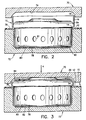
- the first step of the method of attachment is to place the mounting bracket 10 in a position for receiving the inflator 80 . From this position the cylindrical sleeve 16 of the mounting bracket 10 is then slid onto the inflator 80 until the inflator flange 84 butts against the flange seat 14 as shown in FIG. 2 , which illustrates the second step.
- the third step of the method is deforming the distal portion 18 of the sleeve 16 radially inwardly to form a continuous clamping band 20 underlying at least a portion of the inflator flange 84 as shown in FIG. 3 .
- the clamping band 20 clamps the inflator flange 84 against the flange seat 14 to prevent the inflator 10 from rotating with respect to the mounting bracket 10 and to secure the mounting bracket 10 to the inflator 80 .
- the mounting bracket 10 and inflator 80 are inverted from their usual orientation in an assembled airbag module 86 , as shown in FIG. 4 . References to orientation may be interpreted accordingly.
- a crimping die 70 and an inflator nest 72 are preferably used to crimp or deform the distal portion 18 of the sleeve 16 , although other tools or another method could be used to deform the distal portion 18 .
- the force applied does not necessarily have to be axial in nature.
- the crimping die 70 has a generally circular, or partial hemispheric, concave depression 74 sized to receive the distal portion 18 of the cylindrical sleeve 16 of the mounting bracket 10
- the inflator nest 72 has a generally flat face 76 with a generally cylindrical recess 78 sized to receive the inflator sidewall 82 .
- the inflator 80 with the mounting bracket 10 positioned thereon, is placed in the inflator nest 72 with the annular support 12 of the mounting bracket 10 abutting the flat face 76 of the inflator nest 72 .
- the concave depression 74 of the crimping die 70 is then placed over the distal portion 18 of the sleeve 16 and, as shown in FIG. 3 , a suitable amount of axial force, schematically illustrated by arrow A , is applied to the die 70 so that the die 70 crimps the distal portion 18 inwardly to form the clamping band 20 .
- a suitable amount of axial force schematically illustrated by arrow A
- the crimping die 70 applies the axial force A in a substantially even manner and reduces the chances of damaging the inflator 80 .
- FIG. 4 shows the mounting bracket 10 and inflator 80 , after axial crimping, secured in a driver side airbag module 86 .
- the airbag module 86 includes a module base plate 87 , an airbag cushion 88 and an airbag retainer 89 .
- the cylindrical sidewall 82 of the inflator 80 includes a plurality of gas exhaust ports 81 and contains a gas generant material that, once triggered by a remote collision sensor (not shown), provides the inflation gas for inflating the airbag cushion 88 .
- the annular support 12 of the mounting bracket 10 is positioned against the module base plate 87 so that a portion of the sidewall 82 containing the gas exhaust ports 81 extends through an inflator receiving hole 90 in the base plate 87 .
- the airbag cushion 88 has an open mouth 91 formed by a collar 92 that fits over the inflator 80 with the collar 92 positioned against the base plate 87 so that the gas exhaust ports 81 are located within the open mouth 91 .
- the airbag retainer 89 is positioned over the collar 92 of the airbag cushion 88 and the retainer 89 , collar 92 and annular support 12 are secured to the module base plate 87 with fasteners 93a,93b .
- the fasteners 93a,93b pass through, respectively, receiving holes 94a,94b in the retainer 89, receiving holes 95a,95b in the collar 92, receiving holes 96a,96b in the base plate 87 and receiving holes 22,23 in the annular support 12 , and are secured with nuts 98,99 or the like.
- inflation forces tend to push the inflator 80 downward and the clamping band 20 holds the inflator 80 within the airbag module 86 .
- the present invention therefore, provides a simple, reliable and low cost method of attaching a mounting bracket 10 to a driver side airbag inflator 80 that allows flexibility in the design of the mounting bracket 10 and inflator 80 .
- the mounting bracket 10 secures to the inflator 80 , mounts the inflator within an airbag module assembly 86 , and prevents inflator rotation with respect to the mounting bracket 10 .
- the mounting bracket 10 secures the inflator 80 to the airbag module assembly 86 , withstands the expansive forces during inflation of the airbag, and provides shake and rattle-free mounting.
Landscapes
- Engineering & Computer Science (AREA)
- Mechanical Engineering (AREA)
- Physics & Mathematics (AREA)
- Fluid Mechanics (AREA)
- Air Bags (AREA)
Applications Claiming Priority (2)
| Application Number | Priority Date | Filing Date | Title |
|---|---|---|---|
| US522836 | 1995-09-01 | ||
| US08/522,836 US5503426A (en) | 1995-09-01 | 1995-09-01 | Method of attaching a mounting bracket to an airbag inflator |
Publications (2)
| Publication Number | Publication Date |
|---|---|
| EP0761511A2 true EP0761511A2 (fr) | 1997-03-12 |
| EP0761511A3 EP0761511A3 (fr) | 1997-10-08 |
Family
ID=24082584
Family Applications (1)
| Application Number | Title | Priority Date | Filing Date |
|---|---|---|---|
| EP96306188A Withdrawn EP0761511A3 (fr) | 1995-09-01 | 1996-08-27 | Procédé de fixation d'un support de montage sur un gonfleur de sac gonflable |
Country Status (3)
| Country | Link |
|---|---|
| US (1) | US5503426A (fr) |
| EP (1) | EP0761511A3 (fr) |
| JP (1) | JP2960685B2 (fr) |
Families Citing this family (18)
| Publication number | Priority date | Publication date | Assignee | Title |
|---|---|---|---|---|
| US5813695A (en) * | 1996-09-17 | 1998-09-29 | United Technologies Corporation | Igniter post for airbag gas generator |
| DE59809761D1 (de) * | 1997-04-16 | 2003-11-06 | Volkswagen Ag | Lenksäule für Insassenschutzeinrichtungen und Sicherheitslenkungen |
| US5924728A (en) * | 1997-04-18 | 1999-07-20 | Autoliv Asp, Inc. | Fuel bottle attachment in fluid fueled inflator |
| US6364343B1 (en) | 2000-07-21 | 2002-04-02 | Daimlerchrysler Corporation | Grab handle bracket/airbag igniter retainer |
| DE10150275A1 (de) * | 2001-10-12 | 2003-04-17 | Zf Lemfoerder Metallwaren Ag | Gehäuse für einen aufblasbaren Gassack eines Kraftfahrzeuges |
| US6945554B2 (en) | 2002-08-26 | 2005-09-20 | Autoliv Asp, Inc. | Inflator press fit housing for inflatable curtains |
| US20090250914A1 (en) * | 2008-04-02 | 2009-10-08 | Autoliv Asp, Inc. | Module housing inflator flange |
| CN103465864B (zh) * | 2008-09-30 | 2017-03-15 | Trw空气气袋系统股份有限公司 | 气体发生器、其制造方法以及带有气体发生器的模块 |
| JP2010143562A (ja) * | 2009-04-02 | 2010-07-01 | Miyata:Kk | エアバッグ用インフレータおよびそのケースならびにエアバッグ用インフレータの製造法 |
| CN102380553A (zh) * | 2011-10-19 | 2012-03-21 | 芜湖市恒联机电有限公司 | 前左安全气囊安装支架的冲压模具 |
| JP6085453B2 (ja) | 2012-11-13 | 2017-02-22 | タカタ株式会社 | エアバッグ装置 |
| JP6215646B2 (ja) * | 2013-10-22 | 2017-10-18 | 株式会社ダイセル | インフレータとエアバッグの固定構造 |
| JP6434699B2 (ja) * | 2014-02-18 | 2018-12-05 | Joyson Safety Systems Japan株式会社 | エアバッグ装置 |
| WO2018110350A1 (fr) * | 2016-12-16 | 2018-06-21 | 株式会社ダイセル | Dispositif de retenue et générateur de gaz |
| JP6951182B2 (ja) * | 2016-12-16 | 2021-10-20 | 株式会社ダイセル | リテーナおよびガス発生器 |
| US12344183B2 (en) * | 2021-11-01 | 2025-07-01 | Autoliv Asp, Inc. | Systems and methods for improved airbag aspiration |
| CN116351961B (zh) * | 2023-03-28 | 2023-11-17 | 泰兴市唯艺传媒广告有限公司 | 一种广告展览架金属支架的加工处理装置 |
| WO2025038324A1 (fr) * | 2023-08-17 | 2025-02-20 | Autoliv Asp, Inc | Procédé d'assemblage d'un ensemble coussin de sécurité gonflable à aspiration |
Family Cites Families (8)
| Publication number | Priority date | Publication date | Assignee | Title |
|---|---|---|---|---|
| JPH0647362B2 (ja) * | 1986-02-28 | 1994-06-22 | 本田技研工業株式会社 | 自動車のエアバック用カバ− |
| JPS6460756A (en) * | 1987-08-28 | 1989-03-07 | Fuji Heavy Ind Ltd | Start controller for engine |
| US5286054A (en) * | 1989-12-04 | 1994-02-15 | Talley Automotive Products, Inc. | Aspirating/venting motor vehicle passenger airbag module |
| JPH0818527B2 (ja) * | 1990-12-18 | 1996-02-28 | ティーアールダブリュー・インコーポレーテッド | 車輌乗員拘束器の膨張装置 |
| US5141247A (en) * | 1990-12-18 | 1992-08-25 | Trw Inc. | Air bag inflator assembly |
| US5275431A (en) * | 1991-09-18 | 1994-01-04 | Trw Inc. | Air bag inflator assembly |
| US5342084A (en) * | 1993-07-02 | 1994-08-30 | Morton International, Inc. | Retention structure for a flange based inflator of an airbag restraint assembly |
| US5470101A (en) * | 1993-12-20 | 1995-11-28 | Alliedsignal Inc. | Driver side air bag module |
-
1995
- 1995-09-01 US US08/522,836 patent/US5503426A/en not_active Expired - Fee Related
-
1996
- 1996-08-27 EP EP96306188A patent/EP0761511A3/fr not_active Withdrawn
- 1996-08-30 JP JP8229864A patent/JP2960685B2/ja not_active Expired - Fee Related
Also Published As
| Publication number | Publication date |
|---|---|
| JPH09104314A (ja) | 1997-04-22 |
| EP0761511A3 (fr) | 1997-10-08 |
| US5503426A (en) | 1996-04-02 |
| JP2960685B2 (ja) | 1999-10-12 |
Similar Documents
| Publication | Publication Date | Title |
|---|---|---|
| US5503426A (en) | Method of attaching a mounting bracket to an airbag inflator | |
| US5547213A (en) | Press-on inflator mount | |
| JP3114395B2 (ja) | エアバッグ装置のインフレータ取付構造 | |
| JP3029284U (ja) | エアバッグ保持用リング及びこのリングを用いたクランプ装置 | |
| US5611563A (en) | Airbag inflator attachment with snap-in sleeve | |
| JP2522623B2 (ja) | 車輌乗員拘束装置 | |
| EP0631908B1 (fr) | Structure de rétention anti-cliqueter pour un gonfleur sans bride dans un système de retenue par sac gonflable | |
| EP0542418B1 (fr) | Système de retenue par coussin d'air | |
| EP0535852B1 (fr) | Dispositif de serrage pour coussin gonflable | |
| US20020084630A1 (en) | Retaining device | |
| JP3044721U (ja) | エアバッグインフレータ保持用タブ | |
| US5577763A (en) | Air bag mounting structure and method | |
| JPH082362A (ja) | エアバッグモジュール | |
| EP0551732A1 (fr) | Consoles de fixation d'un dispositif de protection d'un conducteur | |
| US5560643A (en) | Airbag module with clamped attachment of airbag cushion | |
| JP2501426B2 (ja) | エアバッグ束縛インフレ―タ組立体 | |
| US5553886A (en) | Flangeless airbag inflator with mounting adaptor | |
| US5547212A (en) | Passenger side airbag inflator with flanged mounting adapter | |
| JPH05162602A (ja) | エアバッグ装置のエアバッグ取付構造 | |
| JP3039624U (ja) | 組立/取付兼用手段を備えたエアバッグモジュール | |
| EP0788936A2 (fr) | Montage à force de gonfleur | |
| JPH09123854A (ja) | エアバッグ装置 |
Legal Events
| Date | Code | Title | Description |
|---|---|---|---|
| PUAI | Public reference made under article 153(3) epc to a published international application that has entered the european phase |
Free format text: ORIGINAL CODE: 0009012 |
|
| AK | Designated contracting states |
Kind code of ref document: A2 Designated state(s): DE FR GB IT |
|
| PUAL | Search report despatched |
Free format text: ORIGINAL CODE: 0009013 |
|
| AK | Designated contracting states |
Kind code of ref document: A3 Designated state(s): DE FR GB IT |
|
| 17P | Request for examination filed |
Effective date: 19971031 |
|
| 17Q | First examination report despatched |
Effective date: 19990729 |
|
| STAA | Information on the status of an ep patent application or granted ep patent |
Free format text: STATUS: THE APPLICATION IS DEEMED TO BE WITHDRAWN |
|
| 18D | Application deemed to be withdrawn |
Effective date: 19991209 |