EP0761520A1 - Arrangement de soupapes pour circuit de freinage assisté d'un système de freinage hydraulique - Google Patents
Arrangement de soupapes pour circuit de freinage assisté d'un système de freinage hydraulique Download PDFInfo
- Publication number
- EP0761520A1 EP0761520A1 EP96114511A EP96114511A EP0761520A1 EP 0761520 A1 EP0761520 A1 EP 0761520A1 EP 96114511 A EP96114511 A EP 96114511A EP 96114511 A EP96114511 A EP 96114511A EP 0761520 A1 EP0761520 A1 EP 0761520A1
- Authority
- EP
- European Patent Office
- Prior art keywords
- valve
- pressure
- chamber
- control
- piston
- Prior art date
- Legal status (The legal status is an assumption and is not a legal conclusion. Google has not performed a legal analysis and makes no representation as to the accuracy of the status listed.)
- Granted
Links
- 238000007789 sealing Methods 0.000 claims abstract description 34
- 230000008859 change Effects 0.000 claims description 4
- 238000000034 method Methods 0.000 description 5
- 230000008569 process Effects 0.000 description 5
- 230000001276 controlling effect Effects 0.000 description 4
- 238000011982 device technology Methods 0.000 description 4
- 238000006243 chemical reaction Methods 0.000 description 3
- 230000010354 integration Effects 0.000 description 3
- 230000001133 acceleration Effects 0.000 description 2
- 230000001419 dependent effect Effects 0.000 description 2
- 230000000694 effects Effects 0.000 description 2
- 238000009434 installation Methods 0.000 description 2
- 230000004913 activation Effects 0.000 description 1
- 238000013459 approach Methods 0.000 description 1
- 230000008901 benefit Effects 0.000 description 1
- 230000005540 biological transmission Effects 0.000 description 1
- 230000003247 decreasing effect Effects 0.000 description 1
- 230000000881 depressing effect Effects 0.000 description 1
- 238000011161 development Methods 0.000 description 1
- 230000018109 developmental process Effects 0.000 description 1
- 238000006073 displacement reaction Methods 0.000 description 1
- 238000005553 drilling Methods 0.000 description 1
- 230000005489 elastic deformation Effects 0.000 description 1
- 230000002349 favourable effect Effects 0.000 description 1
- 238000007667 floating Methods 0.000 description 1
- 239000012530 fluid Substances 0.000 description 1
- 230000006872 improvement Effects 0.000 description 1
- 238000004137 mechanical activation Methods 0.000 description 1
- 238000005192 partition Methods 0.000 description 1
- 238000003825 pressing Methods 0.000 description 1
- 230000010349 pulsation Effects 0.000 description 1
- 230000001105 regulatory effect Effects 0.000 description 1
- 230000007363 regulatory process Effects 0.000 description 1
- 230000000284 resting effect Effects 0.000 description 1
- 230000035945 sensitivity Effects 0.000 description 1
Images



Classifications
-
- B—PERFORMING OPERATIONS; TRANSPORTING
- B60—VEHICLES IN GENERAL
- B60T—VEHICLE BRAKE CONTROL SYSTEMS OR PARTS THEREOF; BRAKE CONTROL SYSTEMS OR PARTS THEREOF, IN GENERAL; ARRANGEMENT OF BRAKING ELEMENTS ON VEHICLES IN GENERAL; PORTABLE DEVICES FOR PREVENTING UNWANTED MOVEMENT OF VEHICLES; VEHICLE MODIFICATIONS TO FACILITATE COOLING OF BRAKES
- B60T8/00—Arrangements for adjusting wheel-braking force to meet varying vehicular or ground-surface conditions, e.g. limiting or varying distribution of braking force
- B60T8/32—Arrangements for adjusting wheel-braking force to meet varying vehicular or ground-surface conditions, e.g. limiting or varying distribution of braking force responsive to a speed condition, e.g. acceleration or deceleration
- B60T8/34—Arrangements for adjusting wheel-braking force to meet varying vehicular or ground-surface conditions, e.g. limiting or varying distribution of braking force responsive to a speed condition, e.g. acceleration or deceleration having a fluid pressure regulator responsive to a speed condition
- B60T8/36—Arrangements for adjusting wheel-braking force to meet varying vehicular or ground-surface conditions, e.g. limiting or varying distribution of braking force responsive to a speed condition, e.g. acceleration or deceleration having a fluid pressure regulator responsive to a speed condition including a pilot valve responding to an electromagnetic force
- B60T8/3615—Electromagnetic valves specially adapted for anti-lock brake and traction control systems
- B60T8/3655—Continuously controlled electromagnetic valves
- B60T8/366—Valve details
- B60T8/367—Seat valves, e.g. poppet valves
-
- B—PERFORMING OPERATIONS; TRANSPORTING
- B60—VEHICLES IN GENERAL
- B60T—VEHICLE BRAKE CONTROL SYSTEMS OR PARTS THEREOF; BRAKE CONTROL SYSTEMS OR PARTS THEREOF, IN GENERAL; ARRANGEMENT OF BRAKING ELEMENTS ON VEHICLES IN GENERAL; PORTABLE DEVICES FOR PREVENTING UNWANTED MOVEMENT OF VEHICLES; VEHICLE MODIFICATIONS TO FACILITATE COOLING OF BRAKES
- B60T13/00—Transmitting braking action from initiating means to ultimate brake actuator with power assistance or drive; Brake systems incorporating such transmitting means, e.g. air-pressure brake systems
- B60T13/10—Transmitting braking action from initiating means to ultimate brake actuator with power assistance or drive; Brake systems incorporating such transmitting means, e.g. air-pressure brake systems with fluid assistance, drive, or release
- B60T13/12—Transmitting braking action from initiating means to ultimate brake actuator with power assistance or drive; Brake systems incorporating such transmitting means, e.g. air-pressure brake systems with fluid assistance, drive, or release the fluid being liquid
- B60T13/16—Transmitting braking action from initiating means to ultimate brake actuator with power assistance or drive; Brake systems incorporating such transmitting means, e.g. air-pressure brake systems with fluid assistance, drive, or release the fluid being liquid using pumps directly, i.e. without interposition of accumulators or reservoirs
- B60T13/161—Systems with master cylinder
- B60T13/167—In combination with distributor valve
-
- B—PERFORMING OPERATIONS; TRANSPORTING
- B60—VEHICLES IN GENERAL
- B60T—VEHICLE BRAKE CONTROL SYSTEMS OR PARTS THEREOF; BRAKE CONTROL SYSTEMS OR PARTS THEREOF, IN GENERAL; ARRANGEMENT OF BRAKING ELEMENTS ON VEHICLES IN GENERAL; PORTABLE DEVICES FOR PREVENTING UNWANTED MOVEMENT OF VEHICLES; VEHICLE MODIFICATIONS TO FACILITATE COOLING OF BRAKES
- B60T13/00—Transmitting braking action from initiating means to ultimate brake actuator with power assistance or drive; Brake systems incorporating such transmitting means, e.g. air-pressure brake systems
- B60T13/10—Transmitting braking action from initiating means to ultimate brake actuator with power assistance or drive; Brake systems incorporating such transmitting means, e.g. air-pressure brake systems with fluid assistance, drive, or release
- B60T13/66—Electrical control in fluid-pressure brake systems
- B60T13/68—Electrical control in fluid-pressure brake systems by electrically-controlled valves
- B60T13/686—Electrical control in fluid-pressure brake systems by electrically-controlled valves in hydraulic systems or parts thereof
-
- B—PERFORMING OPERATIONS; TRANSPORTING
- B60—VEHICLES IN GENERAL
- B60T—VEHICLE BRAKE CONTROL SYSTEMS OR PARTS THEREOF; BRAKE CONTROL SYSTEMS OR PARTS THEREOF, IN GENERAL; ARRANGEMENT OF BRAKING ELEMENTS ON VEHICLES IN GENERAL; PORTABLE DEVICES FOR PREVENTING UNWANTED MOVEMENT OF VEHICLES; VEHICLE MODIFICATIONS TO FACILITATE COOLING OF BRAKES
- B60T8/00—Arrangements for adjusting wheel-braking force to meet varying vehicular or ground-surface conditions, e.g. limiting or varying distribution of braking force
- B60T8/32—Arrangements for adjusting wheel-braking force to meet varying vehicular or ground-surface conditions, e.g. limiting or varying distribution of braking force responsive to a speed condition, e.g. acceleration or deceleration
- B60T8/321—Arrangements for adjusting wheel-braking force to meet varying vehicular or ground-surface conditions, e.g. limiting or varying distribution of braking force responsive to a speed condition, e.g. acceleration or deceleration deceleration
- B60T8/3225—Systems specially adapted for single-track vehicles, e.g. motorcycles
-
- B—PERFORMING OPERATIONS; TRANSPORTING
- B60—VEHICLES IN GENERAL
- B60T—VEHICLE BRAKE CONTROL SYSTEMS OR PARTS THEREOF; BRAKE CONTROL SYSTEMS OR PARTS THEREOF, IN GENERAL; ARRANGEMENT OF BRAKING ELEMENTS ON VEHICLES IN GENERAL; PORTABLE DEVICES FOR PREVENTING UNWANTED MOVEMENT OF VEHICLES; VEHICLE MODIFICATIONS TO FACILITATE COOLING OF BRAKES
- B60T8/00—Arrangements for adjusting wheel-braking force to meet varying vehicular or ground-surface conditions, e.g. limiting or varying distribution of braking force
- B60T8/32—Arrangements for adjusting wheel-braking force to meet varying vehicular or ground-surface conditions, e.g. limiting or varying distribution of braking force responsive to a speed condition, e.g. acceleration or deceleration
- B60T8/34—Arrangements for adjusting wheel-braking force to meet varying vehicular or ground-surface conditions, e.g. limiting or varying distribution of braking force responsive to a speed condition, e.g. acceleration or deceleration having a fluid pressure regulator responsive to a speed condition
- B60T8/343—Systems characterised by their lay-out
- B60T8/344—Hydraulic systems
- B60T8/348—4 Channel systems
-
- B—PERFORMING OPERATIONS; TRANSPORTING
- B60—VEHICLES IN GENERAL
- B60T—VEHICLE BRAKE CONTROL SYSTEMS OR PARTS THEREOF; BRAKE CONTROL SYSTEMS OR PARTS THEREOF, IN GENERAL; ARRANGEMENT OF BRAKING ELEMENTS ON VEHICLES IN GENERAL; PORTABLE DEVICES FOR PREVENTING UNWANTED MOVEMENT OF VEHICLES; VEHICLE MODIFICATIONS TO FACILITATE COOLING OF BRAKES
- B60T8/00—Arrangements for adjusting wheel-braking force to meet varying vehicular or ground-surface conditions, e.g. limiting or varying distribution of braking force
- B60T8/32—Arrangements for adjusting wheel-braking force to meet varying vehicular or ground-surface conditions, e.g. limiting or varying distribution of braking force responsive to a speed condition, e.g. acceleration or deceleration
- B60T8/34—Arrangements for adjusting wheel-braking force to meet varying vehicular or ground-surface conditions, e.g. limiting or varying distribution of braking force responsive to a speed condition, e.g. acceleration or deceleration having a fluid pressure regulator responsive to a speed condition
- B60T8/40—Arrangements for adjusting wheel-braking force to meet varying vehicular or ground-surface conditions, e.g. limiting or varying distribution of braking force responsive to a speed condition, e.g. acceleration or deceleration having a fluid pressure regulator responsive to a speed condition comprising an additional fluid circuit including fluid pressurising means for modifying the pressure of the braking fluid, e.g. including wheel driven pumps for detecting a speed condition, or pumps which are controlled by means independent of the braking system
- B60T8/404—Control of the pump unit
- B60T8/4054—Control of the pump unit involving the delivery pressure control
-
- B—PERFORMING OPERATIONS; TRANSPORTING
- B60—VEHICLES IN GENERAL
- B60T—VEHICLE BRAKE CONTROL SYSTEMS OR PARTS THEREOF; BRAKE CONTROL SYSTEMS OR PARTS THEREOF, IN GENERAL; ARRANGEMENT OF BRAKING ELEMENTS ON VEHICLES IN GENERAL; PORTABLE DEVICES FOR PREVENTING UNWANTED MOVEMENT OF VEHICLES; VEHICLE MODIFICATIONS TO FACILITATE COOLING OF BRAKES
- B60T8/00—Arrangements for adjusting wheel-braking force to meet varying vehicular or ground-surface conditions, e.g. limiting or varying distribution of braking force
- B60T8/32—Arrangements for adjusting wheel-braking force to meet varying vehicular or ground-surface conditions, e.g. limiting or varying distribution of braking force responsive to a speed condition, e.g. acceleration or deceleration
- B60T8/34—Arrangements for adjusting wheel-braking force to meet varying vehicular or ground-surface conditions, e.g. limiting or varying distribution of braking force responsive to a speed condition, e.g. acceleration or deceleration having a fluid pressure regulator responsive to a speed condition
- B60T8/40—Arrangements for adjusting wheel-braking force to meet varying vehicular or ground-surface conditions, e.g. limiting or varying distribution of braking force responsive to a speed condition, e.g. acceleration or deceleration having a fluid pressure regulator responsive to a speed condition comprising an additional fluid circuit including fluid pressurising means for modifying the pressure of the braking fluid, e.g. including wheel driven pumps for detecting a speed condition, or pumps which are controlled by means independent of the braking system
- B60T8/4072—Systems in which a driver input signal is used as a control signal for the additional fluid circuit which is normally used for braking
-
- B—PERFORMING OPERATIONS; TRANSPORTING
- B60—VEHICLES IN GENERAL
- B60T—VEHICLE BRAKE CONTROL SYSTEMS OR PARTS THEREOF; BRAKE CONTROL SYSTEMS OR PARTS THEREOF, IN GENERAL; ARRANGEMENT OF BRAKING ELEMENTS ON VEHICLES IN GENERAL; PORTABLE DEVICES FOR PREVENTING UNWANTED MOVEMENT OF VEHICLES; VEHICLE MODIFICATIONS TO FACILITATE COOLING OF BRAKES
- B60T8/00—Arrangements for adjusting wheel-braking force to meet varying vehicular or ground-surface conditions, e.g. limiting or varying distribution of braking force
- B60T8/32—Arrangements for adjusting wheel-braking force to meet varying vehicular or ground-surface conditions, e.g. limiting or varying distribution of braking force responsive to a speed condition, e.g. acceleration or deceleration
- B60T8/34—Arrangements for adjusting wheel-braking force to meet varying vehicular or ground-surface conditions, e.g. limiting or varying distribution of braking force responsive to a speed condition, e.g. acceleration or deceleration having a fluid pressure regulator responsive to a speed condition
- B60T8/48—Arrangements for adjusting wheel-braking force to meet varying vehicular or ground-surface conditions, e.g. limiting or varying distribution of braking force responsive to a speed condition, e.g. acceleration or deceleration having a fluid pressure regulator responsive to a speed condition connecting the brake actuator to an alternative or additional source of fluid pressure, e.g. traction control systems
- B60T8/4809—Traction control, stability control, using both the wheel brakes and other automatic braking systems
- B60T8/4827—Traction control, stability control, using both the wheel brakes and other automatic braking systems in hydraulic brake systems
Definitions
- the invention relates to a valve arrangement for an external force brake circuit of a hydraulic brake system according to the preamble of claim 1.
- the invention relates to a valve arrangement by means of which the external force is applied to the application member via a dynamic pressure generated when a throttle gap flows through a throttle gap , which can be set in a defined manner by adjusting the throttle gap, and which can apply a defined residual braking force to the application element with little effort in terms of device technology if the external power support fails.
- Hydraulic braking systems for motor vehicles are nowadays usually implemented as auxiliary braking systems or external braking systems.
- the energy required to generate the braking force comes from the physical force of the vehicle driver and one or more energy supply devices, i.e. during braking, part of the braking force is applied directly to the application elements via a master cylinder connected to a manually operated brake pedal, while the other part of the braking force is applied as a servo force by, for example, a hydraulic pump.
- the energy required to generate the braking power comes from one or more energy supply devices, with the exception of the physical power of the vehicle driver, that is to say the master cylinder connected to the brake pedal does not serve to apply the braking force directly to the application elements, but instead only the control of the servo force acting on the clamping elements.
- the master cylinder connected to the brake pedal does not serve to apply the braking force directly to the application elements, but instead only the control of the servo force acting on the clamping elements.
- Common to both types of brake systems is that they have a servo or power brake circuit.
- a brake booster for a power brake system in which the servo force is generated via a pressure circulation system.
- the brake booster has a pressure chamber connected to the outlet of a hydraulic pump, which is connected to the application members, and an outlet chamber connected to a reservoir, which is connected to the pressure chamber via a throttle valve.
- the throttle valve has a valve body which, together with a socket arranged in the brake booster, limits the throttle or valve gap of the throttle valve and is connected to the brake pedal, so that the valve gap of the throttle valve is adjustable by one depending on the position of the brake pedal to generate back pressure proportional to the stroke of the brake pedal in the pressure chamber.
- the dynamic pressure is supplied to the clamping elements via a piston guided in the pressure chamber with a through hole.
- the dynamic pressure also acts on the brake pedal via the hydraulic active surface of the valve body facing the piston. This feedback of the dynamic pressure applied to the throttle valve towards the brake pedal enables the brake pedal to be actuated sensitively, taking into account the brake pressure prevailing in the application elements.
- a further valve element which can be brought into contact with the valve body if it has been moved into the socket to such an extent that the throttle valve is closed is.
- the further valve element can now be displaced via the valve body against the force of a return spring in the direction of the piston guided in the pressure chamber in order to close the through hole in the piston, so that the clamping elements can be controlled via the piston.
- DE-PS 1 180 259 describes a brake booster which differs from the brake booster described above essentially in that the piston arranged in the pressure chamber is acted upon mechanically by the valve body connected to the brake pedal, even in normal braking operation, while instead of the other A check valve is arranged in the through bore of the piston in the valve element, which is biased into its closed position counter to the actuating direction of the valve body and only releases the pressure medium in the direction of the application members.
- an additional pressure chamber with a further piston accommodated therein is provided, which is arranged between the valve body of the throttle valve and the piston in the pressure chamber in order to apply a reaction force proportional to the dynamic pressure to the valve body and thus to the brake pedal.
- a disadvantage of this brake booster can be seen in the fact that not only the integration of the residual brake function in the brake booster, but also the feedback of the dynamic pressure applied to the throttle valve to the brake pedal requires a great deal of technical equipment, ie a large number of components and a large installation space on the valve side.
- the mass of the further piston when the brake pedal is actuated, the mass of the further piston must also be moved and the frictional force between the further piston and the inner wall of the additional pressure chamber must be overcome, which, if the servo force fails, leads to Generation of the required residual braking force on the brake pedal, the required actuation force is additionally increased.
- DE-PS 1 037 287 shows a brake booster for a power brake system in which the brake circuit is separate from the servo circuit.
- This prior art also works with a throttle valve based on the dynamic pressure principle.
- a valve body extends through the drain chamber of this brake booster, one end of which can be controlled hydraulically by the master cylinder connected to the brake pedal, and the other end of which projects into the pressure chamber of the servo circuit.
- the valve body is provided with a central blind bore, at the bottom of which a transverse bore is provided in order to connect the pressure chamber of the servo circuit to the drain chamber.
- the end of the valve body protruding into the pressure chamber of the servo circuit forms the throttle valve with the closed bottom of a plunger arranged concentrically to the valve body and sealingly extending through a partition between the pressure chamber of the servo circuit and the pressure chamber of the brake circuit.
- the hydraulic active surface of the valve body on the master cylinder side is so large that, in normal braking operation, it requires a large pressure medium or stroke on the master cylinder with a correspondingly high actuating force on the brake pedal adjust the valve gap of the throttle valve and thus the servo force.
- the regulating process which occurs when the valve body is displaced by applying pressure via the master cylinder to the plunger at the valve gap of the throttle valve leads to the fact that the brake pedal acted upon by the actuating force yields, which is also referred to as the brake pedal running away.
- the use of electromagnetically controlled ball seat valves in pressure modulators for hydraulic brake systems with an anti-lock braking system is known in principle.
- the ball seat valve works as a switching valve, the valve ball of which can be displaced indirectly via an electromagnetically adjustable pressure relief piston of the pressure modulator or directly by a specially provided electromagnet to interrupt the connection between the master cylinder and the wheel brake cylinder, so that during ABS operation
- the brake pressure in the wheel brake cylinder can be regulated independently of the pressure in the master cylinder via the pressure relief piston.
- auxiliary or external brake systems in which the servo power is generated by a hydraulic pump according to the dynamic pressure principle, with regard to a favorable integration of the residual brake function in terms of device technology, a satisfactory feedback of the brake pressure present in the application members to the brake pedal and an appropriate actuation force requirement on the brake pedal and sufficient braking force on the application elements are in need of improvement.
- the invention is therefore based on the object of creating a valve arrangement for an external force brake circuit of a hydraulic brake system, by means of which, with little expenditure on device technology, both in normal braking operation and in the event of servo force failure, a sufficient braking force on the application members can be applied with a good pedal feel.
- the valve arrangement has a throttle valve with a valve body which controllably limits a throttle gap which is forced to flow in the power-assisted braking mode with a pressure medium in order to set a defined dynamic pressure which can be applied to an application element of the brake system in a pressure chamber in which a valve piston with a through bore is accommodated, which Failure of the external power support to generate a residual brake pressure in the pressure chamber is displaceable via the valve body with the through bore closed, the throttle gap being formed on the through bore of the valve piston.
- valve body not only limits the throttle gap, but also serves as a closure element for the through-hole in the valve piston and for direct control of the valve piston in the event of failure of the external power support, while that is pending in the pressure chamber Back pressure or the brake pressure generated by the closed valve piston is present immediately, ie without the interposition of further components on the valve body and can thus be reported back to the brake pedal.
- the valve body not only limits the throttle gap, but also serves as a closure element for the through-hole in the valve piston and for direct control of the valve piston in the event of failure of the external power support, while that is pending in the pressure chamber Back pressure or the brake pressure generated by the closed valve piston is present immediately, ie without the interposition of further components on the valve body and can thus be reported back to the brake pedal.
- valve body of the throttle valve of the valve assembly for adjusting the throttle gap can be controlled hydraulically and electromagnetically, so that an anti-lock control (ABS) can be easily implemented, in which the hydraulically adjusted throttle gap is corrected electromagnetically in order to generate a dynamic pressure adapted to the braking conditions , which is applied as brake pressure to the application element.
- ABS anti-lock control
- a valve arrangement according to claim 3, the throttle valve of which has a control chamber in which a control piston is slidably guided, by means of which the valve body can also be mechanically displaced to adjust the throttle gap, is particularly suitable for integral brake systems on motorcycles, not least due to its compact structure, in which the front wheel brake circuit and the rear wheel brake circuit can in principle be controlled hydraulically separately, but the rear wheel brake circuit is also to be controlled via the front wheel brake circuit.
- the throttle valve of the valve arrangement is designed as a ball seat valve with a spherical valve body which, together with an annular sealing seat on the through bore of the valve piston, delimits the throttle gap.
- the throttle cross section can advantageously be set reliably and precisely by means of a spherical valve body in order to generate a defined dynamic pressure.
- a spherical valve body interacting with an annular sealing seat is also ideally suited for sealing the valve piston, since the valve body can center itself on the sealing seat.
- valve arrangement is supplemented by a further throttle valve, which is arranged in the flow direction of the pressure medium in front of the pressure chamber of the first throttle valve and whose throttle gap can be adjusted electromagnetically independently of the throttle valve in order to generate a defined dynamic pressure which the brake system application element can be applied.
- ASR traction control
- driving dynamics control into the hydraulic brake system.
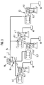
- valve 1 shows the valve arrangement according to the invention in the unactuated state.
- the valve arrangement has a throttle valve 2, which has a pressure chamber 4, in which a valve piston 6 is slidably arranged.
- the valve piston 6 has a through bore 8, on which it forms a throttle gap 12 together with a valve body 10.
- the throttle gap 12 is forced to flow through a pressure medium, preferably brake fluid, in the power-assisted braking operation and is adjustable by actuating the valve body 10, so that a defined dynamic pressure is generated in the pressure chamber 4.
- the dynamic pressure is applied to generate a braking force on a brake caliper 14 of the brake system serving as an application member. If the external power support fails, the valve piston 6 can be moved via the valve body 10 in the pressure chamber 4, the valve body 10 closing the through bore 8, so that a residual brake pressure is generated in the pressure chamber 4.
- the throttle valve 2 is designed as a 2/2 ball seat valve and has a three-chamber valve housing 16 which, in addition to the pressure chamber 4, delimits a control chamber 18 and an outlet chamber 20 which are separated from one another by a wall 22 of the valve housing 16.
- a control piston 24 is slidably arranged, the hydraulic or for an anti-lock control (ABS) can be moved electromagnetically in the axial direction of the control chamber 18.
- the control piston 24 consists of an armature 26 guided in the control chamber 18 and a valve bolt 28 arranged centrally to the armature 26, which extends through the wall 22 between the control chamber 18 and the drain chamber 20 in a sealed manner by means of a sealing element 30 and projects into the drain chamber 20.
- valve bolt 28 of the control piston 24 which is hydraulically tightly guided in the wall 22, has a smaller diameter than the armature 26 of the control piston 24.
- the control piston 24 can be substantially completely flushed by the pressure medium in the control chamber 18 are, for which purpose a bore 32 is formed in the armature 26, which connects the left side of the armature 26 in FIG. 1 with its right side in FIG. 1.
- a magnet coil 34 is arranged, which at least partially concentrically surrounds the armature 26 of the control piston 24.
- the magnet coil 34 is sealed off from the control chamber 18 by means of a sleeve and sealing elements embedded in the control chamber 18 (for the sake of clarity, not provided with reference numerals in FIG. 1).
- the throttle valve 2 can be controlled to change the throttle gap 12 independently of the actuation of the brake pedal 62, the control piston 24 being axially displaced, as will be explained in more detail below.
- the magnetic drive is designed with a corresponding current-force characteristic.
- control chamber 18 On the side of the armature 26 opposite the drain chamber 20, a stop 36 is formed in the control chamber 18 or on the armature 26, which limits the path of the control piston 24 in the control chamber 18 to the left in FIG. 1.
- control chamber 18 has a connection 38 via which the control piston 24 can be controlled hydraulically. In the illustrated In this case, the connection 38 opens out on the side of the control piston 24 facing away from the discharge chamber 20, preferably centrally in the control chamber 18.
- connection 38 could also extend radially through the valve housing 16 and open into the control chamber 18 on the side of the control piston 24 facing the discharge chamber 20.
- the valve body 10 is arranged, which is designed as a metallic ball, which can be acted upon mechanically with a force by way of the valve bolt 28 which extends through the wall 22 between the control chamber 18 and the drain chamber 20.
- the valve body 10 can only be subjected to a compressive force via the valve pin 28 of the control piston 24, since the valve body 10 and the valve pin 28 are two separate components.
- the drain chamber 20 is also provided with a connection 40 via which the pressure medium can flow out of the drain chamber 20.
- a shoulder 42 is provided, which forms a stop on the discharge chamber side for the valve piston 6 received in the pressure chamber 4 and lying on one axis with the control piston 24.
- annular sealing seat 44 is attached on the discharge chamber side, which, like the through bore 8, is centered on the central axis of the valve piston 6 and cooperates with the valve body 10 to limit the throttle gap 12 If the external power support fails, the valve body 10 comes into tight contact.
- a return spring 46 is received, which is located on a pressure chamber side Shoulder 48 of the valve piston 6 supports and presses the valve body 10 against the valve pin 28 of the control piston 24.
- the valve piston 6 is provided on its outer circumference with a sealing element 50, so that only the throttle gap 12 hydraulically connects the pressure chamber 4 to the outlet chamber 20 via the through bore 8 of the valve piston 6, or a residual brake pressure can be generated in the pressure chamber 4 if the external power support fails after the valve body 10 has closed the through hole 8 in the valve piston 6 on the sealing seat 44.
- a piston spring 52 is received in the pressure chamber 4 and biases the valve piston 6 onto the shoulder 42 of the valve housing 16 with a force that is greater than the restoring force of the restoring spring 46.
- the pressure chamber 4 also has a connection 54.
- the throttle valve 2 is in the uncontrolled state in the passage zero position, in which the valve piston 6 is biased by the piston spring 52 against the shoulder 42 of the valve housing 16, while the shoulder 48th of the valve piston 6 supporting return spring 46 presses the control piston 24 against the stop 36 in the control chamber 18 via the frictional connection between the valve body 10 and the valve bolt 28, the throttle gap 12 being opened to the maximum.
- the possible stroke of the control piston 24 in the control chamber 18 is composed of the closing path s of the throttle gap 12, which the valve body 10 has to cover until it has been brought from its pretensioned starting position to rest on the sealing seat 44 of the valve piston 6, and the stroke 1 of the Valve piston 6, which it must cover until it has been brought from its pretensioned starting position to bear against the valve housing 16 at the end of the pressure chamber 4 facing away from the discharge chamber 20.
- valve arrangement described above is connected to the hydraulic brake system as follows.
- a master cylinder 56 is used, in the case shown a tandem master cylinder which has two pressure chambers 58, 60 and can be actuated via a brake pedal 62.
- the brake pedal 62 is operatively connected via a piston rod 64 to a first piston 66 of the master cylinder 56, which hydraulically limits the first pressure chamber 58 of the master cylinder 56 on the brake pedal side.
- a second piston 68 is arranged between the first pressure chamber 58 and the second pressure chamber 60 of the master cylinder 56 and hydraulically separates the first and the second pressure chamber 58, 60 from one another.
- the first and second pressure chambers 58, 60 are each connected to an expansion tank 72 via a connection 70.
- the second pressure chamber 60 of the master cylinder 56 is hydraulically connected via a control line 74 to the connection 38 of the control chamber 18 of the throttle valve 2.
- the pressure chamber 4 of the throttle valve 2 is hydraulically connected at its connection 54 via a pressure line 76 to the outlet of a hydraulic pump 78, the input of which is connected via a suction line 80 to a reservoir 82 for the pressure medium and which, in the power-assisted braking mode, causes the flow through the throttle gap 12 .
- a check valve 84 is connected in the pressure line 76, which prevents the pressure medium from flowing back in the direction of the hydraulic pump 78.
- a pressure line 86 which leads to the brake caliper 14, branches off from the pressure line 76 between the check valve 84 and the pressure chamber 4 of the throttle valve 2.
- the brake caliper 14 in the case shown a floating caliper, has a piston-cylinder arrangement 88 with a pressure chamber 90 in which a piston 92 is hydraulically sealed.
- the pressure chamber 90 is connected to the pressure line 86, so that the piston 92 can be acted upon by the dynamic pressure generated by the hydraulic pump 78 and controlled by the throttle valve 2.
- the brake caliper 14 is provided with brake pads 94, which are pressed in a manner known per se when the piston-cylinder arrangement 88 is pressurized via the piston 92 against a brake disk 96.
- the drain chamber 20 of the throttle valve 2 is connected to the reservoir 82 via a return line 98.
- a pressure-maintaining valve 100 which is biased in the direction of the outlet chamber 20, is optionally connected into the return line 98 and depending on the spatial arrangement of the storage container 82.
- a pedal switch 102 that can be actuated mechanically via the brake pedal 62 and / or an electro-hydraulic pressure switch 104 connected into the control line 74 is provided, the function of which will be explained in the following.
- the hydraulic pump 78, the pressure line 76, the throttle valve 2 connected to the reservoir 82 via the return line 98, the pressure line 86 and the piston-cylinder arrangement 88 of the brake caliper 14 form an external force brake circuit A which is integrated via the lockable valve piston 6 Residual braking function, which can be controlled electromagnetically by means of the magnetic coil 34 or via a hydraulic control circuit B which is hydraulically separated from the external force brake circuit A and which consists of the piston 68 of the master cylinder 56, the second pressure chamber 60 of the master cylinder 56, the control line 74, the control chamber 18 of the throttle valve 2 and the control piston 24 of the throttle valve 2.
- valve arrangement according to the invention for controlling the piston-cylinder arrangement 88 of the brake caliper 14 for a wheel of the motor vehicle is shown in FIG. 1.
- the Activation of the piston-cylinder arrangements of further brake calipers for the further wheels of the motor vehicle can accordingly take place via further valve arrangements according to the invention, which via a branch (not shown) of the control line 74 to the second pressure chamber 60 of the master cylinder 56 or via a control line 74 ' the first pressure chamber 58 of the master cylinder 56 are connected, as will be explained in more detail below.
- the hydraulic control of the valve arrangement according to the invention can of course also be carried out by means of a single-chamber master cylinder. The same applies to the second embodiment of the invention shown in FIG. 2.
- the hydraulic pump 78 is simultaneously started via the pedal switch 102 actuated by the brake pedal 62 or, when a predetermined signal pressure in the hydraulic control circuit B is exceeded, via the electro-hydraulic pressure switch 104, for which purpose the pedal switch 102 or the electro-hydraulic pressure switch 104 emits an electrical signal provides that starts an electric motor (not shown) that is drivingly connected to the hydraulic pump 78 or engages an electromagnetic clutch (not shown) that connects the hydraulic pump 78 to a rotating shaft of the motor or a wheel of the motor vehicle.
- the hydraulic pump 78 could also be operated during the entire service life of the motor vehicle.
- the hydraulic pump 78 now sucks the pressure medium from the reservoir 82 via the suction line 80 and conveys it via the check valve 84 and the pressure line 76 into the pressure chamber 4 of the throttle valve 2. From the pressure chamber 4, the pressure medium flows through the through bore 8 in the valve piston 6 the throttle gap 12 into the drain chamber 20 and from there via the return line 98 and the pressure control valve 100 back to the reservoir 82. Since at the beginning of the actuation of the brake pedal 62 the control piston 24 of the throttle valve 2 and thus the valve body 10 only slightly towards the sealing seat 44 are displaced on the valve piston 6 so that the throttle gap 12 is almost completely open, the hydraulic pump 78 circulates the pressure medium largely without pressure via the throttle valve 2.
- valve body 10 is now pushed over the valve pin 28 of the hydraulically actuated control piston 24 against the force of the return spring 46 in the direction of the sealing seat 44, with a force that is equal to the product of the control pressure applied in the control chamber 18 by the master cylinder 56 and by the cross-sectional area of the Valve pin 28 is specific hydraulic effective area of the control piston 24.
- the throttle gap 12 is reduced, as a result of which the flow cross section for the pressure medium circulated by the hydraulic pump 78 via the pressure line 76 and the pressure chamber 4 is reduced.
- the back pressure generated in front of the throttle gap 12 essentially depends on the volume flow of the hydraulic pump 78 and the flow resistance of the throttle valve 2, but is more or less proportional to the control pressure in the control chamber 18 of the throttle valve 2.
- the proportionality factor between this control pressure and the dynamic pressure generated in front of the throttle gap 12 is determined by the ratio of the hydraulic effective area of the control piston 24 in the control chamber 18, ie the cross-sectional area of the valve pin 28, to the effective hydraulic effective area of the valve body 10 when it is in contact with the sealing seat 44 appropriate dimensioning of these active surfaces can be set on the one hand the desired pressure gain in the power brake circuit A.
- the reaction force applied to the effective hydraulic effective area of the valve body 10 by the dynamic pressure on the valve body 10 can be adjusted such that the pressure column of the hydraulic control circuit B between the control piston 24 of the throttle valve 2 and the second piston 68 of the master cylinder 56 and the closed pressure column between the second piston 68 and the first piston 66 of the master cylinder 56 there is an appropriate feedback of the dynamic pressure towards the brake pedal 62 in order to ensure a good pedal feel and thus a sensitive actuation to enable the brake pedal 62. Since the throttle gap 12 of the throttle valve 2 is continuously adjusted and is not completely closed against the dynamic pressure in the power-assisted braking operation, there are in particular no control pressure surges which could affect the brake pedal 62.
- the control pressure in the hydraulic control circuit B is reduced by relieving the brake pedal 62, and the control piston 24 of the throttle valve 2 moves together with the valve body 10 to enlarge the throttle gap 12 into its starting position, countering it the reducing control pressure in the control chamber 18 via the valve body 10 is loaded by the back pressure of the circulating pressure medium in the pressure chamber 4, which becomes smaller as the throttle gap 12 increases, and the force of the return spring 46 is loaded.
- the required residual braking force can be applied to the brake pedal 62 via the valve piston 6 with appropriate feedback.
- the valve body 10 which is displaced via the hydraulically actuated control piston 24 against the force of the return spring 46 by the closing path s of the throttle gap 12, closes the through bore 8 in the valve piston 6 on the sealing seat 44 so that it is sealed by further displacement of the closed valve piston 6 via the valve body 10 and the control piston 24 in the pressure chamber 4 generates a residual brake pressure.
- the residual brake pressure propagates via the pressure line 86 to the piston-cylinder arrangement 88 of the brake caliper 14, so that a residual braking force is applied to the brake disc 96 via the piston 92 and the brake pads 94.
- the maximum possible useful stroke of the valve arrangement for applying the residual brake pressure is equal to the stroke l of the valve piston 6. If the external power support fails, it is particularly advantageous for applying the residual brake pressure in the pressure chamber 4 that the valve body 10 is a ball, since the valve body 10 can center itself on the annular sealing seat 44 of the valve piston 6 and thus reliably seals the through-bore 8 with respect to the outlet chamber 20.
- valve arrangement according to FIG. 1 operates as follows.
- the anti-lock control basically has the effect that if a certain deceleration threshold on a braked wheel is exceeded during a braking process with the brake pressure present, the wheel brake pressure is reduced until a second deceleration threshold on this wheel is undershot. For this it may be necessary to reduce the wheel brake pressure to zero. The wheel brake pressure is then increased again until either the wheel brakes again or the brake pressure specified by the driver is reached becomes. This is achieved in that the control piston 24 can also be controlled electromagnetically via the armature 26 and the solenoid 34.
- a sensor system detects when the wheel brake pressure present in the brake caliper 14 via the external force brake circuit A brakes the wheel (not shown).
- the brake pressure is now suitably adjusted by controlling the magnetic drive consisting of armature 26 and solenoid 34.
- the magnetic force acts on the armature 26 in FIG. 1 to the left and therefore counter to the force which corresponds to the product of the cross-sectional area of the valve pin 28 and the control pressure present in the control chamber 18.
- the resulting force which acts on the valve body 10 to the right via the valve pin 28 in FIG. 1, is thus reduced.
- this resulting force can be made zero by making the magnetic force so large by means of a continuously variable energization of the solenoid 34 that it compensates for the force on the control piston 24 which is applied by the hydraulic control pressure.
- the valve body 10 which is loaded by the return spring 46 and the dynamic pressure present in FIG. 1 is pressed to the left in the direction away from the sealing seat 44 and the throttle gap 12 is enlarged.
- the dynamic pressure in the pressure chamber 90 of the piston-cylinder arrangement 88 via the pressure line 86 is reduced until the deceleration threshold is undershot.
- This control process takes place without a substantial change in the control pressure in the control chamber 18 of the hydraulic control circuit B, since the change in volume of the medium in the control chamber 18 caused by the movement of the control piston 24 is absorbed essentially by elastic deformation of existing sealing elements due to the small stroke s.
- the valve arrangement according to FIG. 1 is provided with an additional electromagnetically controllable throttle valve 106 so that traction control (ASR) or driving dynamics control can be carried out.
- ASR traction control
- Parts corresponding to the parts in FIG. 1 are provided with the same reference symbols and are not explained again below.
- 2 shows the addition of the throttle valve 106 Valve arrangement in the unactuated state, wherein the throttle gap 12 of the throttle valve 2 is actually opened to the maximum.
- traction control means that if, for example when starting a motor vehicle, the coefficients of friction of a driven wheel to the ground are too low, i.e. if an acceleration threshold is exceeded, this wheel is braked until a second acceleration threshold is undershot so that the wheel is in again a permissible slip range.
- a driving dynamics control which is based in principle on maintaining the longitudinal stability of the motor vehicle, measurable via the yaw angle between the longitudinal axis of the motor vehicle and the current direction of travel, the yaw moments that occur in critical driving conditions, such as understeering, oversteering or braking during fast cornering that can cause the motor vehicle to break out or skid, including corrected by braking one or more wheels.
- the additional throttle valve 106 has a three-chamber valve housing 108 which delimits a pressure chamber 110, an outlet chamber 112 and a control chamber 114.
- a return spring 116 is provided in the pressure chamber 110 for the spherical valve body 118 arranged in the discharge chamber 112, which cooperates with an annular sealing seat 120 attached to the valve housing 108 to form a throttle gap 122.
- the valve body 118 is pressed by the return spring 116 against a valve pin 124 which extends through a wall 126 between the drain chamber 112 and the control chamber 114 extends in a sealed manner.
- valve pin 124 is connected to an armature 128, which can be displaced axially in a defined manner via a magnet coil 130 in order to set the throttle gap 122 against the force of the return spring 116 via the valve pin 124 and the valve body 118.
- the magnetic drive consisting of armature 128 and magnetic coil 130 is designed as a proportional magnet with a corresponding current-force characteristic.
- the valve body 118 can thus be displaceably controlled in a force-dependent manner via the magnetic drive, the throttle gap 122 of the throttle valve 106 decreasing when current is applied to the magnetic drive or increasing force and when the current is removed by the force of the return spring 116 and the pressure prevailing in the pressure chamber 110, the acts on the valve body 118, enlarged.
- the additional throttle valve 106 differs from the throttle valve 2 essentially in that no valve piston is provided and the throttle gap 122 can be set electromagnetically by the solenoid drive alone. Accordingly, the armature 128 in the control chamber 114 only has to have a stroke which corresponds to the closing path of the throttle gap 122.
- the additional throttle valve 106 is connected in the external power brake circuit A from the hydraulic pump 78 behind the branch of the pressure line 86 from the pressure line 76 to the pressure line 76 and separates the pressure line 76 into two pressure line sections 76a and 76b.
- the first pressure line section 76a connects the pressure chamber 110 of the additional throttle valve 106 to the hydraulic pump 78 via the check valve 84, while the second pressure line section 76b connects the drain chamber 112 of the additional throttle valve 106 to the pressure chamber 4 of the throttle valve 2 via the connection 54 of the throttle valve 2.
- the valve arrangement shown in FIG. 2 it is possible, with the appropriate sensors, to introduce overflow or Counteract false reactions of the driver while driving the motor vehicle automatically before the driver has perceived the critical state of the motor vehicle and actuates the brake pedal 62.
- the additional throttle valve 106 is controlled independently of the throttle valve 2 via the magnetic drive consisting of armature 128 and solenoid coil 130, as a result of which the throttle gap 122 is reduced in a defined manner.
- the hydraulic pump 78 is started by the sensor system if it is not already running.
- a dynamic pressure arises which propagates via the pressure chamber 110 of the additional throttle valve 106, the pressure line section 76a and the pressure line 86 to the piston-cylinder arrangement 88 of the brake caliper 14, so that at the Brake disc 96 a defined braking force is applied independently of the throttle valve 2.
- the pressure medium is returned from the drain chamber 112 of the additional throttle valve 106 via the pressure line section 76b, the pressure chamber 4 of the throttle valve 2, the opened throttle gap 12 of the throttle valve 2, the drain chamber 20 of the throttle valve 2, the return line 98 and the pressure control valve 100 to the reservoir 82 promoted.
- This control also advantageously takes place without retroactive effect, ie the control processes are not felt on the brake pedal 62.
- 3 shows a possible circuit of four valve arrangements according to the invention, each with a throttle valve 2.1, 2.2, 2.1 ', 2.2' corresponding to the throttle valve 2 described with reference to FIG. 1 in terms of structure and function in a hydraulic power brake system for four-wheel motor vehicles . Parts corresponding to those in FIG. 1 are given the same reference numerals and will not be explained again.
- 3 shows the hydraulic power brake system in the unactuated state, the throttle gaps of the throttle valves 2.1, 2.2, 2.1 ', 2.2' actually being opened to the maximum.
- two valve arrangements with the throttle valves 2.1 and 2.2 are connected in parallel in the control line 74, which is connected to the second pressure chamber 60 of the master cylinder 56, while two valve arrangements with the throttle valves 2.1 'and 2.2' are connected in parallel in the control line 74 ' , which is connected to the first pressure chamber 58 of the master cylinder 56, so that the throttle valves 2.1, 2.2, 2.1 ', 2.2' can be actuated as described with reference to FIG. 1 by actuating the brake pedal 62.
- a brake calliper (not shown) is connected to each of the pressure chambers 4.1, 4.2, 4.1 ', 4.2' of the throttle valves 2.1, 2.2, 2.1 ', 2.2'.
- the power-assisted braking operation the generation of the residual brake pressure in the event of power-assist failure failing via the valve pistons 6.1, 6.2, 6.1 ', 6.2' and the anti-lock control (ABS) take place as described with reference to FIG. 1.
- the four valve arrangements can each be supplemented by an additional throttle valve (not shown), so that traction control (ASR) and / or driving dynamics control can be carried out in accordance with the statements made with reference to FIG. 2.
- valve arrangement Due to the compact structure of the valve arrangement according to the invention, it is also particularly suitable for use on motorcycles, with a single-chamber master cylinder for controlling the front wheel brake and a single-chamber master cylinder for controlling the rear wheel brake usually being provided instead of the two-chamber master cylinder.
- These single-chamber master cylinders then each control a valve arrangement according to the invention as shown in FIG. 1 or 2, so that power-assisted brake operation, the generation of a residual brake pressure in the event of power-assist failure, an anti-lock control (ABS) or a traction control system (ASR) analogous to the above explanations can be carried out.
- a driving dynamics control can be based on motorcycles Do not implement the possibility of influencing the yaw moments via the brake system.
- Fig. 4 shows a circuit of two valve arrangements according to the invention in a hydraulic integral brake system with anti-lock control for motorcycles. Parts corresponding to the parts in FIG. 1 are provided with the same reference symbols and are not explained again below. 4 shows the hydraulic integral brake system in the unactuated state, the throttle gaps 12, 12 'of the throttle valves 2, 2' actually being opened to the maximum.
- the front wheel brake circuit C has a single-chamber master cylinder 132 which can be actuated via a brake lever 134 and which has a pressure chamber 136.
- a valve arrangement according to the invention with the throttle valve 2, which is constructed and operates as described with reference to FIG. 1, is connected to the pressure chamber 136 via a control line 138.
- the rear wheel brake circuit D has a single-chamber master cylinder 132 'which can be actuated via a brake lever 134' and which has a pressure chamber 136 '.
- a valve arrangement according to the invention is likewise connected to the pressure chamber 136 'via a control line 138' connected to the throttle valve 2 ', which is constructed and operates essentially as described with reference to FIG. 1.
- a sealing element 144 is attached to the control piston 142 and seals the control chamber 140 with respect to the control chamber 18 'of the throttle valve 2'.
- the control piston 24 ′ can be acted upon mechanically via the control piston 142 when a control pressure is built up in the control chamber 140.
- the control chamber 140 has a connection 146, via which it is connected to a control line 148, which branches off from the control line 138 of the front wheel brake circuit C.
- the control piston 142 hydraulically actuated via the control lines 138 and 148 in the throttle valve 2 'of the rear wheel brake circuit D pushes the control piston 24' and thus the valve body 10 'while the hydraulic pump starts up 78 'in the direction of the sealing seat 44' at the through bore 8 'of the valve piston 6', so that a back pressure is generated by reducing the throttle gap 12 'in the pressure chamber 4', which is applied to the brake caliper 14 '.
- a brake pressure proportional to the pressure in the pressure chamber 136 of the master cylinder 132 in the front wheel brake circuit C is applied without actuation of the master cylinder 132 'of the rear wheel brake circuit D.
- the caliper 14 'of the rear wheel brake circuit D is applied to generate a braking force.
- an anti-lock control is carried out in the rear wheel brake circuit D as described with reference to FIG. 1.
- the magnetic drive consisting of armature 26 'and solenoid 34' pulls the control piston 24 'and thus the valve body 10' away from the sealing seat 44 'of the valve piston 6' against the control pressure at the control piston 142 in the control chamber 140, the control piston 142 in the Control chamber 140 moves back until the back pressure which is reduced by the increasing valve gap 12 'of the throttle valve 2' is adjusted to the requirements.
- both master cylinders 132, 132 'are actuated during braking only the greater control pressure of the two becomes effective on the control piston 24' of the throttle valve 2 'by pressurizing the control chamber 18' or applying force via the control piston 142.
- a brake pressure is applied to the brake caliper 14 'in the rear wheel brake circuit D via the closing movement thereby caused at the valve gap 12' of the throttle valve 2 '. If this brake pressure is too high, which is recognized by the sensors, an anti-lock control takes place as already described.
- valve arrangements according to the invention shown in FIG. 4 can be expanded according to FIG. 2 by further throttle valves so that traction control (ASR) can be carried out.
- ASR traction control
- a direct, i.e. mechanical control of the control piston 24 ' is possible in principle via the brake lever 134'.
- the control piston 24 ' must have a pin extension (not shown) which extends in a hydraulically sealed manner to the surroundings through the housing wall of the valve housing 16'.
- a valve arrangement for an external power brake circuit of a hydraulic brake system which has a throttle valve, the valve body of which can be controlled by a throttle gap that is positively flowed through by a pressure medium in external power-assisted braking operation, in order to set a defined dynamic pressure that can be applied to an application element in a pressure chamber in which a valve piston is received with a through hole. If the external power support fails, the valve piston can be displaced in order to generate a residual brake pressure in the pressure chamber via the valve body with the through bore closed.
- the throttle gap is formed on the through hole, a very compact valve arrangement is created in which the valve body not only limits the throttle gap, but also serves as a sealing closure element for the through hole and for direct control of the valve piston, while the brake pressure in the pressure chamber is immediate at all times is present on the valve body and can thus be reported back to the brake pedal.
Landscapes
- Engineering & Computer Science (AREA)
- Physics & Mathematics (AREA)
- Transportation (AREA)
- Mechanical Engineering (AREA)
- Fluid Mechanics (AREA)
- Electromagnetism (AREA)
- Regulating Braking Force (AREA)
- Braking Systems And Boosters (AREA)
- Servomotors (AREA)
- Fluid-Driven Valves (AREA)
Applications Claiming Priority (2)
| Application Number | Priority Date | Filing Date | Title |
|---|---|---|---|
| DE19533482 | 1995-09-12 | ||
| DE19533482A DE19533482A1 (de) | 1995-09-12 | 1995-09-12 | Ventilanordnung für einen Fremdkraft-Bremskreis einer hydraulischen Bremsanlage |
Publications (2)
| Publication Number | Publication Date |
|---|---|
| EP0761520A1 true EP0761520A1 (fr) | 1997-03-12 |
| EP0761520B1 EP0761520B1 (fr) | 2000-02-09 |
Family
ID=7771779
Family Applications (1)
| Application Number | Title | Priority Date | Filing Date |
|---|---|---|---|
| EP96114511A Expired - Lifetime EP0761520B1 (fr) | 1995-09-12 | 1996-09-11 | Arrangement de soupapes pour circuit de freinage assisté d'un système de freinage hydraulique |
Country Status (4)
| Country | Link |
|---|---|
| US (1) | US5816668A (fr) |
| EP (1) | EP0761520B1 (fr) |
| JP (1) | JP3497671B2 (fr) |
| DE (2) | DE19533482A1 (fr) |
Cited By (3)
| Publication number | Priority date | Publication date | Assignee | Title |
|---|---|---|---|---|
| WO2001025068A1 (fr) * | 1999-10-02 | 2001-04-12 | Daimlerchrysler Ag | Systeme de freinage pour vehicule avec amplification electro-hydraulique de la puissance de freinage |
| WO2002022417A1 (fr) * | 2000-09-13 | 2002-03-21 | Fte Automotive Gmbh | Procede pour la regulation de la force de freinage au niveau des roues d'un vehicule a roues alignees et systeme de freinage pour l'execution de ce procede |
| EP2878500A3 (fr) * | 2013-11-29 | 2015-12-30 | BYD Company Limited | Système de frein de stationnement pour une fourche de chariot élévateur et chariot doté de celui-ci |
Families Citing this family (12)
| Publication number | Priority date | Publication date | Assignee | Title |
|---|---|---|---|---|
| JP3716494B2 (ja) * | 1996-04-30 | 2005-11-16 | トヨタ自動車株式会社 | 制動力制御装置 |
| ES2189294T3 (es) | 1998-02-24 | 2003-07-01 | Fte Automotive Gmbh | Sistema de servofreno hidraulico. |
| WO2000073116A1 (fr) * | 1999-05-27 | 2000-12-07 | Continental Teves Ag & Co. Ohg | Systeme de freinage hydraulique pour automobile, a regulation antipatinage |
| DE19951939B4 (de) * | 1999-05-27 | 2008-10-30 | Continental Teves Ag & Co. Ohg | Hydraulische Kraftfahrzeugbremsanlage mit Radschlupfregelung |
| US7171314B2 (en) * | 2004-09-30 | 2007-01-30 | The Boeing Company | Methods and systems for analyzing structural test data |
| DE102005003774A1 (de) * | 2004-10-07 | 2006-05-24 | Continental Teves Ag & Co. Ohg | Kraftradbremsanlage |
| DE102005039396A1 (de) * | 2005-08-20 | 2007-02-22 | Bayerische Motoren Werke Ag | Integralbremsanlage mit Antiblockierregelung für ein Motorrad |
| JP4816304B2 (ja) * | 2006-07-26 | 2011-11-16 | トヨタ自動車株式会社 | ブレーキ装置 |
| DE102012102256B4 (de) * | 2012-03-16 | 2024-05-29 | Endress+Hauser Conducta Gmbh+Co. Kg | Analysegerät mit Basismodul und austauschbarer Kassette |
| DE102013011556B4 (de) * | 2013-07-11 | 2019-05-29 | Audi Ag | Bremsvorrichtung für hydraulische Bremsanlage |
| US9787161B2 (en) * | 2016-02-08 | 2017-10-10 | Shahriar Eftekharzadeh | Method and apparatus for near-isothermal compressed gas energy storage |
| DE102016206882A1 (de) * | 2016-04-22 | 2017-10-26 | Zf Friedrichshafen Ag | Magnetaktor, Ventil und Sperrvorrichtung mit einem Druckübersetzer |
Citations (7)
| Publication number | Priority date | Publication date | Assignee | Title |
|---|---|---|---|---|
| DE2450874A1 (de) * | 1973-10-25 | 1975-05-15 | Dewandre Co Ltd C | Hydraulisches bremssystem |
| GB2086506A (en) * | 1980-10-28 | 1982-05-12 | Teves Gmbh Alfred | Anti-skid brake control system |
| DE3705311A1 (de) * | 1987-02-19 | 1988-09-01 | Teves Gmbh Alfred | Hydraulische bremsanlage fuer kraftfahrzeuge |
| WO1989009711A1 (fr) * | 1988-04-15 | 1989-10-19 | Robert Bosch Gmbh | Systeme de reglage du glissement de l'entrainement |
| DE3813172A1 (de) * | 1988-04-20 | 1989-11-02 | Teves Gmbh Alfred | Verfahren zum betrieb einer hilfspumpe |
| EP0356669A1 (fr) * | 1988-08-05 | 1990-03-07 | Robert Bosch Gmbh | Dispositif de commande hydraulique |
| DE3905044A1 (de) * | 1989-02-18 | 1990-08-23 | Teves Gmbh Alfred | Kraftfahrzeugbremsanlage mit blockier- und/oder antriebsschlupfregelung |
Family Cites Families (7)
| Publication number | Priority date | Publication date | Assignee | Title |
|---|---|---|---|---|
| DE1134904B (de) * | 1955-06-01 | 1962-08-16 | Dunlop Rubber Co | Mit einem Hauptzylinder kombiniertes Bremsventil fuer eine insbesondere fuer Kraftfahrzeuge vorgesehene hydraulische Bremsbetaetigungsanlage |
| DE2933085A1 (de) * | 1979-08-16 | 1981-02-26 | Bosch Gmbh Robert | Antiblockierregelsystem |
| US5188436A (en) * | 1990-08-17 | 1993-02-23 | Allied-Signal Inc. | Linear variable pressure adaptive braking and traction control system |
| US5354123A (en) * | 1992-11-05 | 1994-10-11 | Allied-Signal Inc. | Anti-skid system including pressure differential and solenoid actuated triple seat, dual valves |
| DE4413980C2 (de) * | 1993-04-22 | 2002-09-19 | Toyota Motor Co Ltd | Hydraulische Bremsvorrichtung |
| DE4344580C2 (de) * | 1993-12-24 | 1996-03-28 | Daimler Benz Ag | Ventilanordnung für die Bremsdrucksteuerung bei einer hydraulischen Hilfskraftbremsanlage eines Straßenfahrzeuges |
| US5538336A (en) * | 1994-12-23 | 1996-07-23 | General Motors Corporation | Integrated ABS/TCS hydraulic modulator braking system |
-
1995
- 1995-09-12 DE DE19533482A patent/DE19533482A1/de not_active Withdrawn
-
1996
- 1996-09-09 US US08/709,680 patent/US5816668A/en not_active Expired - Lifetime
- 1996-09-11 EP EP96114511A patent/EP0761520B1/fr not_active Expired - Lifetime
- 1996-09-11 DE DE59604404T patent/DE59604404D1/de not_active Expired - Lifetime
- 1996-09-12 JP JP24223396A patent/JP3497671B2/ja not_active Expired - Lifetime
Patent Citations (7)
| Publication number | Priority date | Publication date | Assignee | Title |
|---|---|---|---|---|
| DE2450874A1 (de) * | 1973-10-25 | 1975-05-15 | Dewandre Co Ltd C | Hydraulisches bremssystem |
| GB2086506A (en) * | 1980-10-28 | 1982-05-12 | Teves Gmbh Alfred | Anti-skid brake control system |
| DE3705311A1 (de) * | 1987-02-19 | 1988-09-01 | Teves Gmbh Alfred | Hydraulische bremsanlage fuer kraftfahrzeuge |
| WO1989009711A1 (fr) * | 1988-04-15 | 1989-10-19 | Robert Bosch Gmbh | Systeme de reglage du glissement de l'entrainement |
| DE3813172A1 (de) * | 1988-04-20 | 1989-11-02 | Teves Gmbh Alfred | Verfahren zum betrieb einer hilfspumpe |
| EP0356669A1 (fr) * | 1988-08-05 | 1990-03-07 | Robert Bosch Gmbh | Dispositif de commande hydraulique |
| DE3905044A1 (de) * | 1989-02-18 | 1990-08-23 | Teves Gmbh Alfred | Kraftfahrzeugbremsanlage mit blockier- und/oder antriebsschlupfregelung |
Cited By (4)
| Publication number | Priority date | Publication date | Assignee | Title |
|---|---|---|---|---|
| WO2001025068A1 (fr) * | 1999-10-02 | 2001-04-12 | Daimlerchrysler Ag | Systeme de freinage pour vehicule avec amplification electro-hydraulique de la puissance de freinage |
| WO2002022417A1 (fr) * | 2000-09-13 | 2002-03-21 | Fte Automotive Gmbh | Procede pour la regulation de la force de freinage au niveau des roues d'un vehicule a roues alignees et systeme de freinage pour l'execution de ce procede |
| US7537292B2 (en) | 2000-09-13 | 2009-05-26 | Fte Automotive Gmbh | Method for regulating the brake power on the wheels of a single-track vehicle and brake system for carrying out said method |
| EP2878500A3 (fr) * | 2013-11-29 | 2015-12-30 | BYD Company Limited | Système de frein de stationnement pour une fourche de chariot élévateur et chariot doté de celui-ci |
Also Published As
| Publication number | Publication date |
|---|---|
| DE59604404D1 (de) | 2000-03-16 |
| EP0761520B1 (fr) | 2000-02-09 |
| JPH09170603A (ja) | 1997-06-30 |
| DE19533482A1 (de) | 1997-04-10 |
| JP3497671B2 (ja) | 2004-02-16 |
| US5816668A (en) | 1998-10-06 |
Similar Documents
| Publication | Publication Date | Title |
|---|---|---|
| EP0761519B1 (fr) | Système de freinage hydraulique pour véhicules | |
| EP1926644B1 (fr) | Systeme de freinage pour vehicules automobiles | |
| EP1318933B1 (fr) | Procede pour la regulation de la force de freinage au niveau des roues d'un vehicule a roues alignees et systeme de freinage pour l'execution de ce procede | |
| DE2443545C2 (de) | Bremsanlage mit Antiblockierregelung | |
| WO2019197555A1 (fr) | Système de freinage hydraulique de véhicule et procédé pour le faire fonctionner | |
| WO2019197561A1 (fr) | Système de freinage hydraulique de véhicule et procédé pour le faire fonctionner | |
| EP0761520B1 (fr) | Arrangement de soupapes pour circuit de freinage assisté d'un système de freinage hydraulique | |
| EP0722397B1 (fr) | Systeme de freinage pour vehicules automobiles | |
| EP0281769A2 (fr) | Installation de freinage hydraulique pour un véhicule avec un dispositif d'antiblocage | |
| EP0907534B1 (fr) | Systeme de freinage hydraulique et sa methode de fonctionnement | |
| DE2046012B2 (de) | Blockiergeschuetzte hydraulische bremsanlage fuer fahrzeuge | |
| DE19620228C2 (de) | Hauptzylinder für eine hydraulische Fahrzeugbremsanlage | |
| DE2942979C2 (fr) | ||
| DE19632130A1 (de) | Hydraulische Bremsanlage | |
| EP0955222B1 (fr) | Système de freinage hydraulique, notamment pour véhicules | |
| DE3832722A1 (de) | Bremsanlage | |
| DE19932670C2 (de) | Hauptzylinderanordnung | |
| WO2006061279A1 (fr) | Systeme de freinage pour vehicule, actionnable par fluide hydraulique et procede de commande d'un systeme de freinage pour vehicule, actionnable par fluide hydraulique | |
| EP0625106B1 (fr) | Systeme de freinage antipatinage | |
| DE3538330A1 (de) | Hydraulische bremsanlage fuer kraftfahrzeuge | |
| DE3133283A1 (de) | Verdraengerkolbeneinheit fuer blockiergeschuetzte hydraulische bremsanlagen | |
| DE2948428C2 (fr) | ||
| DE10304145A1 (de) | Elektrohydraulische Fahrzeugbremsanlage | |
| DE2745354A1 (de) | Vorrichtung zur hydraulischen bremskraftverstaerkung | |
| DE3743188C2 (fr) |
Legal Events
| Date | Code | Title | Description |
|---|---|---|---|
| PUAI | Public reference made under article 153(3) epc to a published international application that has entered the european phase |
Free format text: ORIGINAL CODE: 0009012 |
|
| AK | Designated contracting states |
Kind code of ref document: A1 Designated state(s): DE FR GB IT |
|
| 17P | Request for examination filed |
Effective date: 19970227 |
|
| GRAG | Despatch of communication of intention to grant |
Free format text: ORIGINAL CODE: EPIDOS AGRA |
|
| 17Q | First examination report despatched |
Effective date: 19990414 |
|
| GRAG | Despatch of communication of intention to grant |
Free format text: ORIGINAL CODE: EPIDOS AGRA |
|
| GRAG | Despatch of communication of intention to grant |
Free format text: ORIGINAL CODE: EPIDOS AGRA |
|
| GRAH | Despatch of communication of intention to grant a patent |
Free format text: ORIGINAL CODE: EPIDOS IGRA |
|
| RAP1 | Party data changed (applicant data changed or rights of an application transferred) |
Owner name: FTE AUTOMOTIVE GMBH |
|
| GRAH | Despatch of communication of intention to grant a patent |
Free format text: ORIGINAL CODE: EPIDOS IGRA |
|
| GRAA | (expected) grant |
Free format text: ORIGINAL CODE: 0009210 |
|
| AK | Designated contracting states |
Kind code of ref document: B1 Designated state(s): DE FR GB IT |
|
| GBT | Gb: translation of ep patent filed (gb section 77(6)(a)/1977) |
Effective date: 20000209 |
|
| REF | Corresponds to: |
Ref document number: 59604404 Country of ref document: DE Date of ref document: 20000316 |
|
| GBT | Gb: translation of ep patent filed (gb section 77(6)(a)/1977) |
Free format text: ERRATUM: THE FOLLOWING EUROPEAN PATENTS WERE ADVERTISED IN ERROR IN JOURNAL 5781 DATED 1 MARCH 2000 AS HAVING BEEN FILED UNDER SECTION 77(6)(A) ON 8 FEBRUARY 2000. |
|
| ITF | It: translation for a ep patent filed | ||
| ET | Fr: translation filed | ||
| PLBE | No opposition filed within time limit |
Free format text: ORIGINAL CODE: 0009261 |
|
| STAA | Information on the status of an ep patent application or granted ep patent |
Free format text: STATUS: NO OPPOSITION FILED WITHIN TIME LIMIT |
|
| 26N | No opposition filed | ||
| REG | Reference to a national code |
Ref country code: GB Ref legal event code: IF02 |
|
| REG | Reference to a national code |
Ref country code: GB Ref legal event code: 732E |
|
| REG | Reference to a national code |
Ref country code: FR Ref legal event code: TP |
|
| REG | Reference to a national code |
Ref country code: GB Ref legal event code: 732E |
|
| REG | Reference to a national code |
Ref country code: FR Ref legal event code: TP Ref country code: FR Ref legal event code: CD |
|
| REG | Reference to a national code |
Ref country code: GB Ref legal event code: 746 Effective date: 20100823 |
|
| PGFP | Annual fee paid to national office [announced via postgrant information from national office to epo] |
Ref country code: FR Payment date: 20140930 Year of fee payment: 19 Ref country code: GB Payment date: 20141031 Year of fee payment: 19 |
|
| PGFP | Annual fee paid to national office [announced via postgrant information from national office to epo] |
Ref country code: IT Payment date: 20140926 Year of fee payment: 19 |
|
| PGFP | Annual fee paid to national office [announced via postgrant information from national office to epo] |
Ref country code: DE Payment date: 20151016 Year of fee payment: 20 |
|
| PG25 | Lapsed in a contracting state [announced via postgrant information from national office to epo] |
Ref country code: IT Free format text: LAPSE BECAUSE OF NON-PAYMENT OF DUE FEES Effective date: 20150911 |
|
| GBPC | Gb: european patent ceased through non-payment of renewal fee |
Effective date: 20150911 |
|
| REG | Reference to a national code |
Ref country code: FR Ref legal event code: ST Effective date: 20160531 |
|
| PG25 | Lapsed in a contracting state [announced via postgrant information from national office to epo] |
Ref country code: GB Free format text: LAPSE BECAUSE OF NON-PAYMENT OF DUE FEES Effective date: 20150911 |
|
| PG25 | Lapsed in a contracting state [announced via postgrant information from national office to epo] |
Ref country code: FR Free format text: LAPSE BECAUSE OF NON-PAYMENT OF DUE FEES Effective date: 20150930 |
|
| REG | Reference to a national code |
Ref country code: DE Ref legal event code: R071 Ref document number: 59604404 Country of ref document: DE |