EP0761575A2 - Dispositif pour le transfert d'objets, notamment de porte-pièces - Google Patents
Dispositif pour le transfert d'objets, notamment de porte-pièces Download PDFInfo
- Publication number
- EP0761575A2 EP0761575A2 EP96250176A EP96250176A EP0761575A2 EP 0761575 A2 EP0761575 A2 EP 0761575A2 EP 96250176 A EP96250176 A EP 96250176A EP 96250176 A EP96250176 A EP 96250176A EP 0761575 A2 EP0761575 A2 EP 0761575A2
- Authority
- EP
- European Patent Office
- Prior art keywords
- drag plate
- conveyed
- deflecting
- conveyor
- axis
- Prior art date
- Legal status (The legal status is an assumption and is not a legal conclusion. Google has not performed a legal analysis and makes no representation as to the accuracy of the status listed.)
- Granted
Links
Images

Classifications
-
- B—PERFORMING OPERATIONS; TRANSPORTING
- B65—CONVEYING; PACKING; STORING; HANDLING THIN OR FILAMENTARY MATERIAL
- B65G—TRANSPORT OR STORAGE DEVICES, e.g. CONVEYORS FOR LOADING OR TIPPING, SHOP CONVEYOR SYSTEMS OR PNEUMATIC TUBE CONVEYORS
- B65G47/00—Article or material-handling devices associated with conveyors; Methods employing such devices
- B65G47/74—Feeding, transfer, or discharging devices of particular kinds or types
- B65G47/84—Star-shaped wheels or devices having endless travelling belts or chains, the wheels or devices being equipped with article-engaging elements
- B65G47/846—Star-shaped wheels or wheels equipped with article-engaging elements
-
- B—PERFORMING OPERATIONS; TRANSPORTING
- B65—CONVEYING; PACKING; STORING; HANDLING THIN OR FILAMENTARY MATERIAL
- B65G—TRANSPORT OR STORAGE DEVICES, e.g. CONVEYORS FOR LOADING OR TIPPING, SHOP CONVEYOR SYSTEMS OR PNEUMATIC TUBE CONVEYORS
- B65G47/00—Article or material-handling devices associated with conveyors; Methods employing such devices
- B65G47/52—Devices for transferring articles or materials between conveyors i.e. discharging or feeding devices
- B65G47/68—Devices for transferring articles or materials between conveyors i.e. discharging or feeding devices adapted to receive articles arriving in one layer from one conveyor lane and to transfer them in individual layers to more than one conveyor lane or to one broader conveyor lane, or vice versa, e.g. combining the flows of articles conveyed by more than one conveyor
- B65G47/71—Devices for transferring articles or materials between conveyors i.e. discharging or feeding devices adapted to receive articles arriving in one layer from one conveyor lane and to transfer them in individual layers to more than one conveyor lane or to one broader conveyor lane, or vice versa, e.g. combining the flows of articles conveyed by more than one conveyor the articles being discharged or distributed to several distinct separate conveyors or to a broader conveyor lane
Definitions
- the invention relates to a device for transferring conveyed goods, in particular workpiece carriers, according to the preamble of claim 1.
- Transport routes are understood here to mean conveyor tracks, in particular for workpieces mounted on workpiece carriers, which are essentially formed from two conveyor elements running parallel to one another and at a distance from one another, by which the workpiece carriers are carried and guided on their lateral areas.
- the conveyor elements are designed as belt or accumulation roller chain conveyors and can be combined as required.
- the workpiece carriers are brought in and out or deflected via a rotatable and circular plate which is arranged between the transport routes and which interacts with an adjustable deflecting element.
- the deflecting element has the task of guiding a workpiece carrier transferred from a feeding transport section onto the plate from the plate in the direction of a further transport section.
- the conveyor levels of the plate and the transport routes are arranged at approximately the same height level.
- the plate protrudes laterally into the imaginary extensions of the transport routes adjoining the plates to such an extent that the edge of the plate is arranged at a short distance from a continuous of the two conveying elements of the transport routes and the other conveying element is interrupted in the area of the drag plate.
- the deflection elements When viewed from the top of the plate, the deflection elements are wedge-shaped and can be pivoted at their wide end about a vertical axis into a deflection position and a rest position with a guiding function can be pivoted.
- the pivot axis for the deflection element is outside the plate.
- a deflecting element is provided for each further transport route, which prevents the workpiece carrier from being carried along from the plate in its deflected position and, at the same time, deflects the workpiece carrier using the movement of the plate in the direction of the further transport route until it is gripped by its driven rollers or belt and is thus completely conveyed down from the plate.
- This device for inward and outward movement or deflection of workpiece carriers proves to be disadvantageous since a separate deflection element is required for each further transport route.
- additional articulation space is required due to the articulation of the deflection elements outside the plate.
- German design document DE-AS 11 41 590 which relates to a reusable conveying device for piece goods, in particular boxes, packages or sacks, which essentially consists of a rotating distributor disk and a plurality of feeder and outgoing belt conveyors adjoining it.
- a deflector which is centrally located in the region of the axis of rotation of the distributor disc and extends diametrically over the entire distributor disc is provided, from which the conveyed material transported on the distributor disc in Direction of the selected outgoing belt conveyor is directed.
- the deflector is pivotally mounted between two fixed stops and is pivoted in the direction of one of the stops depending on the direction of rotation of the distributor disc from the conveyed material resting on the distributor disc, so that the conveyed material is guided into one of the two outgoing conveyor tracks depending on the direction of rotation of the distributor disc.
- the type of drive of the double-arm deflector proves to be disadvantageous, since a switchover between the two further outgoing conveyor tracks can only be achieved by changing the direction of rotation of the distributor disc and additionally with the aid of the conveyed material. Switching the deflector is therefore dependent the nature of the material being conveyed, in particular its surface, weight and shape, and its radial position on the distributor disc.
- the invention has for its object to provide a space-saving and structurally simple device for transferring material to be conveyed, in particular workpiece carriers.
- the use of only a single deflecting element for guiding the conveyed material down from the drag plate in the direction of a further conveyor path and its articulation via a pivot axis arranged within the annular transport surface of the drag plate means that the device for transferring conveyed material, in particular workpiece carriers, is very constructive can be easily trained.
- the axes of the drag plate and the deflection element are aligned parallel to each other. Due to the central mounting of the deflecting element, only a single deflecting element is sufficient to be able to guide the material to be conveyed into various further conveying tracks, each pointing in different directions.
- the central storage makes better use of the available space, which otherwise only serves to support the drag plate or to arrange a disk-shaped element for guiding the workpiece carriers on the inside in the area of the drag plate.
- the central storage increases personal safety since there are no shear areas in relation to deflection elements articulated outside the drag plate.
- the design of the deflection element as an arm mounted on one side, the outer contour of which is seen in a top view of the drag plate, has proven to be particularly advantageous
- Area of the axis of rotation has a semicircular section for guiding the material to be conveyed on the turntable and, starting therefrom, a tapering arm-shaped section for deflecting the material to be conveyed in the direction of the further conveyor tracks.
- the arm-shaped section of the deflecting element ends in the region of the edge of the drag plate and has a width in this end region which is selected such that the deflecting element is aligned with one of the guide rails of the further conveying path when viewed in the conveying direction of the further conveying paths.
- the deflecting element when using the transfer device according to the invention for conveying systems with at least two feeding and two further conveying tracks, is designed as a double arm mounted in the middle, the outer contour of which, viewed from above on the drag plate, has a wider area in the region of the axis of rotation for guiding the conveyed goods on the drag plate and starting therefrom has two opposite tapered sections for deflecting the conveyed goods.
- the formation of the tapered sections with respect to their length and width corresponds to that of the previously described embodiment.
- This conveyor system has an arrangement of the further conveyor tracks in such a way that the arms of the deflecting element in their common deflecting position each guide the material to be conveyed in the direction of an associated further conveyor track.
- the deflection element does not require its own drive, since its drive takes place via a detachable connection to the permanently driven drag plate.
- This releasable connection is formed by a friction element arranged on the deflection arm.
- the frictional connection between the sliding element and the drag plate can be interrupted by means of a holding element, so that the sliding element slides onto the drag plate when the deflecting element is in one of its deflecting positions.
- the holding element is preferably designed as a vertically movable stop which can be moved into the movement path of the end of the deflecting element which projects beyond the edge of the drag plate in order to hold the articulating element.
- the device according to the invention is particularly suitable for transferring conveyed goods for use with conveyor tracks, each consisting of two parallel to one another extending and spaced apart conveyor elements exist, which are designed as accumulation roller chain or belt conveyor and carry and guide the conveyed material on its lateral areas.
- the drag plate is arranged laterally protruding into the imaginary extensions of the transport surfaces of the adjacent conveyor tracks, so that in the case of a supply and a further conveyor track in one direction one of the conveyor elements designed as accumulation roller chains or belt conveyors is interrupted and the other of these conveyor elements is continuously guided past the drag plate.
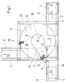
- FIG. 1 shows a plan view of a device for transferring conveyed goods 1 designed as workpiece carriers from a conveying conveyor track 2 to one of two continuing conveying tracks 3a, 3b.
- the conveyor tracks 2, 3a and 3b are designed as so-called double belt conveyors, which essentially consist of two elongated conveyor elements 4, which are designed parallel to one another and at a distance from one another and in each case as driven belt conveyors.
- the distance between the conveying elements 4 is selected so that the conveyed material 1, as seen in the conveying direction F, is carried on its sides by the conveying elements 4 and is additionally guided laterally via guide rails 5 guided parallel to the conveying elements 4.
- the conveyor elements 4 can also be designed as accumulation roller chain conveyors or in combination with belt conveyors, with at least one conveyor element 4 being driven.
- the device for transferring the conveyed goods 1 is arranged between the conveyor tracks 2, 3a and 3b and essentially consists of a drag plate 6 and a deflecting element 7.
- the circular drag plate 6 is mounted centrally on an axis of rotation 8 and can be driven in a predetermined direction of rotation D by a drive (not shown).
- the transport surfaces of the drag plate 6 and the conveying elements 4 are largely level and horizontally aligned.
- the feeding conveyor track 2 and the further conveyor track 3a are arranged in a common conveying direction F 1 and, viewed in this conveying direction, are aligned with one another.
- the drag plate 6 is arranged laterally projecting into the conveyor line formed by the conveyor tracks 2 and 3a in such a way that the conveyor elements 4 of the conveyor tracks 2 and 3a, which are on the side facing the axis of rotation 8 of the drag plate 6, are interrupted and in each case immediately in front of or end or start after the edge 9 of the drag plate 6.
- the conveying elements 4, which lie on the side of the conveying tracks 2 and 3a facing away from the axis of rotation 8 of the drag plate 6, on the other hand, are guided tangentially past the outer edge 9 of the drag plate 6 at a small distance.
- the conveying direction F 2 of the second further conveying track 3b is arranged at right angles to the conveying direction F 1 of the conveying tracks 2 and 3a.
- the conveyor track 3b is arranged with its conveyor elements 4 to the drag plate 6 in such a way that the outer conveyor element 4 facing away from the axis of rotation 8 of the drag plate 6 and thus outer is arranged with its guide rail 5 with a small tangential distance to the edge 9 of the drag plate 6.
- the inner conveying element 4 with its guide rail 5 is arranged offset inwards in relation to the axis of rotation 8 of the drag plate 6 in accordance with the width of the conveyed goods 1 and begins adjacent to the drag plate 6.
- the semicircular section is located in the area of the axis of rotation 8 of the deflecting element 7 and has a radius r originating in the axis of rotation 8, the amount of which is selected such that between the guide rails 5 of the conveyor tracks 2, 3a and 3b and the outer contour of the semicircular section 10 a distance remains that is greater than the width b of the conveyed material 1.
- the deflection element 7 tapers linearly until a width B is reached in the end region thereof, which is selected such that the end region of the deflection element 7 in the conveying direction F 1 , F 2 of the further conveying path 3a, 3b is seen with whose inner guide rail 5 is aligned.
- the deflection element 7 is driven from a first deflection position I, in which the material to be conveyed 1 is forwarded to the first further conveying path 3a, to a second deflection position II, in which the conveyed material 1 is forwarded to the second further conveying path 3b, via a frictional connection of the deflection element 7 with the rotationally driven drag plate 6.
- the frictional connection takes place via a sliding element, not shown, which is arranged on the underside of the deflection element 7 and rests on the surface of the drag plate 6.
- This drive connection can be interrupted in the deflection positions I, II by a holding element.
- the holding element is designed as a stop 12 which can be set, for example, by means of a pneumatic cylinder and which can be lifted vertically upward past the edge 9 of the drag plate 6 into the movement path of the deflecting element 7 to stop the deflecting element 7.
- the deflection element 7 is first stopped in the first deflection position I via the stop 12.
- the conveyed material 1 transported on the two conveying elements 4 of the conveying track 2 first reaches the edge 9 of the drag plate 6 with its right front side - seen in the conveying direction F 1 - and is pushed onto this.
- the conveyed goods 1 are pushed until the height of the axis of rotation 8 of the drag plate 6 has been reached, and the conveyed goods 1 are pushed over the frictional engagement with the drag plate 6 in the direction of the outer guide rail 5 of the conveyor track 2.
- the conveyed material 1 is taken along by the drag plate 6 in its direction of rotation D.
- the material to be conveyed 1 is guided down from the drag plate and thus pushed back onto the driven conveying elements 4 of the further conveyor track 3a.
- This process is favored by the fact that the deflecting element 7 has a width B in the end region of its arm-shaped section 11, which is chosen such that the last region of the deflecting element 7 is aligned with the inner guide rail 5 of the further conveying track 3a, as seen in the conveying direction F 1 .
- the material to be conveyed 1 is thus safely guided onto the further conveyor track 3a.
- the workpiece carriers to be conveyed (material to be conveyed 1) are laterally provided with guide rollers (not shown).
- the deflection element is stopped in the deflection position II.
- the conveyed material 1 conveyed up by the feeding conveyor track 2 behaves as previously described until it reaches the position in which the conveyed goods 1 are almost completely drawn onto the drag plate 6 from the outer conveying element 4 of the conveying track 2 and in the direction of rotation D in the direction of the continuing conveying track 3b is promoted.
- the material to be conveyed 1 is guided between the semicircular section 10 of the deflecting element 7 and the outer guide rail 5 of the further conveying path 3b.
- the conveyed goods 1 are again passed through the arm-shaped section 11 in the direction of the further conveying track 3b until the front edge of the conveyed goods 1 is gripped by the conveying elements 4 of the further conveying track 3b and thus the conveyed goods 1 can be pulled down from the drag plate 6.
- FIG. 2 shows a further exemplary embodiment of the device for transferring material to be conveyed, this being combined with two feeding conveyor tracks 2a and 2b and two further conveyor tracks 3a and 3b.
- one feeding and one further conveying path 2 , 3 are arranged in a common conveying direction F 1 and F 2 .
- the conveying directions F 1 and F 2 are oriented in opposite directions and parallel to one another.
- a drag plate 6 is arranged with a centrally mounted deflection element 7.
- the deflecting element 7 is double-arm-shaped and, seen in the top view of the drag plate 6, has an outer contour that is in the region of the axis of rotation 8 has a wider area 14 for guiding the material to be conveyed 1 on the drag plate 6 and, starting therefrom, two opposing and respectively tapering arm-shaped sections 11 for deflecting the material to be conveyed 1 are arranged.
- the width of the wider area 14 of the deflecting element 7 has been designed according to the same criteria as the radius r of the semicircular section 10 of the deflecting element 7 according to FIG.
- the arrangement of the conveyor track 2, 3 and the design of the double-armed deflecting element 7 are selected such that the deflecting element 7 in the single deflecting position I with its arm-shaped sections 11 in each case the material to be conveyed 1 from the conveying conveying tracks 2a, 2b to the further conveying tracks 3a, 3b with the same direction of conveyance F 1 , F 2 .
Landscapes
- Engineering & Computer Science (AREA)
- Mechanical Engineering (AREA)
- Attitude Control For Articles On Conveyors (AREA)
- Specific Conveyance Elements (AREA)
- Branching, Merging, And Special Transfer Between Conveyors (AREA)
- Framework For Endless Conveyors (AREA)
Applications Claiming Priority (2)
| Application Number | Priority Date | Filing Date | Title |
|---|---|---|---|
| DE19534500A DE19534500A1 (de) | 1995-09-05 | 1995-09-05 | Vorrichtung zum Überführen von Fördergut, insbesondere von Werkstückträgern |
| DE19534500 | 1995-09-05 |
Publications (3)
| Publication Number | Publication Date |
|---|---|
| EP0761575A2 true EP0761575A2 (fr) | 1997-03-12 |
| EP0761575A3 EP0761575A3 (fr) | 1997-03-26 |
| EP0761575B1 EP0761575B1 (fr) | 1999-06-02 |
Family
ID=7772430
Family Applications (1)
| Application Number | Title | Priority Date | Filing Date |
|---|---|---|---|
| EP96250176A Expired - Lifetime EP0761575B1 (fr) | 1995-09-05 | 1996-08-15 | Dispositif pour le transfert d'objets, notamment de porte-pièces |
Country Status (3)
| Country | Link |
|---|---|
| EP (1) | EP0761575B1 (fr) |
| AT (1) | ATE180745T1 (fr) |
| DE (2) | DE19534500A1 (fr) |
Cited By (1)
| Publication number | Priority date | Publication date | Assignee | Title |
|---|---|---|---|---|
| CN113135418A (zh) * | 2020-01-17 | 2021-07-20 | 江南大学 | 一种轨道分流系统 |
Families Citing this family (1)
| Publication number | Priority date | Publication date | Assignee | Title |
|---|---|---|---|---|
| WO2009035391A1 (fr) * | 2007-09-14 | 2009-03-19 | Flexlink Components Ab | Dispositif de deviation pour un système de convoyeur et procédé de deviation d'objets transportés le long d'un chemin de roulement de convoyage |
Family Cites Families (3)
| Publication number | Priority date | Publication date | Assignee | Title |
|---|---|---|---|---|
| DE1141590B (de) * | 1959-10-08 | 1962-12-20 | Haver & Boecker | Mehrwegfoerdereinrichtung fuer Stueckgueter |
| DE1969064U (de) * | 1967-07-15 | 1967-09-21 | Enzinger Union Werke Ag | Rollenbahn-umlenkvorrichtung. |
| DE4335196B4 (de) * | 1993-10-15 | 2005-06-09 | Altratec Montagesysteme Gmbh | Vorrichtung zum Ein- und Ausschleusen von Gegenständen bei Transportstrecken |
-
1995
- 1995-09-05 DE DE19534500A patent/DE19534500A1/de not_active Withdrawn
-
1996
- 1996-08-15 DE DE59602063T patent/DE59602063D1/de not_active Expired - Lifetime
- 1996-08-15 EP EP96250176A patent/EP0761575B1/fr not_active Expired - Lifetime
- 1996-08-15 AT AT96250176T patent/ATE180745T1/de active
Cited By (1)
| Publication number | Priority date | Publication date | Assignee | Title |
|---|---|---|---|---|
| CN113135418A (zh) * | 2020-01-17 | 2021-07-20 | 江南大学 | 一种轨道分流系统 |
Also Published As
| Publication number | Publication date |
|---|---|
| DE59602063D1 (de) | 1999-07-08 |
| EP0761575A3 (fr) | 1997-03-26 |
| DE19534500A1 (de) | 1997-03-06 |
| ATE180745T1 (de) | 1999-06-15 |
| EP0761575B1 (fr) | 1999-06-02 |
Similar Documents
| Publication | Publication Date | Title |
|---|---|---|
| EP2364936B1 (fr) | Dispositif et procédé de répartition d'articles à l'intérieur d'un flux d'articles | |
| DE69203528T2 (de) | Fördervorrichtung für Artikel. | |
| EP3652096B1 (fr) | Dispositif de stockage et de convoyeur et procédé de fonctionnement du dispositif de stockage et de convoyeur | |
| EP0641730B1 (fr) | Convoyeur de montage avec dispositif de transfert | |
| WO1988007968A1 (fr) | Dispositif de commande du trajet de deplacement d'objets | |
| DE4036214C2 (fr) | ||
| DE1177074B (de) | Treibvorrichtung fuer durch Schienen gefuehrte Wagen einer Foerderanlage | |
| EP2428471B1 (fr) | Convoyeur | |
| WO2008012214A1 (fr) | Distributeur pour articles | |
| DE4335196B4 (de) | Vorrichtung zum Ein- und Ausschleusen von Gegenständen bei Transportstrecken | |
| CH618939A5 (fr) | ||
| EP0469256B1 (fr) | Dispositif pour tansporter des marchandises en pièce | |
| DE10111808A1 (de) | Einrichtung zur Lagekorrektur eines Schlauchgurtförderers | |
| EP0761575B1 (fr) | Dispositif pour le transfert d'objets, notamment de porte-pièces | |
| DD236503A1 (de) | Foerdereinrichtung zur wahlweisen 180 hoch grad-drehung von buechern oder buchblocks | |
| EP1215142A1 (fr) | Dispositif de transport guidé sur rail et système de transport | |
| DE19624503A1 (de) | Hängefördereinrichtung | |
| DE29809909U1 (de) | Klinken-Sortierförderer | |
| DE4403594A1 (de) | Transportvorrichtung für textile Packungen | |
| DE4412276A1 (de) | Umlenkstation für Förderbahnen | |
| DE60222660T2 (de) | Vorrichtung für individuelle höhensortierung von platten | |
| CH461362A (de) | Förderanlage für Behälter oder Fördergutträger | |
| DE2243338B2 (de) | Gliederbandförderer | |
| DE2924259A1 (de) | In einer horizontalebene dreh- und arretierbare umlenkvorrichtung | |
| DE19534498A1 (de) | Vorrichtung zum Überführen von Fördergut, insbesondere von Werkstückträgern |
Legal Events
| Date | Code | Title | Description |
|---|---|---|---|
| PUAI | Public reference made under article 153(3) epc to a published international application that has entered the european phase |
Free format text: ORIGINAL CODE: 0009012 |
|
| PUAL | Search report despatched |
Free format text: ORIGINAL CODE: 0009013 |
|
| AK | Designated contracting states |
Kind code of ref document: A2 Designated state(s): AT CH DE GB IT LI NL |
|
| AK | Designated contracting states |
Kind code of ref document: A3 Designated state(s): AT CH DE GB IT LI NL |
|
| 17P | Request for examination filed |
Effective date: 19970526 |
|
| GRAG | Despatch of communication of intention to grant |
Free format text: ORIGINAL CODE: EPIDOS AGRA |
|
| GRAG | Despatch of communication of intention to grant |
Free format text: ORIGINAL CODE: EPIDOS AGRA |
|
| GRAH | Despatch of communication of intention to grant a patent |
Free format text: ORIGINAL CODE: EPIDOS IGRA |
|
| 17Q | First examination report despatched |
Effective date: 19981103 |
|
| GRAH | Despatch of communication of intention to grant a patent |
Free format text: ORIGINAL CODE: EPIDOS IGRA |
|
| GRAA | (expected) grant |
Free format text: ORIGINAL CODE: 0009210 |
|
| AK | Designated contracting states |
Kind code of ref document: B1 Designated state(s): AT CH DE GB IT LI NL |
|
| REF | Corresponds to: |
Ref document number: 180745 Country of ref document: AT Date of ref document: 19990615 Kind code of ref document: T |
|
| REG | Reference to a national code |
Ref country code: CH Ref legal event code: NV Representative=s name: E. BLUM & CO. PATENTANWAELTE Ref country code: CH Ref legal event code: EP |
|
| GBT | Gb: translation of ep patent filed (gb section 77(6)(a)/1977) |
Effective date: 19990603 |
|
| REF | Corresponds to: |
Ref document number: 59602063 Country of ref document: DE Date of ref document: 19990708 |
|
| ITF | It: translation for a ep patent filed | ||
| PLBE | No opposition filed within time limit |
Free format text: ORIGINAL CODE: 0009261 |
|
| STAA | Information on the status of an ep patent application or granted ep patent |
Free format text: STATUS: NO OPPOSITION FILED WITHIN TIME LIMIT |
|
| 26N | No opposition filed | ||
| REG | Reference to a national code |
Ref country code: GB Ref legal event code: IF02 |
|
| REG | Reference to a national code |
Ref country code: CH Ref legal event code: PFA Owner name: MANNESMANN AKTIENGESELLSCHAFT Free format text: MANNESMANN AKTIENGESELLSCHAFT#MANNESMANNUFER 2#40213 DUESSELDORF (DE) -TRANSFER TO- MANNESMANN AKTIENGESELLSCHAFT#MANNESMANNUFER 2#40213 DUESSELDORF (DE) |
|
| PGFP | Annual fee paid to national office [announced via postgrant information from national office to epo] |
Ref country code: NL Payment date: 20130805 Year of fee payment: 18 Ref country code: AT Payment date: 20130709 Year of fee payment: 18 |
|
| PGFP | Annual fee paid to national office [announced via postgrant information from national office to epo] |
Ref country code: GB Payment date: 20130814 Year of fee payment: 18 |
|
| PGFP | Annual fee paid to national office [announced via postgrant information from national office to epo] |
Ref country code: IT Payment date: 20130827 Year of fee payment: 18 |
|
| PGFP | Annual fee paid to national office [announced via postgrant information from national office to epo] |
Ref country code: DE Payment date: 20131021 Year of fee payment: 18 Ref country code: CH Payment date: 20131107 Year of fee payment: 18 |
|
| REG | Reference to a national code |
Ref country code: DE Ref legal event code: R119 Ref document number: 59602063 Country of ref document: DE |
|
| REG | Reference to a national code |
Ref country code: NL Ref legal event code: V1 Effective date: 20150301 |
|
| REG | Reference to a national code |
Ref country code: CH Ref legal event code: PL |
|
| REG | Reference to a national code |
Ref country code: AT Ref legal event code: MM01 Ref document number: 180745 Country of ref document: AT Kind code of ref document: T Effective date: 20140815 |
|
| GBPC | Gb: european patent ceased through non-payment of renewal fee |
Effective date: 20140815 |
|
| PG25 | Lapsed in a contracting state [announced via postgrant information from national office to epo] |
Ref country code: NL Free format text: LAPSE BECAUSE OF NON-PAYMENT OF DUE FEES Effective date: 20150301 Ref country code: LI Free format text: LAPSE BECAUSE OF NON-PAYMENT OF DUE FEES Effective date: 20140831 Ref country code: CH Free format text: LAPSE BECAUSE OF NON-PAYMENT OF DUE FEES Effective date: 20140831 Ref country code: IT Free format text: LAPSE BECAUSE OF NON-PAYMENT OF DUE FEES Effective date: 20140815 |
|
| REG | Reference to a national code |
Ref country code: DE Ref legal event code: R119 Ref document number: 59602063 Country of ref document: DE Effective date: 20150303 |
|
| PG25 | Lapsed in a contracting state [announced via postgrant information from national office to epo] |
Ref country code: AT Free format text: LAPSE BECAUSE OF NON-PAYMENT OF DUE FEES Effective date: 20140815 |
|
| PG25 | Lapsed in a contracting state [announced via postgrant information from national office to epo] |
Ref country code: DE Free format text: LAPSE BECAUSE OF NON-PAYMENT OF DUE FEES Effective date: 20150303 Ref country code: GB Free format text: LAPSE BECAUSE OF NON-PAYMENT OF DUE FEES Effective date: 20140815 |