EP0761982B1 - Module de ventilateur - Google Patents
Module de ventilateur Download PDFInfo
- Publication number
- EP0761982B1 EP0761982B1 EP96305622A EP96305622A EP0761982B1 EP 0761982 B1 EP0761982 B1 EP 0761982B1 EP 96305622 A EP96305622 A EP 96305622A EP 96305622 A EP96305622 A EP 96305622A EP 0761982 B1 EP0761982 B1 EP 0761982B1
- Authority
- EP
- European Patent Office
- Prior art keywords
- fan
- cooling apparatus
- motor
- heat exchanger
- heat exchangers
- Prior art date
- Legal status (The legal status is an assumption and is not a legal conclusion. Google has not performed a legal analysis and makes no representation as to the accuracy of the status listed.)
- Expired - Lifetime
Links
- 238000001816 cooling Methods 0.000 claims description 33
- 238000010276 construction Methods 0.000 description 2
- 238000004378 air conditioning Methods 0.000 description 1
- 230000004323 axial length Effects 0.000 description 1
- 238000002485 combustion reaction Methods 0.000 description 1
- 239000002826 coolant Substances 0.000 description 1
- 230000007423 decrease Effects 0.000 description 1
- 230000003247 decreasing effect Effects 0.000 description 1
- 238000009413 insulation Methods 0.000 description 1
- 238000012856 packing Methods 0.000 description 1
- 230000000717 retained effect Effects 0.000 description 1
- 238000011144 upstream manufacturing Methods 0.000 description 1
Images




Classifications
-
- B—PERFORMING OPERATIONS; TRANSPORTING
- B60—VEHICLES IN GENERAL
- B60K—ARRANGEMENT OR MOUNTING OF PROPULSION UNITS OR OF TRANSMISSIONS IN VEHICLES; ARRANGEMENT OR MOUNTING OF PLURAL DIVERSE PRIME-MOVERS IN VEHICLES; AUXILIARY DRIVES FOR VEHICLES; INSTRUMENTATION OR DASHBOARDS FOR VEHICLES; ARRANGEMENTS IN CONNECTION WITH COOLING, AIR INTAKE, GAS EXHAUST OR FUEL SUPPLY OF PROPULSION UNITS IN VEHICLES
- B60K11/00—Arrangement in connection with cooling of propulsion units
- B60K11/02—Arrangement in connection with cooling of propulsion units with liquid cooling
- B60K11/04—Arrangement or mounting of radiators, radiator shutters, or radiator blinds
-
- F—MECHANICAL ENGINEERING; LIGHTING; HEATING; WEAPONS; BLASTING
- F01—MACHINES OR ENGINES IN GENERAL; ENGINE PLANTS IN GENERAL; STEAM ENGINES
- F01P—COOLING OF MACHINES OR ENGINES IN GENERAL; COOLING OF INTERNAL-COMBUSTION ENGINES
- F01P3/00—Liquid cooling
- F01P3/18—Arrangements or mounting of liquid-to-air heat-exchangers
-
- F—MECHANICAL ENGINEERING; LIGHTING; HEATING; WEAPONS; BLASTING
- F04—POSITIVE - DISPLACEMENT MACHINES FOR LIQUIDS; PUMPS FOR LIQUIDS OR ELASTIC FLUIDS
- F04D—NON-POSITIVE-DISPLACEMENT PUMPS
- F04D29/00—Details, component parts, or accessories
- F04D29/58—Cooling; Heating; Diminishing heat transfer
- F04D29/582—Cooling; Heating; Diminishing heat transfer specially adapted for elastic fluid pumps
-
- F—MECHANICAL ENGINEERING; LIGHTING; HEATING; WEAPONS; BLASTING
- F28—HEAT EXCHANGE IN GENERAL
- F28F—DETAILS OF HEAT-EXCHANGE AND HEAT-TRANSFER APPARATUS, OF GENERAL APPLICATION
- F28F9/00—Casings; Header boxes; Auxiliary supports for elements; Auxiliary members within casings
- F28F9/001—Casings in the form of plate-like arrangements; Frames enclosing a heat exchange core
- F28F9/002—Casings in the form of plate-like arrangements; Frames enclosing a heat exchange core with fastening means for other structures
Definitions
- the present invention relates to a cooling apparatus and more specifically but not exclusively to such apparatus for cooling heat engines used in particular in automobile vehicles. More precisely, it proposes a new arrangement of the motor fan group relative to two heat exchangers such as the radiator and the condenser.
- the complete cooling module equipping many vehicles comprises a radiator, a condenser, a fan, a motor and a shroud.
- This shroud has a double function. On the one hand it ensures better guidance of the air across the exchangers and, on the other hand, it enables the fan ventilator group to be fixed and held. However, it forms too large a fraction of the volume relative to the total volume of the module. Equally it makes a significant contribution to the total weight and cost of the module.
- One aim of the present invention is to provide a cooling apparatus so as not to comprise a shroud but at the same time without in any way decreasing the fan performance.
- the fan is mounted between the condenser and the radiator, the motor being mounted directly on the condenser. In this manner a great reduction in the weight, the cost and the size of the module may be achieved.
- FR-A-936 794 discloses a heat exchanging arrangement wherein two or more heat exchangers are disposed in series.
- US-A-3,203,499 discloses a cooling arrangement for supercharged engines and more particularly relates to an intercooler and radiator arrangement for an internal combustion engine.
- US-A-4,351,162 discloses an apparatus for cooling a vehicle engine and for air conditioning the vehicle which includes a planar, liquid-coolant radiator parallel with and spaced apart from a planar condenser, and a fan mounted between the radiator and the condenser with an electric motor mounted within the fan hub.
- a cooling apparatus comprising a first heat exchanger and a second heat exchanger, the two heat exchangers being disposed such that each has at least a portion in face-to-face relationship with the other, the apparatus further comprising a fan and a ring member circumferentially enclosing the periphery of the fan, the ring member being secured to at least one of the two heat exchangers and the fan being disposed between the facing portions of the heat exchangers, further comprising an electric motor rotating the fan, the electric motor having a shaft member, wherein one of the heat exchangers defines a passageway for the shaft member and the shaft member extends from the electric motor on one side of said heat exchanger to the fan on the other side of said heat exchanger whereby the fan is secured to the shaft member, characterised in that the electric motor is directly mounted on one of the first and second heat exchangers.
- the first heat exchanger is a radiator and the second heat exchanger is a condenser.
- the condenser consists of plural condenser tubes and the motor shaft passes between the condenser tubes via a through hole.
- the ring is secured to the radiator.
- the motor is directly mounted on the condenser.
- the first and second heat exchanger are secured to one another by fixing pads.
- a cooling module comprising a radiator, a condenser, two motors, two fans and two non rotating rings each extending about the periphery of a respective fan wherein the two fans are mounted between the condenser and the radiator.
- each motor has a respective shaft, the two motor shafts pass between the tubes of the condenser bundle through two through holes.
- the two rings are secured to the radiator.
- the motors are directly mounted on the condenser.
- a cooling apparatus comprising a first heat exchanger and a second heat exchanger, the two heat exchangers being disposed such that each has at least a portion in face-to-face relationship with the other, the arrangement further comprising a plurality of fans and a corresponding plurality of ring members, each ring member circumferentially enclosing the periphery of a respective one of the fans, the ring members being secured to at least one of the two heat exchangers and the fans being disposed between facing portions of the heat exchangers.
- the or each fan comprises a hub portion having secured thereto a first plurality of first blades extending therefrom radially outwardly to a first circumferentially-extending blade support member, and a second plurality of second blades extending radially outwardly from the first support member.
- an auxiliary fan is disposed on the outer face portion of one of the first and second heat exchangers.
- the electric motor is a brushless d.c. motor.
- FIG. 1 to 7 show embodiments in accordance with the present invention.
- Figures 8 to 10 show arrangements not in accordance with the present invention, but which are retained in the present application for reasons of clarity and completeness:
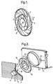
- Figure 1 shows an isometric view of an axial flow fan suitable for use with the present invention
- Figure 2 shows a first embodiment of a cooling apparatus in accordance with the present invention, showing an axial flow fan disposed between a condenser and a radiator, a non-rotating ring being secured to the radiator.
- Figure 3 shows a cooling apparatus similar to that of Figure 2, but having two fans disposed side by side between the condenser and radiator.
- Figure 4 shows a cooling apparatus having the fan disposed between a condenser and a radiator, with an auxiliary fan disposed on the outer face of the condenser.
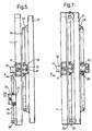
- Figure 5 shows a transverse cross-section through the arrangement of Figure 4.
- Figure 6 shows an arrangement similar to Figure 4, but with the auxiliary fan secured to the outer face of the radiator.
- Figure 7 shows a transverse cross-section through the arrangement of Figure 6.
- Figure 8 shows an axial cross-section through a fan showing an integral electric motor.
- Figure 9 shows a more detailed view of the construction of the motor of Figure 8.
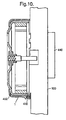
- Figure 10 shows a motor having remote commutating circuitry.
- an axial flow fan has a hub member (1) having an external periphery which supports a first plurality of radially-extending first blades (2). At the tip region of the first blades, the first blades are connected together by a first circumferentially-extending blade support member (3) which also forms a root-support member for a second plurality of second blades (4) are, in turn, supported at their tip regions by a second blade-tip support member (5) which is disposed concentrally with the fan axis and the first blade tip support member (3).
- the hub member (1) has a generally planar front face portion and a centrally-disposed aperture (22) for a fan drive shaft.
- the above-described fan has a reduced axial extent. At the same time, this fan has good air-moving properties because it provides air moving ability over a large proportion of the fan radial extent. It will be realised that these features make the fan described with respect to Figure 1 useful in the context of the present invention.
- a major feature is the positioning of the fan betwen two heat exchangers, such as a condenser and a radiator.
- a consequence of this arrangement is the ability to eliminate the shroud and this results in a large reduction in the space utilised beneath the bonnet of an associated vehicle and also a reduction in the weight and cost of the cooling apparatus.
- a motor (12) is secured to a condenser (11).
- the motor has three fixing pads (13) in the region of a front motor flange (14).
- Three counterpart fixing pads (15) are brazed to the front face of the condenser.
- a hole (16) is provided through the condensor between the tubes, for example through condensor pins, to allow the motor shaft (17) to pass through. After the motor shaft (17) has been passed through the hole (16) in the condenser, the motor is secured to the condenser by fixing pads (13) and (15).
- a fan (18) has an insert (19) in its centre and the shaft is fixed in this insert.
- a fixed ring (20) is secured to the front face of a radiator (21). This fixed ring has two fixing lugs (22) which are riveted to two further fixing lugs (23) of the radiator.
- the radiator and condenser are secured to one another indirectly by means of four fixing lugs (24).
- the module comprises only one motor and consequently only one fan.
- the module comprises two motors and two fans, the principle being otherwise similar - see Fig 3.
- the motors (12,12') have three (or four) fixing pads and are fixed directly on the front (in relation to the direction of the air flow) face of the condenser (11).
- Two holes (16,16') are provided between the tubes of the condenser, eg through fins of the condensor.
- the two motor shafts (17,17') pass through the condenser through the two holes (14) and (15).
- the two fans (18,18'). are fixed on the two motor shafts indirectly by means of two inserts mounted at the centre of the fans.
- Two fan-rotating rings (20,20') are fixed on the front face of the radiator (21).
- the main rings may be secured to the condenser instead of to the radiator.
- a fan disposed between the radiator and the condenser is not sufficient to produce the desired air flow. It is then possible to site a further fan and a further motor to provide additional flow, the further fan being in front of the condenser rather than between the heat exchangers. So far as the first fan is concerned, this is always mounted in the "fan-between" configuration, whereby the first fan is located between the two exchangers.
- the second or further fan is a so-called pusher fan and is located in front of the condenser upstream in the flow of air.
- a principal motor (12) for the first fan (18) is mounted on the condenser (11) at the centre of the latter.
- a hole (16) is provided, in the centre, through the condenser body, between two pipes of the latter.
- the motor shaft (17) passes through the condenser through this hole and is fixed to the first fan (18) by an insert (19) located at the centre of the hub (32) of the fan.
- a fixed ring (20) is mounted on the radiator (21). To secure the ring to the radiator, two fixing lugs may be used which make it possible to screw the collar to the radiator.
- a second motor (25) is mounted on the front face (in relation to the air flow direction A) of the condenser. This second motor comprises three motor fixing lugs (26) ⁇ in the region of a rear flange (27).
- the said three motor fixing lugs together with three fixing lugs brazed on the condenser, makes it possible to fix the motor on the front face of the condenser.
- a second fan (30) is mounted on a shaft (31) of the second motor. Then, because in this configuration the relative position of the motor is reversed, the hub (33) of the auxiliary fan is also reversed. To avoid the blades of the second fan (30) being spaced too far from the condenser, the axial length of the hub (33) is increased so as to bring the fan blades close to the condenser.
- a second ring (34) is secured to the front face of the condenser thus enabling better guidance of the air flow which the auxiliary fan generates.
- This arrangement is especially suitable for low or medium power auxiliary motors (from about 100 to 200 watts).
- a further embodiment provides a second motor and fan secured to the radiator. This is useful where a fan disposed between the two heat exchangers does not by itself provide a sufficient flow rate for satisfactory cooling.
- the fan is a puller fan and is positioned on the rear face of the radiator (in relation to the air flow).
- a first motor (12) is mounted on a condenser (11) at the centre of the latter.
- a hole (16) is provided, in the centre, through the condenser body, between two pipes of the latter.
- a motor shaft (17) passes through the condenser through this hole and is fixed to a first fan (18) via an insert (19) located at the centre of the hub of the first fan.
- a ring (20) is mounted on a radiator (21). To fix the ring, two fixing lugs are used which make it possible to screw the ring to the radiator.
- a second auxiliary motor (25) is mounted on the rear (with respect to the airflow direction A) face of the radiator, the rear flange of the motor being attached to the latter.
- Three motor fixing lugs (26) make it possible to fix the motor on the radiator.
- a ring (34) is mounted on the rear face of the radiator.
- the said ring comprises two fixing lugs enabling it to be screwed directly to the radiator.
- Fixing lugs (35) enable the radiator and condenser to be secured together.
- this arrangement is especially suitable for low power auxiliary motors (from about 60 to 120 watts).
- the fan motor for the or each fan disposed between the two heat exchanger has a shaft which passes through an aperture through one of the heat exchangers.
- An electronically-commutated or brushless d.c. motor may be embodied as a switched-reluctance motor, but, in a more preferred embodiment, the motor is a permanent magnet brushless motor.
- the fan hub (1) has an internal cup-shaped member (400) which carries permanent magnets (401,402).
- the cup-shaped member (400) which may be integrally formed with the hub, thus providing improved packing density, forms the rotor of an electronically-commutated motor.
- the motor further consists of a stator which has core members (410,411) each carrying a respective coil (420,421).
- the core members and the cores are secured to a base plate which is then secured to a corresponding face portion of the condenser.
- the base plate (430) may include the necessary electronic commutating circuitry for switching a direct current supply sequentially to the coils (420,421) to create a rotating magnetic field, thus applying torque to the cup-shaped rotor member (400) for rotating the fan hub (1) and hence the blades.
- the rotating field may be controlled depending on the position of the rotor, to ensure synchronism between the stator and rotor fields.
- Figure 9 shows a more detailed construction of the rotor and stator described above.
- the base plate member (430) has a central boss portion (431) which extends axially of the associated fan, and which supports a shaft member (432) via first and second bearings (433,434).
- the first bearing (433) is a ball bearing and the second bearing (434) is a sleeve bearing.
- the base plate member (430) supports a circuit module (440). It will be seen therefore that when the fan and base plate are mounted to a face portion of a heat exchanger, the circuit module (440) will be on the same side of the heat exchanger as the fan.
- a heat exchanger (500) supports a base plate (430) on one surface thereof, and on the opposing surface there is disposed a circuit module (440).
- This arrangement is advantageous in a vehicle application where the heat exchanger (500) is a vehicle radiator or the like, and where the circuit module (440) is better cooled by being disposed on the side of the radiator directed towards an incoming air flow. It will of course, be realised that the circuit module could instead be located remote from the radiator or other heat exchanger, for example secure to the vehicle body work itself. However, this involves complications when mounting the arrangement to provide the necessary paths for the connecting wires.
- the overall insulation size is considerably reduced with respect to the classical cooling arrangement, in which separate structures are required to support the fan, the condenser and the radiator.
- the fan itself is substantially shielded all round, which gives rise to a well-protected fan. It will be clear to one skilled in the art that the fan which is so shielded will be inaccessible to one working under the bonnet of a vehicle, and this will preclude accidents due to entanglement with the rotating fan. Likewise, damage to the fan itself is highly unlikely in this arrangement.
Landscapes
- Engineering & Computer Science (AREA)
- Mechanical Engineering (AREA)
- General Engineering & Computer Science (AREA)
- Chemical & Material Sciences (AREA)
- Combustion & Propulsion (AREA)
- Physics & Mathematics (AREA)
- Thermal Sciences (AREA)
- Transportation (AREA)
- Air-Conditioning For Vehicles (AREA)
Claims (15)
- Appareil de refroidissement comprenant un premier échangeur thermique (21) et un deuxième échangeur thermique (11), les deux échangeurs thermiques étant disposés de telle façon que chacun a au moins une partie dans une relation de face à face avec l'autre, l'appareil comprenant en outre un ventilateur (18) et un élément circulaire (20) enfermant de façon circonférentielle la périphérie du ventilateur (18), l'élément circulaire (20) étant fixé à au moins un des deux échangeurs thermiques (11, 21) et le ventilateur (18) étant disposé entre les parties se faisant face des échangeurs thermiques (11, 21), comprenant par ailleurs un moteur électrique (12) faisant tourner le ventilateur (18), le moteur électrique (12) ayant un élément arbre (17), dans lequel un des échangeurs thermiques (11, 21) définit un passage (16) pour l'élément arbre (17) et l'élément arbre (17) s'étend à partir du moteur électrique (12) sur un côté dudit échangeur thermique (11, 21) jusqu'au ventilateur (18) sur l'autre côté dudit échangeur thermique (11, 21) ce par quoi le ventilateur (18) est fixé à l'élément arbre (17), caractérisé en ce que le moteur électrique est monté directement sur le premier ou le deuxième des deux échangeurs thermiques (11, 21).
- Appareil de refroidissement selon la revendication 1, dans lequel le premier échangeur thermique est un radiateur (21) et le deuxième échangeur thermique est un condenseur (11).
- Appareil de refroidissement selon l'une quelconque des revendications précédentes, dans lequel le premier (21) et le deuxième (11) échangeurs thermiques sont fixés l'un à l'autre.
- Appareil de refroidissement selon l'une quelconque des revendications précédentes, dans lequel le ventilateur (18) comprend une partie moyeu (1) sur laquelle est fixée une première pluralité de premières pales (2) s'étendant a partir de là vers l'extérieur dans le sens radial jusqu'à un premier élément de support de pale s'étendant dans le sens circonférentiel (3), et une deuxième pluralité de deuxièmes pales (4) s'étendant dans le sens radial vers l'extérieur à partir du premier élément de support (3).
- Appareil de refroidissement selon l'une quelconque des revendications précédentes, dans lequel un ventilateur auxiliaire (30) est disposé sur la partie de face extérieure du premier (21) ou du deuxième (11) échangeurs thermiques.
- Appareil de refroidissement selon l'une quelconque des revendications précédentes, dans lequel ledit moteur électrique (12) est un moteur à courant continu (c.c.) sans collecteur.
- Appareil de refroidissement selon la revendication 6, dans lequel le moteur c.c. sans collecteur (12) comprend un circuit électronique de commutation (440).
- Appareil de refroidissement selon la revendication 7, dans lequel ledit circuit de commutation (440) est disposé dans l'écoulement d'air entrant d'un échangeur thermique associé (500).
- Appareil de refroidissement selon l'une quelconque des revendications précédentes, dans lequel l'agencement comprend un ou plusieurs moteurs électriques (12'), ventilateurs (18') et éléments circulaires correspondants (20') supplémentaires, chaque élément circulaire (20, 20') enfermant de façon circonférentielle la périphérie de l'un des ventilateurs respectifs (18, 18'), les éléments circulaires (20, 20') étant fixés à au moins un des deux échangeurs thermiques (11, 21) et les ventilateurs (18, 18') étant disposés entre les parties se faisant face des échangeurs thermiques (11, 21).
- Appareil de refroidissement selon la revendication 9, dans lequel chaque moteur d'entraínement de ventilateur supplémentaire (12') est monté directement sur l'un des premier et deuxième échangeurs thermiques (21, 11).
- Appareil de refroidissement selon la revendication 9 ou la revendication 10, dans lequel chaque ventilateur (18') comprend une partie moyeu (1) sur laquelle est fixée une première pluralité de premières pales (2) s'étendant à partir de là vers l'extérieur dans le sens radial jusqu'à un premier élément de support de pale s'étendant dans le sens circonférentiel (3), et une deuxième pluralité de deuxièmes pales (4) s'étendant dans le sens radial vers l'extérieur à partir du premier élément de support (3).
- Appareil de refroidissement selon l'une quelconque des revendications 9 à 11, dans lequel chaque moteur électrique (12') a un élément arbre (17), un des échangeurs thermiques (21, 11) définissant un passage (16) pour chaque élément arbre (17) et chaque élément arbre (17) s'étendant vers l'espace entre les deux échangeurs thermiques (21, 11) ce par quoi un ventilateur (18') est fixé à chaque élément arbre (17).
- Appareil de refroidissement selon l'une quelconque des revendications 9 à 12, dans lequel ledit moteur électrique (12') est un moteur c.c. sans collecteur.
- Appareil de refroidissement selon la revendication 13, dans lequel chaque moteur c.c. sans collecteur (12') comprend un circuit électronique de commutation (440).
- Appareil de refroidissement selon la revendication 14, dans lequel ledit circuit de commutation (440) est disposé dans l'écoulement d'air entrant d'un échangeur thermique associé (500).
Applications Claiming Priority (2)
| Application Number | Priority Date | Filing Date | Title |
|---|---|---|---|
| US511037 | 1983-07-05 | ||
| US08/511,037 US5771961A (en) | 1995-08-03 | 1995-08-03 | Fan module |
Publications (2)
| Publication Number | Publication Date |
|---|---|
| EP0761982A1 EP0761982A1 (fr) | 1997-03-12 |
| EP0761982B1 true EP0761982B1 (fr) | 2003-01-15 |
Family
ID=24033202
Family Applications (1)
| Application Number | Title | Priority Date | Filing Date |
|---|---|---|---|
| EP96305622A Expired - Lifetime EP0761982B1 (fr) | 1995-08-03 | 1996-07-31 | Module de ventilateur |
Country Status (3)
| Country | Link |
|---|---|
| US (1) | US5771961A (fr) |
| EP (1) | EP0761982B1 (fr) |
| DE (1) | DE69625758T2 (fr) |
Cited By (3)
| Publication number | Priority date | Publication date | Assignee | Title |
|---|---|---|---|---|
| DE102008043459A1 (de) | 2008-11-04 | 2010-05-06 | Brose Fahrzeugteile GmbH & Co. Kommanditgesellschaft, Würzburg | Axiallüfter und Flügelrad eines Axiallüfters |
| DE102008043460A1 (de) | 2008-11-04 | 2010-05-06 | Brose Fahrzeugteile GmbH & Co. Kommanditgesellschaft, Würzburg | Axiallüfter und Flügelrad eines Axiallüfters |
| DE102021121747A1 (de) | 2021-08-23 | 2023-02-23 | Klaus-Dieter Pfeffer | Lüfterrad und Lüfter mit demselben |
Families Citing this family (40)
| Publication number | Priority date | Publication date | Assignee | Title |
|---|---|---|---|---|
| FR2766912B1 (fr) * | 1997-08-01 | 1999-10-22 | Valeo Thermique Moteur Sa | Procede de fixation d'un accessoire a un echangeur de chaleur |
| FR2769360B1 (fr) * | 1997-10-02 | 1999-12-24 | Valeo Thermique Moteur Sa | Dispositif de fixation d'un accessoire a un echangeur de chaleur |
| GB2332046A (en) * | 1997-12-03 | 1999-06-09 | Concentric Pumps Ltd | I.C engine cooling system |
| JP3033735B2 (ja) * | 1998-06-17 | 2000-04-17 | 日本電気株式会社 | 密閉型筐体 |
| FR2785979B1 (fr) * | 1998-11-17 | 2001-01-26 | Ecia Equip Composants Ind Auto | Agencement d'un moteur de ventilateur sur un echangeur de chaleur et bloc avant pour vehicule automobile muni de cet agencement |
| US6155335A (en) * | 1999-04-26 | 2000-12-05 | Delphi Technologies, Inc. | Vehicle fan shroud and component cooling module |
| US6208052B1 (en) | 1999-08-18 | 2001-03-27 | Siemens Canada Limited | Cooling module for an electronically controlled engine |
| US6309178B1 (en) * | 1999-09-22 | 2001-10-30 | Young S. Kim | Downstream guiding device for fan-radiator cooling system |
| US7238004B2 (en) * | 1999-11-25 | 2007-07-03 | Delta Electronics, Inc. | Serial fan with a plurality of rotor vanes |
| US6491502B2 (en) * | 2000-08-23 | 2002-12-10 | Siemens Canada Limited | Center mounted fan module with even airflow distribution features |
| DE10109621B4 (de) * | 2001-02-28 | 2006-07-06 | Delta Electronics, Inc. | Serieller Lüfter |
| US6653755B2 (en) * | 2001-05-30 | 2003-11-25 | Intel Corporation | Radial air flow fan assembly having stator fins surrounding rotor blades |
| JP2004036569A (ja) * | 2002-07-05 | 2004-02-05 | Minebea Co Ltd | 直列送風装置 |
| US7406835B2 (en) * | 2005-05-10 | 2008-08-05 | Emp Advanced Development, Llc | Cooling system and method for cooling a heat producing system |
| DE102005039090A1 (de) * | 2005-08-06 | 2007-02-08 | Behr Gmbh & Co. Kg | Montageträgersystem |
| EP1934485B1 (fr) * | 2005-10-12 | 2011-05-04 | Brose Fahrzeugteile GmbH & Co. KG, Würzburg | Module ventilateur de radiateur pour un vehicule a moteur |
| US20080247879A1 (en) * | 2005-10-12 | 2008-10-09 | Pietro De Filippis | Cooling Fan Module for a Motor Vehicle |
| DE102005049261B3 (de) | 2005-10-14 | 2007-03-29 | Siemens Ag | Kühlerlüfter für ein Kraftfahrzeug |
| EP2011977A1 (fr) * | 2006-04-04 | 2009-01-07 | Calsonic Kansei Corporation | Échangeur de chaleur pour véhicule |
| US8827224B2 (en) * | 2007-05-15 | 2014-09-09 | Dana Canada Corporation | Mounting bracket for heat exchanger core face |
| US20090211287A1 (en) * | 2008-02-25 | 2009-08-27 | Carrier Corporation | Modular condenser fan assembly |
| JP5199849B2 (ja) * | 2008-12-05 | 2013-05-15 | 三菱重工業株式会社 | 車両用熱交換モジュールおよびこれを備えた車両 |
| US20100218916A1 (en) * | 2009-02-27 | 2010-09-02 | Ford Global Technolgies, Llc | Plug-in hybrid electric vehicle secondary cooling system |
| CN102097893B (zh) * | 2009-12-15 | 2015-03-11 | 光阳工业股份有限公司 | 交流发电机飞轮的冷却构造 |
| DE102012206496A1 (de) * | 2012-04-19 | 2013-10-24 | Robert Bosch Gmbh | Elektrische Maschine mit einem Lüfterrad mit hoher Schaufelanzahl |
| US9103599B2 (en) * | 2012-08-30 | 2015-08-11 | Wei-Ching Lee | Flake and method for reducing temperature of waste heat discharged from air conditioner |
| USD743517S1 (en) * | 2013-06-17 | 2015-11-17 | Richard Booth Platt | Heat exchanger |
| US9212598B2 (en) * | 2013-06-17 | 2015-12-15 | Richard Booth Platt | Modular cooling unit for automotive vehicle |
| DE102013018740A1 (de) | 2013-11-07 | 2015-05-07 | Daimler Ag | Kühlvorrichtung für eine Verbrennungskraftmaschine |
| KR102149733B1 (ko) * | 2013-12-27 | 2020-08-31 | 삼성전자주식회사 | 자기냉각장치 및 이를 갖춘 자기냉각시스템 |
| JP6845766B2 (ja) * | 2017-08-22 | 2021-03-24 | 川崎重工業株式会社 | 鞍乗型車両及びラジエータ導風装置 |
| DE102018214782A1 (de) * | 2018-08-30 | 2020-03-05 | Brose Fahrzeugteile GmbH & Co. Kommanditgesellschaft, Würzburg | Lüfterzarge eines Kraftfahrzeugs |
| USD891327S1 (en) * | 2018-10-24 | 2020-07-28 | Specialty Auto Parts U.S.A., Inc. | Decorative shroud for a coolant radiator with flush-fit fan |
| TWI695669B (zh) * | 2019-06-21 | 2020-06-01 | 仁寶電腦工業股份有限公司 | 散熱模組 |
| US11560826B2 (en) * | 2020-08-15 | 2023-01-24 | Kubota Corporation | Working machine |
| US11655824B2 (en) | 2020-08-26 | 2023-05-23 | Robert Bosch Llc | Fan module including coaxial counter rotating fans |
| US11988422B2 (en) * | 2021-04-28 | 2024-05-21 | Carrier Corporation | Microchannel heat exchanger drain |
| US11951797B2 (en) * | 2021-06-03 | 2024-04-09 | Brose Fahrzeugteile SE & Co. Kommanditgesellschaft, Würzburg | Cooling pack assembly |
| DE102021118148A1 (de) | 2021-07-14 | 2023-01-19 | Ebm-Papst Mulfingen Gmbh & Co. Kg | Kühlvorrichtung mit zwei stirnseitigen voneinander getrennt anströmbaren Teilflächen |
| CN116085305B (zh) * | 2023-02-16 | 2025-06-06 | 深圳罗米智能创新有限公司 | 一种高压风轮 |
Family Cites Families (16)
| Publication number | Priority date | Publication date | Assignee | Title |
|---|---|---|---|---|
| DE205050C (fr) * | ||||
| US1612110A (en) * | 1924-01-08 | 1926-12-28 | Firm Edmund Kletzsch | Screw propeller |
| FR936794A (fr) * | 1944-12-28 | 1948-07-29 | Svenska Flaektfabriken Ab | Dispositif ventilateur |
| US2738957A (en) * | 1955-05-02 | 1956-03-20 | Nathaniel B Wales | Radiator heat-transfer accelerator |
| US3061277A (en) * | 1958-10-16 | 1962-10-30 | John E Mitchell Company Inc | Air conditioner blower control |
| US3203499A (en) * | 1962-06-08 | 1965-08-31 | Caterpillar Tractor Co | Cooling arrangement for supercharged engines |
| US3275071A (en) * | 1964-05-08 | 1966-09-27 | Peerless Of America | Heat exchangers |
| US3938587A (en) * | 1975-01-06 | 1976-02-17 | Hayden Trans-Cooler, Inc. | Cooler fastening system |
| FR2373697A1 (fr) * | 1976-12-13 | 1978-07-07 | Ferodo Sa | Groupe moto-ventilateur a moteur refroidi |
| US4351162A (en) * | 1980-10-01 | 1982-09-28 | Wallace Murray Corp. | Apparatus for engine cooling and vehicle air conditioning |
| JPS58210487A (ja) * | 1982-05-31 | 1983-12-07 | Mitsubishi Electric Corp | 熱交換装置 |
| DE3702267A1 (de) * | 1987-01-27 | 1988-08-04 | Bayerische Motoren Werke Ag | Anordnung von zumindest zwei luft-fluessigkeits-waermetauschern an kraftfahrzeugen |
| US4979584A (en) * | 1989-05-25 | 1990-12-25 | Siemens-Bendix Automotive Electronics Limited | Automotive vehicle engine bay ventilation |
| US5097891A (en) * | 1990-10-05 | 1992-03-24 | Paccar Inc. | Parallel core charge air cooler |
| JP3191385B2 (ja) * | 1991-07-12 | 2001-07-23 | 株式会社デンソー | 凝縮器の取り付け装置 |
| DE9114734U1 (de) * | 1991-11-27 | 1992-01-23 | Behr GmbH & Co, 7000 Stuttgart | Halterung für den Kühler eines Kraftfahrzeugmotors |
-
1995
- 1995-08-03 US US08/511,037 patent/US5771961A/en not_active Expired - Fee Related
-
1996
- 1996-07-31 EP EP96305622A patent/EP0761982B1/fr not_active Expired - Lifetime
- 1996-07-31 DE DE69625758T patent/DE69625758T2/de not_active Expired - Fee Related
Cited By (5)
| Publication number | Priority date | Publication date | Assignee | Title |
|---|---|---|---|---|
| DE102008043459A1 (de) | 2008-11-04 | 2010-05-06 | Brose Fahrzeugteile GmbH & Co. Kommanditgesellschaft, Würzburg | Axiallüfter und Flügelrad eines Axiallüfters |
| DE102008043460A1 (de) | 2008-11-04 | 2010-05-06 | Brose Fahrzeugteile GmbH & Co. Kommanditgesellschaft, Würzburg | Axiallüfter und Flügelrad eines Axiallüfters |
| DE102021121747A1 (de) | 2021-08-23 | 2023-02-23 | Klaus-Dieter Pfeffer | Lüfterrad und Lüfter mit demselben |
| WO2023025352A1 (fr) | 2021-08-23 | 2023-03-02 | Pfeffer Klaus Dieter | Roue de ventilateur et ventilateur doté de ladite roue de ventilateur |
| DE102021121747B4 (de) | 2021-08-23 | 2023-09-14 | Klaus-Dieter Pfeffer | Lüfterrad und Lüfter mit demselben |
Also Published As
| Publication number | Publication date |
|---|---|
| US5771961A (en) | 1998-06-30 |
| DE69625758D1 (de) | 2003-02-20 |
| EP0761982A1 (fr) | 1997-03-12 |
| DE69625758T2 (de) | 2003-10-16 |
Similar Documents
| Publication | Publication Date | Title |
|---|---|---|
| EP0761982B1 (fr) | Module de ventilateur | |
| US6129524A (en) | Motor-driven centrifugal air compressor with axial airflow | |
| US8251674B1 (en) | Brushless cooling fan | |
| JP4743786B2 (ja) | コンパクト高出力オルタネータ | |
| AU2018302693B2 (en) | In-wheel electric motor provided with a cooling system | |
| JP4187606B2 (ja) | 電動機 | |
| JP7180925B2 (ja) | 軸方向磁束モータウォータポンプ | |
| US20140354090A1 (en) | Electric machine with liquid cooled housing and end cap | |
| KR20160014055A (ko) | 유체 냉각형 하우징을 구비한 전기 기계 | |
| JP2012507252A (ja) | モータの空気流冷却 | |
| US20210288553A1 (en) | Motor arrangement | |
| JP7756132B2 (ja) | アウタロータ型モータ | |
| US20040084977A1 (en) | Permanent magnet generator with an integral cooling system | |
| JPH09252563A (ja) | 制御装置一体型モータ | |
| US3020427A (en) | Ventilation of dynamoelectric machine drive units | |
| KR19990068855A (ko) | 내연기관용모터보조식터보냉각시스템 | |
| US7554228B2 (en) | Cooling fan with an outer rotor motor | |
| JP3294497B2 (ja) | 交流発電機 | |
| CN113853728A (zh) | 电机 | |
| JP2932900B2 (ja) | 車両用電動ファン装置 | |
| JPH07170695A (ja) | 車両用交流発電機 | |
| US6841901B2 (en) | Electric machine | |
| JP2003230253A (ja) | 回転電機 | |
| US11025134B2 (en) | Motor and ducted fan having heat radiation portions for cooling magnets | |
| US11038390B2 (en) | Electrical machine apparatus having a conduit with a particular arrangement for an inlet and outlet |
Legal Events
| Date | Code | Title | Description |
|---|---|---|---|
| PUAI | Public reference made under article 153(3) epc to a published international application that has entered the european phase |
Free format text: ORIGINAL CODE: 0009012 |
|
| AK | Designated contracting states |
Kind code of ref document: A1 Designated state(s): DE ES FR GB IT |
|
| 17P | Request for examination filed |
Effective date: 19970816 |
|
| 17Q | First examination report despatched |
Effective date: 20010528 |
|
| GRAG | Despatch of communication of intention to grant |
Free format text: ORIGINAL CODE: EPIDOS AGRA |
|
| GRAG | Despatch of communication of intention to grant |
Free format text: ORIGINAL CODE: EPIDOS AGRA |
|
| GRAH | Despatch of communication of intention to grant a patent |
Free format text: ORIGINAL CODE: EPIDOS IGRA |
|
| GRAH | Despatch of communication of intention to grant a patent |
Free format text: ORIGINAL CODE: EPIDOS IGRA |
|
| GRAA | (expected) grant |
Free format text: ORIGINAL CODE: 0009210 |
|
| AK | Designated contracting states |
Kind code of ref document: B1 Designated state(s): DE ES FR GB IT |
|
| PG25 | Lapsed in a contracting state [announced via postgrant information from national office to epo] |
Ref country code: IT Free format text: LAPSE BECAUSE OF FAILURE TO SUBMIT A TRANSLATION OF THE DESCRIPTION OR TO PAY THE FEE WITHIN THE PRE;WARNING: LAPSES OF ITALIAN PATENTS WITH EFFECTIVE DATE BEFORE 2007 MAY HAVE OCCURRED AT ANY TIME BEFORE 2007. THE CORRECT EFFECTIVE DATE MAY BE DIFFERENT FROM THE ONE RECORDED.SCRIBED TIME-LIMIT Effective date: 20030115 |
|
| REG | Reference to a national code |
Ref country code: GB Ref legal event code: FG4D |
|
| REF | Corresponds to: |
Ref document number: 69625758 Country of ref document: DE Date of ref document: 20030220 Kind code of ref document: P |
|
| PG25 | Lapsed in a contracting state [announced via postgrant information from national office to epo] |
Ref country code: ES Free format text: LAPSE BECAUSE OF FAILURE TO SUBMIT A TRANSLATION OF THE DESCRIPTION OR TO PAY THE FEE WITHIN THE PRESCRIBED TIME-LIMIT Effective date: 20030730 |
|
| PG25 | Lapsed in a contracting state [announced via postgrant information from national office to epo] |
Ref country code: GB Free format text: LAPSE BECAUSE OF NON-PAYMENT OF DUE FEES Effective date: 20030731 |
|
| ET | Fr: translation filed | ||
| PLBE | No opposition filed within time limit |
Free format text: ORIGINAL CODE: 0009261 |
|
| STAA | Information on the status of an ep patent application or granted ep patent |
Free format text: STATUS: NO OPPOSITION FILED WITHIN TIME LIMIT |
|
| 26N | No opposition filed |
Effective date: 20031016 |
|
| GBPC | Gb: european patent ceased through non-payment of renewal fee |
Effective date: 20030731 |
|
| PGFP | Annual fee paid to national office [announced via postgrant information from national office to epo] |
Ref country code: DE Payment date: 20070711 Year of fee payment: 12 |
|
| PG25 | Lapsed in a contracting state [announced via postgrant information from national office to epo] |
Ref country code: DE Free format text: LAPSE BECAUSE OF NON-PAYMENT OF DUE FEES Effective date: 20090203 |
|
| REG | Reference to a national code |
Ref country code: FR Ref legal event code: PLFP Year of fee payment: 20 |
|
| PGFP | Annual fee paid to national office [announced via postgrant information from national office to epo] |
Ref country code: FR Payment date: 20150731 Year of fee payment: 20 |