EP0761995A1 - Bielle - Google Patents
Bielle Download PDFInfo
- Publication number
- EP0761995A1 EP0761995A1 EP96111923A EP96111923A EP0761995A1 EP 0761995 A1 EP0761995 A1 EP 0761995A1 EP 96111923 A EP96111923 A EP 96111923A EP 96111923 A EP96111923 A EP 96111923A EP 0761995 A1 EP0761995 A1 EP 0761995A1
- Authority
- EP
- European Patent Office
- Prior art keywords
- connecting rod
- piston
- rod according
- cavity
- pressure
- Prior art date
- Legal status (The legal status is an assumption and is not a legal conclusion. Google has not performed a legal analysis and makes no representation as to the accuracy of the status listed.)
- Granted
Links
- 239000012530 fluid Substances 0.000 claims abstract description 60
- 230000006835 compression Effects 0.000 claims description 28
- 238000007906 compression Methods 0.000 claims description 28
- 238000007789 sealing Methods 0.000 claims description 20
- 241000309551 Arthraxon hispidus Species 0.000 claims description 14
- 238000005461 lubrication Methods 0.000 claims description 9
- 229920001971 elastomer Polymers 0.000 claims description 8
- 239000000806 elastomer Substances 0.000 claims description 8
- 238000013016 damping Methods 0.000 claims description 4
- 238000009423 ventilation Methods 0.000 claims description 4
- 238000006073 displacement reaction Methods 0.000 claims description 3
- 230000009471 action Effects 0.000 claims description 2
- 230000002093 peripheral effect Effects 0.000 claims 2
- 230000015572 biosynthetic process Effects 0.000 claims 1
- 239000003921 oil Substances 0.000 description 65
- 238000002485 combustion reaction Methods 0.000 description 23
- 230000007246 mechanism Effects 0.000 description 10
- 230000036961 partial effect Effects 0.000 description 8
- 210000003128 head Anatomy 0.000 description 7
- 230000002829 reductive effect Effects 0.000 description 7
- 238000013461 design Methods 0.000 description 5
- 230000002411 adverse Effects 0.000 description 4
- 230000008859 change Effects 0.000 description 4
- 239000003344 environmental pollutant Substances 0.000 description 4
- 239000010687 lubricating oil Substances 0.000 description 4
- 238000000034 method Methods 0.000 description 4
- 231100000719 pollutant Toxicity 0.000 description 4
- 230000008569 process Effects 0.000 description 4
- 230000007423 decrease Effects 0.000 description 3
- 230000001419 dependent effect Effects 0.000 description 3
- 230000000694 effects Effects 0.000 description 3
- 238000012423 maintenance Methods 0.000 description 3
- 239000010705 motor oil Substances 0.000 description 3
- 230000001133 acceleration Effects 0.000 description 2
- 230000008901 benefit Effects 0.000 description 2
- 230000005540 biological transmission Effects 0.000 description 2
- 238000001816 cooling Methods 0.000 description 2
- 230000000149 penetrating effect Effects 0.000 description 2
- 230000000750 progressive effect Effects 0.000 description 2
- 238000005086 pumping Methods 0.000 description 2
- 230000009467 reduction Effects 0.000 description 2
- 230000007480 spreading Effects 0.000 description 2
- 238000003892 spreading Methods 0.000 description 2
- 229910000831 Steel Inorganic materials 0.000 description 1
- 238000013459 approach Methods 0.000 description 1
- 239000003054 catalyst Substances 0.000 description 1
- 230000003197 catalytic effect Effects 0.000 description 1
- 238000006243 chemical reaction Methods 0.000 description 1
- 230000003467 diminishing effect Effects 0.000 description 1
- 238000009826 distribution Methods 0.000 description 1
- 239000000446 fuel Substances 0.000 description 1
- 238000007654 immersion Methods 0.000 description 1
- 238000002347 injection Methods 0.000 description 1
- 239000007924 injection Substances 0.000 description 1
- 239000007788 liquid Substances 0.000 description 1
- 230000001050 lubricating effect Effects 0.000 description 1
- 238000004519 manufacturing process Methods 0.000 description 1
- 239000000463 material Substances 0.000 description 1
- 230000010355 oscillation Effects 0.000 description 1
- 230000000704 physical effect Effects 0.000 description 1
- 230000002028 premature Effects 0.000 description 1
- 230000001105 regulatory effect Effects 0.000 description 1
- 230000000717 retained effect Effects 0.000 description 1
- 238000000926 separation method Methods 0.000 description 1
- 230000035939 shock Effects 0.000 description 1
- 238000004904 shortening Methods 0.000 description 1
- 230000003068 static effect Effects 0.000 description 1
- 239000010959 steel Substances 0.000 description 1
- 239000000725 suspension Substances 0.000 description 1
- 230000008961 swelling Effects 0.000 description 1
- 238000013022 venting Methods 0.000 description 1
Images



Classifications
-
- F—MECHANICAL ENGINEERING; LIGHTING; HEATING; WEAPONS; BLASTING
- F02—COMBUSTION ENGINES; HOT-GAS OR COMBUSTION-PRODUCT ENGINE PLANTS
- F02B—INTERNAL-COMBUSTION PISTON ENGINES; COMBUSTION ENGINES IN GENERAL
- F02B75/00—Other engines
- F02B75/04—Engines with variable distances between pistons at top dead-centre positions and cylinder heads
- F02B75/045—Engines with variable distances between pistons at top dead-centre positions and cylinder heads by means of a variable connecting rod length
-
- F—MECHANICAL ENGINEERING; LIGHTING; HEATING; WEAPONS; BLASTING
- F02—COMBUSTION ENGINES; HOT-GAS OR COMBUSTION-PRODUCT ENGINE PLANTS
- F02B—INTERNAL-COMBUSTION PISTON ENGINES; COMBUSTION ENGINES IN GENERAL
- F02B41/00—Engines characterised by special means for improving conversion of heat or pressure energy into mechanical power
- F02B41/02—Engines with prolonged expansion
- F02B41/04—Engines with prolonged expansion in main cylinders
-
- F—MECHANICAL ENGINEERING; LIGHTING; HEATING; WEAPONS; BLASTING
- F16—ENGINEERING ELEMENTS AND UNITS; GENERAL MEASURES FOR PRODUCING AND MAINTAINING EFFECTIVE FUNCTIONING OF MACHINES OR INSTALLATIONS; THERMAL INSULATION IN GENERAL
- F16C—SHAFTS; FLEXIBLE SHAFTS; ELEMENTS OR CRANKSHAFT MECHANISMS; ROTARY BODIES OTHER THAN GEARING ELEMENTS; BEARINGS
- F16C7/00—Connecting-rods or like links pivoted at both ends; Construction of connecting-rod heads
- F16C7/04—Connecting-rods or like links pivoted at both ends; Construction of connecting-rod heads with elastic intermediate part of fluid cushion
-
- F—MECHANICAL ENGINEERING; LIGHTING; HEATING; WEAPONS; BLASTING
- F16—ENGINEERING ELEMENTS AND UNITS; GENERAL MEASURES FOR PRODUCING AND MAINTAINING EFFECTIVE FUNCTIONING OF MACHINES OR INSTALLATIONS; THERMAL INSULATION IN GENERAL
- F16C—SHAFTS; FLEXIBLE SHAFTS; ELEMENTS OR CRANKSHAFT MECHANISMS; ROTARY BODIES OTHER THAN GEARING ELEMENTS; BEARINGS
- F16C2360/00—Engines or pumps
- F16C2360/22—Internal combustion engines
-
- Y—GENERAL TAGGING OF NEW TECHNOLOGICAL DEVELOPMENTS; GENERAL TAGGING OF CROSS-SECTIONAL TECHNOLOGIES SPANNING OVER SEVERAL SECTIONS OF THE IPC; TECHNICAL SUBJECTS COVERED BY FORMER USPC CROSS-REFERENCE ART COLLECTIONS [XRACs] AND DIGESTS
- Y10—TECHNICAL SUBJECTS COVERED BY FORMER USPC
- Y10T—TECHNICAL SUBJECTS COVERED BY FORMER US CLASSIFICATION
- Y10T74/00—Machine element or mechanism
- Y10T74/21—Elements
- Y10T74/2142—Pitmans and connecting rods
-
- Y—GENERAL TAGGING OF NEW TECHNOLOGICAL DEVELOPMENTS; GENERAL TAGGING OF CROSS-SECTIONAL TECHNOLOGIES SPANNING OVER SEVERAL SECTIONS OF THE IPC; TECHNICAL SUBJECTS COVERED BY FORMER USPC CROSS-REFERENCE ART COLLECTIONS [XRACs] AND DIGESTS
- Y10—TECHNICAL SUBJECTS COVERED BY FORMER USPC
- Y10T—TECHNICAL SUBJECTS COVERED BY FORMER US CLASSIFICATION
- Y10T74/00—Machine element or mechanism
- Y10T74/21—Elements
- Y10T74/2142—Pitmans and connecting rods
- Y10T74/2144—Yieldable
- Y10T74/2147—Fluid cushion
-
- Y—GENERAL TAGGING OF NEW TECHNOLOGICAL DEVELOPMENTS; GENERAL TAGGING OF CROSS-SECTIONAL TECHNOLOGIES SPANNING OVER SEVERAL SECTIONS OF THE IPC; TECHNICAL SUBJECTS COVERED BY FORMER USPC CROSS-REFERENCE ART COLLECTIONS [XRACs] AND DIGESTS
- Y10—TECHNICAL SUBJECTS COVERED BY FORMER USPC
- Y10T—TECHNICAL SUBJECTS COVERED BY FORMER US CLASSIFICATION
- Y10T74/00—Machine element or mechanism
- Y10T74/21—Elements
- Y10T74/2142—Pitmans and connecting rods
- Y10T74/2162—Engine type
Definitions
- the invention relates to a connecting rod for transmitting energy between a piston and a crankshaft of a reciprocating piston engine of the type mentioned in the preamble of claim 1.
- DE-OS 38 04 859 proposes a spring-loaded connecting rod, which consists of a steel sleeve, in the circumference of which a spiral turn is cut and a connecting rod eye is welded into the sleeve head.
- the sleeve base also has a two-part piston pin bearing.
- the usual compression space should be dispensed with entirely there, since the pressure should increase so much in the compression stroke that the spring yields, thereby creating a volume for the unscheduled compression space in the cylinder.
- the outlet valve is designed there as a ring valve. This is said to improve combustion and to avoid the tendency to knock caused by the asymmetrical kinematics described above.
- the diameter of the spring should be chosen as large as possible. Although this has the advantage that the spring has to be made relatively stiff, and thus the asymmetry in the displacement / time behavior is reduced, it is also undesirable on the other hand large oscillating masses. Furthermore, the use of such a spring-loaded connecting rod requires the complete redesign of the entire compression space and of the cylinder head, which is to be equipped with a ring valve. The ring valve is also subject to the highest, hardly manageable thermal load due to its large ring area lying in the exhaust gas flow. Effective sealing of the compression space is difficult since the load of the combustion pressure on the ring valve is not absorbed by a conventional valve seat, but by the control elements of the ring valve.
- crank pin is also heavily loaded. This load leads to high surface pressure, which reduces the mechanical efficiency and the bearing life - especially of the crankpin bearing.
- natural vibrations of the spring are stimulated, which can cause the spring or the crankshaft to break and which cause a non-uniform flame front spread during combustion, which lead to knocking, incomplete combustion.
- Regulated exhaust gas catalysts are common in gasoline engines, the better the combustion itself, the better the catalytic capacity.
- Known spring-loaded connecting rods allow the compression ratio to be automatically adjusted by lower compression at full load and higher compression at partial load, but the described problem of the crank mechanism with a load-dependent, different degree of filling also affects the ignition timing for gasoline engines, or the injection point for diesel engines so disadvantageously. that the high combustion quality required to meet exhaust gas standards can only be achieved in a narrow speed or load range. Beyond these narrow areas, the combustion deteriorates serious.
- the invention has for its object to provide a connecting rod of the generic type, with which the energy of pressure peaks can be transferred as completely as possible to the crank mechanism, without adversely affecting the kinematics of the crank mechanism and the performance characteristics and the further reduction in gasoline and diesel engines To allow combustion pollutants.
- a connecting rod is specified in which the energy accumulator is designed as a single or multi-stage fluid spring and which can generally also be used for a single or multi-cylinder reciprocating piston machine and can be retrofitted without conversion measures.
- the invention uses the elasticity of a liquid.
- the fluid spring according to the invention is very stiff. This favors starting ability, since experience has shown that starting compression - especially in diesel engines and low temperatures - should be above the optimal compression. If the elasticity of the fluid contained in the fluid spring increases with increasing operating temperature, the fluid spring becomes softer. Under a pressure of 100 bar and 100 ° C e.g. a volume compression of about 1% is achieved with common engine oils. A correspondingly small increase in volume occurs when there is negative pressure.
- the fluid spring immediately absorbs energy caused by pressure peaks and releases it to the crankshaft for a long time as soon as the pressure on the connecting rod decreases.
- This benefits the kinematics optimally, so that bearing loads are reduced to an absolute minimum. Due to the high degree of uniformity, the service life of the bearings and all surrounding components is significantly extended and the prerequisites for a uniformly spreading flame front are created, so that the pollutant emissions can be further reduced. In this way, the energy in the pressure peak can be used. Since the compression and subsequent relaxation process takes place very quickly, the fluid in the fluid spring is not heated to a great extent.
- the connecting rod part on the piston side has a bearing for guiding a piston joint element which connects the piston to the connecting rod in a pivotable manner.
- the pivotable connection is advantageously provided by a piston pin, which in a known manner passes through both the pin eyes of the piston and the connecting rod.
- Another advantageous embodiment is seen in achieving the pivotable connection by means of a ball joint arrangement.
- the connecting rod-side joint part is spherical and is accommodated in a correspondingly spherically shaped piston-side joint part.
- a particularly compact and economically producible, single-stage connecting rod is produced if the connecting rod part assigned to the crank pin is designed as a hollow body forming a cavity, in which the connecting rod part assigned to the piston is a pressure piston which delimits a pump chamber within the hollow body and can be displaced in a fluid-tight manner is stored.
- the pressure piston is held by a compression spring against a stop in the end region of the connecting rod part associated with the crank pin, which is located on an anchor head relative to the crank pin side Connecting rod part axially adjustable anchor supports.
- the fluid spring is formed by the cavity, which communicates fluidically with the pressure oil lubrication system of the reciprocating piston machine via an oil hole in the pressure piston and an oil hole in the crank eye via a pressure line in the crank pin.
- the pressure oil line or particularly advantageously the oil hole in the base plate of the hollow body is provided with a check valve.
- the delay element of this fluid spring is formed by a disk which is displaceably mounted in the tubular connecting rod part on the crankshaft side, forming an overflow gap.
- the anchor is penetrated through the disc.
- the anchor head also has a sealing surface which is operatively connected to a sealing surface on the disk.
- the washer is held against a force against the sealing surface of the armature head by an axially adjustable compression spring which is supported on the armature.
- the pressure oil can only get from the cavity back into the pump chamber through the overflow gap formed at the edge of the disc.
- An additional overflow opening can also be provided in the disk, which fluidically connects the pump chamber to the cavity.
- the cross section of the overflow gap or overflow bore determines the period of time over which the energy stored in the fluid spring is released without great loss, but the rapid return movement of the spring after compression is prevented.
- a particularly advantageous embodiment according to the invention for a connecting rod with a two-stage fluid spring in that an inner tube is arranged in the hollow body, which separates a first cavity from a second cavity, the first cavity communicating with the pump chamber via openings of constant cross section and the pump chamber communicating with the second cavity via valve means of variable cross section.
- This configuration can be used in reciprocating piston machines in which the pressure increase requires a first spring characteristic curve and, under certain operating conditions, a second spring characteristic curve under certain operating conditions.
- the spring characteristics are both relatively steep, then flat, and only flat, then steep due to the choice of the volume ratios of the fluid spaces relative to one another.
- the pump chamber can be extended to below the piston crown, thereby considerably increasing the oil volume enclosed.
- the pressure piston is guided on the outer diameter of the hollow body, which increases the pressure area. In this way, the piston force of the internal combustion engine is cushioned with low oil pressures that stress the components. All components under pressure can be made weaker and therefore lighter, which makes the production of the connecting rod more cost-effective.
- the piston joint element does not transmit any force to the connecting rod, since the piston force acts directly on the pressure oil in the pump chamber via the piston crown.
- the piston joint element only has a guiding and sealing function.
- the connecting rod so that the cavity has an oil hole in the crank pin eye with a crank pin bearing pocket and the pump chamber is connected to a piston pin bearing pocket via an oil hole in the piston pin eye, the pressure oil supply being provided by a pressure line in the crankshaft.
- a check valve is provided in the pressure line.
- the check valve is particularly advantageously arranged in the base plate of the hollow body.
- the piston pin bearing pocket and the crankpin bearing pocket are designed in the form of a narrow groove which extends in an arc over an angle of approximately 130 °, so that the pressurized area of the bearing pockets is less than the cross-sectional area of the pressure piston.
- the connecting rod part assigned to the crank pin is significantly longer than the connecting rod part assigned to the piston, as a result of which the connecting rod according to the invention is highly resistant to buckling.
- the configuration according to the invention creates a connecting rod that transmits the energy from pressure peaks to the crank mechanism, with which the kinematics of the crank mechanism are not adversely affected for combustion.
- the geometric assignment is retained to the extent that the connecting rod according to the invention behaves kinematically like a rigid connecting rod, but gently transfers the energy of the pressure peak to the bearings. This energy utilization and the balanced load increase the efficiency, the service life and the running culture.
- there is a change in the compression that automatically adjusts to the operating conditions. With appropriate design of the geometric, temperature and load-dependent change in length the connecting rod according to the invention, the compression can be adapted in a particularly simple manner system-inherent for optimal fuel utilization and low-pollution combustion.
- the invention thus provides a connecting rod that can be used universally for all types of reciprocating piston machines, which transmits pressure peaks to the short-time operation for a longer period of time and, moreover, creates the basis for a further reduction in pollutants in gasoline and diesel engines.
- a two-piece connecting rod 1 which has a single-stage energy accumulator in the form of a fluid spring 2.
- the connecting rod 1 has a first connecting rod part 3 assigned to the crank pin and a connecting rod part 4 assigned to the piston of the reciprocating piston machine and penetrated by the piston pin.
- the fluid spring 2 is assigned a delay element 5, which is fluidly acting in its pulling direction, within the connecting rod part 3.
- the crank pin-side connecting rod part 3 has at one end a crank pin eye 30, which can be formed in one or two parts and carries a crank pin bearing 6, which rotatably surrounds a crank pin 7 of the crankshaft, not shown.
- the connecting rod part 3 is shaped as an elongated hollow body 25 forming a cavity 10 with a round cross section, the length of which is substantially greater than that of the other connecting rod part 4.
- One end of the connecting rod part 3 forms a hollow body base 26 arranged in the region of the crank pin eye 30 and the other end forms a connecting rod neck 31.
- An oil hole 14 is arranged on the hollow body base 26, which opens into a crank pin bearing pocket 13 of the crank pin bearing 6.
- the crankpin bearing pocket 13 is a narrow, radial recess in the crank pin bearing 6, which spans a segment that faces the piston. The recess is arranged in the center of the crank pin bearing.
- the connecting rod part 4 is designed as a pressure piston 41, which at one end has a piston pin eye 33 assigned to the piston of the reciprocating piston machine, in which a piston pin 35 is pivotably mounted by means of a piston pin bearing 34. At the other end, the pressure piston 41 has a sliding fit 36 which forms a pressure piston neck 37 toward the piston pin eye 33.
- a pump chamber 15 is provided within the pressure piston 41, from which an oil bore 16 opens into a piston pin bearing pocket 17 of the piston pin bearing 34.
- the piston pin bearing pocket 17 is a narrow, radial recess in the piston pin bearing 34, which spans a segment that faces the crank pin 7. The recess is arranged centrally in the piston pin bearing 34.
- the pockets 13 and 17 are dimensioned such that their area is smaller than the fluidically effective cross-sectional area of the pressure piston 41. Furthermore, the segment must be smaller than 170 ° - symmetrical to the longitudinal axis of the connecting rod - so that a load-dependent self-sealing effect of the fluid spring by the piston pin and the crank pin is created when the connecting rod is compressed. In the exemplary embodiment, the angle is approximately 130 °.
- the connecting rod part 4 is axially displaceably supported by means of the sliding fit 36.
- a stop 9 in the form of a spring ring inserted in an annular groove, against which the pressure piston 41 rests with its pressure piston neck 37 and defines the maximum connecting rod length.
- the anchor head 29 extends into the pump chamber 15 of the pressure piston 41.
- a pressure spring 27 is supported on the anchor head 29 and holds the pressure piston in contact with the stop 9.
- the cavity 10 of the energy accumulator 2 is filled with oil from the oil pressure system, not shown, of the reciprocating machine via a pressure oil line 11, which radially emerges in the crank pin 7 and is secured against backflow by a check valve 12 during the starting process of the reciprocating machine and during operation corresponding to that from the piston pin bearing 34 and the crank pin bearing 6 and the leakage oil quantity emerging from the sliding fit 36.
- the pressure oil line 11 is arranged in the rotating crank pin 7 so that it reaches the crank pin bearing pocket 13 when the fluid spring is relaxed.
- the armature 28 has a sealing surface 44 pointing into the cavity 10, which is in operative connection with the sealing surface 43 of a disk 50 pointing out of the cavity.
- the disc 50 has a central bore 48 through which the armature 28 engages.
- the washer 50 is held by a pressure spring 18 associated with the armature 28 and its prestress by means of a spring seat 52 which can be adjusted axially on the thread 49 of the armature 28 with its sealing surface 43 against the sealing surface 44 of the armature 28.
- An overflow gap 46 in the form of a narrow, circumferential gap is provided between the disc 50 and the inner wall of the hollow body 25. Additionally or alternatively, the pump chamber 15 overflow bores 47 connecting to the cavity 10 are provided if the spring characteristic so requires.
- the disk 50 divides the fluid spring into two spaces 10 and 15, each with differently sized volumes.
- the pressure in the pump chamber 15 also initially decreases, which then triggers a time-stretched return of the partial volume from the cavity 10 into the pump chamber 15, the oil being throttled by the overflow gap 46 on the outer circumference of the disk 50 flows.
- the deceleration characteristics can easily be predetermined taking into account the physical properties of the oil.
- the effective cross-section of the overflow gap 46 or the overflow bore 47 is to be dimensioned such that the partial volume pumped into the cavity 10 by the pump chamber 15 during the compression of the connecting rod 1 within a period of time predefined in accordance with the rotational frequency of the reciprocating piston engine before the renewed compression of the Connecting rod from the cavity 10 can flow back into the pump chamber 15 without large pressure losses.
- a faster backflow is hindered and this prevents the volume-mass-oil spring system from vibrating.
- FIG. 2 shows a connecting rod 1 with a two-stage fluid spring 2, which is formed by a first connecting rod part 3 assigned to the crank pin and a connecting rod part 4 assigned to the piston of the reciprocating piston machine.
- connecting rod parts 3 and 4 have essentially the same structure - as those already described in FIG. 1 - the same parts are given the same reference numbers.
- an inner tube 32 is provided instead of the armature, which is firmly connected to the hollow body base 26 and forms a second cavity 20 concentrically surrounding the first cavity 10.
- the inner tube 32 has a radial collar 32 ′, which bears sealingly against the hollow body and separates the pump chamber 15 from the second cavity 20. Due to the design of the connecting rod with the concentric pressure chambers, a uniform pressure distribution on the hollow body 25 is achieved, so that no pressure-related asymmetrical deformation occurs with longer connecting rods.
- the pump chamber 15 is in fluidic operative connection with the second cavity 20 by means of openings 21 made in the inner tube 32.
- the pressure piston 41 is held by a compression spring 27, which is supported on the inner tube 32, with the pressure piston neck 37 against a stop 9 in the region of the connecting rod neck 31 of the connecting rod part 3 assigned to the crank pin 7. Furthermore, the pressure piston 41 has an axially adjustable slide 42 which penetrates the pump chamber 15 and which separates the cavity 10 from the pump chamber 15.
- the pump chamber 15 is fluidly connected to the first cavity 10 via openings 39 in the slide 42.
- a sliding fit 38 covering the opening 21 is provided at the inside end of the slide 42.
- On the slide 42 is before the sliding fit a circumferential control edge 23 is provided which, when the pressure piston 41 is axially displaced, opens the openings 21 and fluidically connects the second cavity 20 to the pump chamber 15.
- the cavity 10 is supplied via the pressure line 11 of the pressure oil lubrication system in the crank pin 7 and the piston pin bearing 34 is supplied with pressure oil via the oil hole 16.
- the spring characteristic of the first stage is determined by the hydraulically effective area of the pressure piston 41 in relation to the volumes in the pump chamber 15 and the cavity 10, the cavity 20 of the second stage also having an additional influence via the overflow bore 22.
- the cross sections of the openings 21 are chosen to be large enough that as far as possible no flow losses are generated through the opening itself.
- the spring characteristic of the second stage is therefore determined by the hydraulically effective areas of the pressure piston 41 in relation to the volume in the pump chamber 15 and the total volume of the cavities 10 and 20. A strongly progressive spring characteristic of the second stage is achieved when the slide 42 leads one to the pump chamber 15 has tapered cone 24 which tapers towards the control edge 23 and projects into the first cavity 10.
- the openings 21 and connecting bores are dimensioned such that they do not hinder the flow and in this way create resistance-free connections from the cavity 10 or the pump chamber 15 and after release by the control edge 23 to the second cavity 20.
- oil flows through the openings 21 from the pump chamber 15 into the second cavity 20, namely between the cone 24 and the inner edge of the inner tube 32.
- the cone is only intended to prevent the plunger 41 from immersing excessively due to its kinetic energy beyond the point of balancing the static forces by throttling the inflow to the second cavity 20.
- the check valve 19 is closed by the pressure prevailing in the cavity 20 and the pressure compensation of the second cavity 20 takes place exclusively through the overflow bore 22 into the pump chamber 15, in addition to the throttling effect of the overflow bore 22 the compression spring 27 acting on the check valve 40 exerts an influence so that the resonance vibrations which are far above the engine rotational frequency are damped together with the masses attached to the piston 41; The energy stored in the fluid spring is transferred to the crank mechanism undamped (phase of energy delivery).
- FIG. 3 shows a piston-side section of an advantageous embodiment of a connecting rod with a two-stage fluid spring, as has already been described in a similar form in FIG. 2.
- a piston 54 is pivotally connected to a bearing 53 via a piston joint element with the connecting rod part 4 on the piston side.
- the piston joint element is designed as a piston pin 35 which is penetrated by a cylindrical opening into which the end section of the connecting rod part 3 on the crank pin side is inserted.
- an insert 73 is screwed by means of a thread 72, which forms an outwardly directed annular shoulder 74 which projects beyond the external dimension of the cross section of the hollow body 25.
- the circumferential surface of the annular shoulder is designed as a sliding fit 36 and guides the piston pin 35.
- the insert 73 is penetrated by the slide 42, which, as described in FIG. 2, controls the connection of the fluid spaces.
- the slide 42 has a radial wall 42 'at the upper end, which separates the pump chamber 15 and an expanded pump chamber 15', which lies between the radial wall 42 'and the piston crown 55.
- the pumping spaces 15 and 15 ' communicate fluidly via openings 39 axially introduced into the radial wall 42' and via an opening 62 axially penetrating the slide 42.
- a cylindrical section 42 '' adjoining the radial wall 42 ' carries a slide thread on its circumference 68, with which the slide 42 is screwed axially adjustable on the piston side into the opening passing through the piston pin 35.
- the axial adjustment of the slide 42 and thus the change in the spring characteristic of the fluid spring can be carried out in a simple manner in the assembled state of the reciprocating piston engine by removing it from the cylinder space through a central mounting bore 56 in the piston 54, a turning tool is inserted into a tool receiving recess 75 in the piston-side end section of the bore 62.
- the mounting hole 56 is closed by a screw 61, optionally with the interposition of a seal 63.
- the pressure piston 141 is designed as a common component with the piston 54 and the piston pin 35 and is held in the connecting rod end section of the piston pin opening by a stop ring 109 against the ring shoulder 74.
- the stop ring 109 is screwed into the opening of the piston pin 35 with a stop thread 71.
- the inner diameter of the stop ring 109 is designed as a sliding fit 70, as a result of which the pressure piston 141 is guided on the outer diameter of the hollow body 25, the sliding fit 70 being designed to be sufficiently tight for a fluidic seal.
- the annular shoulder 74 and the stop ring 109 delimit an intermediate space 57 in which an elastomer ring 58 is arranged.
- the elastomer ring 58 dampens the stop of the pressure piston 141 against the ring shoulder 74 and further improves the fluidic seal of the intermediate space 57.
- the oil in the has now accumulated reducing space 57 flow through the opening 59 into the engine compartment. If, however, the opening 59 passes over the control edge of the annular shoulder 74 during further rebounding and is thereby covered by the outer surface of the insert 73, then the oil from the diminishing intermediate space 57 at a correspondingly high pressure can only be returned to the pump chamber 15 via the sliding fit 36 'flow back because the elastomer ring 58 prevents drainage through the sliding seat 70 of the stop ring 109 or the stop thread 71.
- the high pressure in the intermediate space 57 brakes the suspension of the fluid spring and thus dampens the approach of the insert 73 to the elastomer ring 58 and the stop ring 109.
- the oil released from the opening 59 into the engine oil chamber is fed back to the fluid spring via the pressure oil pump of the pressure oil lubrication system. In the examples according to FIGS. 1 and 2, this ensures that the fluid spring oil is refreshed.
- the piston pin 35 has on its circumference adjacent the end faces in the region of the bearing shells 53 grooves for receiving sealing rings 60 in order to prevent the fluid spring oil lubricating the piston pin from escaping axially from the pump chamber 15 '.
- This particularly advantageous embodiment of a connecting rod according to the invention with a two-stage fluid spring makes it possible to reduce the overall height, the overall volume and the weight of the reciprocating piston machine. Since the connecting rod part 4 on the piston side, with its pressure piston 141, engages around the hollow body 25 of the connecting rod part 3 on the crank pin side, the effective pressure area of the pressure piston 141 is enlarged, namely on the section of the piston head 55 covering the opening that penetrates the piston pin 35.
- the pump chamber 15 is an additional pump chamber 15 'expanded and extended to below the piston crown 55, whereby the enclosed oil volume is increased considerably.
- the piston force of the reciprocating machine is thus transmitted with low oil pressures, and the spring travel of the fluid spring is short, as a result of which the overall system has a high natural frequency which is far above the piston rotational frequency of the reciprocating machine.
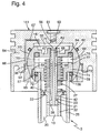
- FIG. 4 shows, broken away, a piston-side section of a connecting rod according to the invention with a two-stage fluid spring, which is formed by a connecting rod part 3 assigned to the crank pin and a connecting rod part 4 assigned to the piston of the reciprocating piston machine, with a cavity 25 of the connecting rod part 3 leading to the piston joint element 69 , as described in Fig. 3, wherein the piston joint element 69 is designed as a ball joint.
- a piston 55 is designed as a hollow body which is open towards the connecting rod and which comprises a spherically shaped bearing shell 53 for pivotally accommodating an articulated head 69 which is designed as a spherical layer.
- the bearing shell 53 is divided equatorially, the connecting rod half of the bearing shell being arranged on the inside of a clamping ring 65 which, when screwed into the piston 54, fixes the joint head 69, which is made in one or more parts, so as to be pivotable.
- the joint head 69 comprises a cylindrical space, which forms the pump chamber 15 and is directed towards the connecting rod part 3 on the crank pin side, into which the hollow body 25 of the connecting rod part 3 on the crank pin side is guided.
- An insert 73 is in the end section of the hollow body 25 screwed, which forms an outwardly directed annular shoulder 74, which projects beyond the outer dimension of the cross section of the hollow body 25 and with the sliding fit 36 formed on the circumferential surface of the annular shoulder 74 guides the joint head 69 - as in FIG. 3 - in a longitudinally movable manner.
- the pump chamber 15 is delimited by a radial wall 42 'which is integrally formed on the joint head 69 and which is screw-connected centrally by means of a slide thread 68 to a slide 42 passing through the pump chamber 15.
- the design of the slide 42 can essentially be found in the descriptions for the drawing figures 2 and 3.
- the wall 42 ' has a recess 76 which is open to the insert 73 and in which an elastomer ring 64 is arranged.
- the insert 73 has in the radially outer region an annular projection 77 which follows the contour of the radial wall 42 'and which is inserted into the recess in the wall 42' when the connecting rod parts 3 and 4 are pushed into one another. If the spring travel of the fluid spring is set slightly too far, the movement of the pressure piston 141 is buffered by the elastomer ring 64.
- an expanded pump chamber 15' is delimited, which communicates fluidically via the opening 62 passing through the slide 42 and via radial openings 39 in the slide 42 with the pump chamber 15 and with the cavity 10 of the connecting rod part 3 on the crank pin side .
- the piston crown 55 has a ventilation opening 67 which is connected via a ventilation channel 66 to the equatorial separation point of the bearing shell 53. In this case, the venting channel 66 feeds the bearing of the joint head 69 pressure lubricating oil from the enlarged pump chamber 15 '.
- the return of the pressure lubricating oil from the fluid spaces of the Connecting rod in the circuit of the pressure lubricating oil system of the reciprocating piston machine is provided as described for FIG. 3.
- Pressure oil is conducted from an intermediate space 57 through an L-shaped oil bore 59 in the joint head 69, which can be released from the annular shoulder 74 of the insert 73, into an area delimited between the clamping ring 65 and the hollow body 25 into the crankcase space.
- the pressure oil throughput of the connecting rod can be adjusted through the throttle cross section of the opening 67, whereby cooling of the piston crown 55 is also achieved.
- the lubricating oil of the part of the bearing 53 assigned to the clamping ring 65 emerges into the crankcase adjacent to the oil bore 59 in the joint head 69.
- a recess for receiving a sealing ring 60 is arranged in the piston 54 through the bearing shell 53.
- the weight of the reciprocating piston machine is reduced, since the spherical-layered joint head 69 is lighter than a piston pin 35 in a piston joint, as described for FIG. 3.
- the pivot axis of the spherical joint head 69 which is defined by the largest diameter of the bearing 53, is closer to the piston crown 55, as a result of which a further extension of the connecting rod part 3 on the crank pin side is achieved.
- the light piston follows the gas force in the cylinder of the reciprocating machine more quickly.
- the extension of the connecting rod part 3 on the crank pin side achieves a smaller pivoting angle of the piston joint and thus a smaller inclination of the connecting rod.
- crank pin-side connecting rod part 3 shown in FIGS. 3 and 4 into the piston joint element associated with the piston-side connecting rod part 4 in a connecting rod with a two-stage fluid spring can also be realized in a connecting rod according to the invention with a single-stage fluid spring.
- FIG. 5 shows, in a partially broken open partial view of the connecting rod part 3 of a connecting rod on the crank pin side with a single-flow fluid spring, an advantageous arrangement of a check valve 12, which prevents the backflow of pressure oil from the cavity 10.
- the pressure oil supply into the cavity 10 from the oil pressure system of the reciprocating machine, not shown, takes place largely as described in relation to FIG. 1 via a radial pressure oil line 11 in the crank pin 7 and an oil hole 14 penetrating a crank pin bearing 6, a crank pin eye 30 and a base plate 20 delimiting the cavity 10 , wherein the oil line 11 and the oil bore 14 are fluidly connected by a central crank pin bearing pocket 13 in the crank pin bearing 6.
- the check valve 12 is inserted between the end portion of the oil bore 14 and the cavity 10 in the base plate 26.
- check valve 12 in the base plate 26 downstream of the oil hole 14 prevents leakage of oil, in particular in the region of the crank pin bearing pocket 13 in the crank pin bearing 6 in the phase of high pressures in the fluid spaces of the connecting rod.
- FIG. 6 shows an arrangement of the check valve 12 in a connecting rod with a two-stage fluid spring, largely corresponding to the drawing FIG. 5, the oil bore 14 being made centrally in the base plate 26.
- the check valve 12 is arranged in the region of the base plate 26 in the pressure line 14, as a result of which backflow of the pressure oil conveyed into the cavity 10 delimited by an inner tube 32 is avoided. Leakage oil loss in the area of the supply line from the pressure oil lubrication system of the reciprocating piston machine into the cavity 10 of the energy accumulator of the connecting rod is thus counteracted.
Landscapes
- Engineering & Computer Science (AREA)
- General Engineering & Computer Science (AREA)
- Mechanical Engineering (AREA)
- Chemical & Material Sciences (AREA)
- Combustion & Propulsion (AREA)
- Shafts, Cranks, Connecting Bars, And Related Bearings (AREA)
- Compressor (AREA)
- Transmission Devices (AREA)
- Reciprocating Pumps (AREA)
Applications Claiming Priority (2)
| Application Number | Priority Date | Filing Date | Title |
|---|---|---|---|
| DE19530191 | 1995-08-17 | ||
| DE19530191A DE19530191A1 (de) | 1995-08-17 | 1995-08-17 | Pleuelstange |
Publications (2)
| Publication Number | Publication Date |
|---|---|
| EP0761995A1 true EP0761995A1 (fr) | 1997-03-12 |
| EP0761995B1 EP0761995B1 (fr) | 1999-11-24 |
Family
ID=7769666
Family Applications (1)
| Application Number | Title | Priority Date | Filing Date |
|---|---|---|---|
| EP96111923A Expired - Lifetime EP0761995B1 (fr) | 1995-08-17 | 1996-07-24 | Bielle |
Country Status (4)
| Country | Link |
|---|---|
| US (1) | US5724863A (fr) |
| EP (1) | EP0761995B1 (fr) |
| DE (2) | DE19530191A1 (fr) |
| ES (1) | ES2141418T3 (fr) |
Cited By (1)
| Publication number | Priority date | Publication date | Assignee | Title |
|---|---|---|---|---|
| RU2226626C2 (ru) * | 2002-07-12 | 2004-04-10 | Московский государственный открытый университет | Шатун двигателя |
Families Citing this family (60)
| Publication number | Priority date | Publication date | Assignee | Title |
|---|---|---|---|---|
| DE19724225A1 (de) * | 1997-06-03 | 1998-12-10 | Norbert Tornack | Steuerbarer Kurbelradius eines Hubkolbenverbrennungsmotors |
| GB9920210D0 (en) * | 1999-08-27 | 1999-10-27 | Lucas Industries Ltd | Fuel pump |
| US6467373B1 (en) * | 2000-10-02 | 2002-10-22 | General Motors Corporation | Flexible connecting rod |
| US6499446B1 (en) | 2000-10-18 | 2002-12-31 | Ford Global Technologies, Inc. | Variable compression ratio connecting rod locking mechanism I |
| US6408804B1 (en) | 2000-10-18 | 2002-06-25 | Ford Global Technologies, Inc. | Apparatus for varying the compression ratio of an internal combustion engine |
| US6497203B1 (en) | 2000-10-18 | 2002-12-24 | Ford Global Technologies, Inc. | Hydraulic circuit for unlocking variable compression ratio connecting rod locking mechanisms |
| US6622669B1 (en) | 2000-10-18 | 2003-09-23 | Ford Global Technologies, Llc | Hydraulic circuit having accumulator for unlocking variable compression ratio connecting rod locking mechanisms-II |
| US6386153B1 (en) | 2000-10-18 | 2002-05-14 | Ford Global Technologies, Inc. | Variable compression ratio connecting rod locking mechanism II |
| US6412453B1 (en) | 2000-10-18 | 2002-07-02 | Ford Global Technologies, Inc. | System and method for varying the compression ratio of an internal combustion engine |
| US6394048B1 (en) | 2001-01-16 | 2002-05-28 | Ford Global Technologies, Inc. | Variable compression ratio internal combustion engine using field-sensitive fluid |
| US20050145060A1 (en) * | 2001-02-22 | 2005-07-07 | Weaver Robert R. | Engine connecting rod for high performance applications and method of manufacture |
| US20080282838A1 (en) * | 2001-02-22 | 2008-11-20 | Weaver Robert R | Engine connecting rod for high performance applications and method of manufacture |
| DE50104202D1 (de) * | 2001-03-19 | 2004-11-25 | Ford Global Tech Inc | Laengenverstellbare Pleuelstange |
| US6394047B1 (en) | 2001-08-10 | 2002-05-28 | Ford Global Technologies, Inc. | Connecting rod for a variable compression engine |
| US6644171B2 (en) | 2001-10-05 | 2003-11-11 | Ford Global Technologies, Llc | Variable compression connecting rod |
| US6745619B2 (en) * | 2001-10-22 | 2004-06-08 | Ford Global Technologies, Llc | Diagnostic method for variable compression ratio engine |
| US6612288B2 (en) | 2001-11-06 | 2003-09-02 | Ford Global Technologies, Llc | Diagnostic method for variable compression ratio engine |
| US6668768B2 (en) * | 2001-11-15 | 2003-12-30 | Ford Global Technologies, Llc | Variable compression ratio engine |
| US6876916B2 (en) * | 2002-02-01 | 2005-04-05 | Ford Global Technologies, Llc | Method and system for inferring torque output of a variable compression ratio engine |
| US6732041B2 (en) * | 2002-04-25 | 2004-05-04 | Ford Global Technologies, Llc | Method and system for inferring intake manifold pressure of a variable compression ratio engine |
| US6705255B2 (en) | 2002-06-25 | 2004-03-16 | Ford Global Technologies, Llc | Crankshaft for use with a variable compression ratio system |
| US20040187632A1 (en) * | 2003-03-26 | 2004-09-30 | Siegfried Meyer | Spring-supported coupling structure for use in an engine |
| US20040187633A1 (en) * | 2003-03-26 | 2004-09-30 | Siegfried Meyer | Extendable coupling structure for use in an engine |
| US20040187634A1 (en) * | 2003-03-26 | 2004-09-30 | Siegfried Meyer | Spring-based crankshaft coupling structure for engine |
| US7610894B2 (en) * | 2005-05-16 | 2009-11-03 | Fsnc, Llc | Self-compensating cylinder system in a process cycle |
| JP4640236B2 (ja) * | 2006-04-05 | 2011-03-02 | 日産自動車株式会社 | 内燃機関の始動装置 |
| US20080017164A1 (en) * | 2006-07-21 | 2008-01-24 | Advanced Propulsion Technologies, Inc. | Piston-pin bearing lubrication system and method for a two sroke internal combustion engine |
| DE102006042072A1 (de) * | 2006-09-05 | 2008-03-06 | Horst Prof. Dr. Gentsch | Pleuelstange |
| DE102007026312A1 (de) | 2007-06-06 | 2008-12-11 | Karl Richter | Pleuelstange für Hubkolbenmotore |
| DE102007042156A1 (de) * | 2007-09-05 | 2009-03-12 | Man Diesel Se | Verbindungsanordnung, insbesondere zum Verspannen eines Zylinderkopfes, mit einem Kurbelgehäuse einer Hubkolbenbrennkraftmaschine |
| US7827943B2 (en) * | 2008-02-19 | 2010-11-09 | Tonand Brakes Inc | Variable compression ratio system |
| DE102008001206A1 (de) | 2008-04-16 | 2009-11-05 | Horst Prof. Dr. Gentsch | Pleuelstange |
| US8468997B2 (en) * | 2009-08-06 | 2013-06-25 | Larry C. Wilkins | Internal combustion engine with variable effective length connecting rod |
| AT513054B1 (de) * | 2012-07-03 | 2014-09-15 | Avl List Gmbh | Längenverstellbare Pleuelstange |
| US9068530B2 (en) * | 2013-03-15 | 2015-06-30 | Mahle International Gmbh | Connecting rod with lubrication passage |
| AT514071B1 (de) * | 2013-10-18 | 2014-10-15 | Avl List Gmbh | Längenverstellbare Pleuelstange |
| US9624826B2 (en) * | 2014-03-24 | 2017-04-18 | Freddie Ray Roberts | Variable compression cylinder head, crankshaft, and piston rod and system thereof |
| DE102015001066B3 (de) * | 2015-01-29 | 2015-10-22 | Armin Brunner | Hydraulisch längenverstellbare Pleuelstange |
| AT516387B1 (de) * | 2015-03-31 | 2016-05-15 | Avl List Gmbh | Längenverstellbare pleuelstange |
| AT517511A1 (de) | 2015-08-10 | 2017-02-15 | Avl List Gmbh | Hubkolbenmaschine, insbesondere brennkraftmaschine |
| FR3043739B1 (fr) * | 2015-11-17 | 2018-06-15 | MCE 5 Development | Bielle pour moteur a rapport volumetrique variable |
| FR3043740B1 (fr) * | 2015-11-17 | 2018-01-05 | MCE 5 Development | Bielle pour moteur a rapport volumetrique variable |
| FR3043720B1 (fr) | 2015-11-17 | 2019-11-08 | MCE 5 Development | Moteur a rapport volumetrique variable |
| CN108603438B (zh) | 2015-12-14 | 2022-01-25 | Avl 里斯脱有限公司 | 长度可调节的连杆、往复式活塞发动机和车辆 |
| AT519011B1 (de) | 2016-05-31 | 2018-03-15 | Avl List Gmbh | Hubkolbenmaschine |
| DE102016008306A1 (de) | 2016-07-06 | 2018-01-11 | Avl List Gmbh | Pleuel mit verstellbarer Pleuellänge |
| US20170009647A1 (en) * | 2016-09-22 | 2017-01-12 | Caterpillar Inc. | Connecting rod |
| DE102016120950A1 (de) * | 2016-11-03 | 2018-05-03 | Avl List Gmbh | Pleuelstange mit gekapselter Baugruppe zur Längenverstellung |
| DE102016120975A1 (de) * | 2016-11-03 | 2018-05-03 | Avl List Gmbh | Längenverstellbare Pleuelstange mit einer Zylinder-Kolben-Einheit mit Ölfilter |
| AT519360B1 (de) | 2017-02-24 | 2018-06-15 | Avl List Gmbh | Verfahren zum Betrieb einer Hubkolbenmaschine mit wenigstens einer hydraulisch längenverstellbaren Pleuelstange |
| DE102017110446A1 (de) | 2017-05-15 | 2018-11-15 | ECO Holding 1 GmbH | Pleuel für eine Brennkraftmaschine mit variabler Verdichtung |
| DE102017221468A1 (de) * | 2017-11-29 | 2019-05-29 | Audi Ag | Brennkraftmaschine sowie Verfahren zum Betreiben einer Brennkraftmaschine |
| DE102018115727B3 (de) * | 2018-06-29 | 2019-11-07 | Dr. Ing. H.C. F. Porsche Aktiengesellschaft | Abstützanordnung für ein Exzenterorgan einer Verstellanordnung sowie Verstellanordnung |
| DE102018124781A1 (de) * | 2018-10-08 | 2020-04-09 | Avl List Gmbh | Montageverfahren zum Fügen des teleskopierbaren Stangenteils eines VCR-Pleuels |
| US11371609B2 (en) * | 2018-10-26 | 2022-06-28 | Ted Hollinger | Systems, devices, and/or methods for improving engine efficiency |
| CN111828170B (zh) * | 2019-04-16 | 2021-11-23 | 广州汽车集团股份有限公司 | 用于可变压缩比发动机的连杆 |
| US11149782B2 (en) | 2019-07-17 | 2021-10-19 | Hyundai Motor Company | Magnetically-actuated variable-length connecting rod devices and methods for controlling the same |
| US10760481B1 (en) | 2019-07-17 | 2020-09-01 | Hyundai Motor Company | Magnetically-actuated variable-length connecting rod devices and methods for controlling the same |
| US11215113B2 (en) | 2019-07-17 | 2022-01-04 | Hyundai Motor Company | Magnetically-actuated variable-length connecting rod devices and methods for controlling the same |
| GB2634109A (en) * | 2023-09-30 | 2025-04-02 | Sayed Ahmed Habib Mustafa | Efficiency-boosting arrangement for reciprocating internal combustion engines |
Citations (8)
| Publication number | Priority date | Publication date | Assignee | Title |
|---|---|---|---|---|
| US1610137A (en) * | 1926-01-28 | 1926-12-07 | Charles E Kratsch | Connecting rod |
| CH252208A (de) * | 1945-08-21 | 1947-12-15 | Gfeller Ernst | Kurbelgetriebe, insbesondere für Verbrennungs-Kraftmaschinen. |
| US2523631A (en) * | 1948-02-03 | 1950-09-26 | Gen Nailing Mach | Connecting rod unit |
| US2580825A (en) * | 1946-04-29 | 1952-01-01 | Electro Hydraulics Ltd | Shock absorbing means |
| DE2734447A1 (de) * | 1977-07-30 | 1979-02-08 | Bruno Ing Grad Sommer | Explosionshubkolbenmotor |
| SU912962A1 (ru) * | 1980-04-03 | 1982-03-15 | Машиностроительный завод им.Ф.Э.Дзержинского | Шатун переменной длины |
| US4703838A (en) * | 1980-05-27 | 1987-11-03 | Caterpillar Tractor Co. | Recoil damper for a reciprocating member |
| DE3735415A1 (de) * | 1987-10-20 | 1989-05-03 | Karlheinz Menkhoff | Elastomer-federstossdaempfer |
Family Cites Families (11)
| Publication number | Priority date | Publication date | Assignee | Title |
|---|---|---|---|---|
| US2104802A (en) * | 1935-03-15 | 1938-01-11 | Einar H Hansen | Pneumatic differential piston for internal combustion engines |
| US2134995A (en) * | 1935-11-13 | 1938-11-01 | George A Anderson | Adjustable stroke and shock absorbing connecting rod |
| US2252153A (en) * | 1940-06-17 | 1941-08-12 | Mary Adeline Reynolds | Internal combustion engine |
| US4140091A (en) * | 1977-03-09 | 1979-02-20 | Showers Jr Lewis M | Uniform compression piston engine |
| US4111164A (en) * | 1977-09-27 | 1978-09-05 | Wuerfel Robert P | Variable displacement arrangement in four cycle, reciprocating internal combustion engine |
| FR2411341A1 (fr) * | 1977-12-12 | 1979-07-06 | Messier Hispano Sa | Suspension oleopneumatique a orifices de laminage variables, notamment pour trains d'atterrissage d'aerodynes |
| US4370901A (en) * | 1981-01-05 | 1983-02-01 | John Sawyer | Connecting rod with variable length |
| DE3224769A1 (de) * | 1981-11-19 | 1983-05-26 | Robert Bosch Gmbh, 7000 Stuttgart | Kraftstoffeinspritzeinrichtung fuer brennkraftmaschinen, insbesondere pumpeduese fuer dieselbrennkraftmaschinen |
| DE3339360A1 (de) * | 1983-10-29 | 1985-05-09 | Gerard 4993 Rahden Brozio | Pleuelstange eines hubkolbenmotors |
| DE3804859A1 (de) * | 1988-02-17 | 1989-08-31 | Schwarz Helmut | Federkraft-pleuel |
| US4966109A (en) * | 1989-04-05 | 1990-10-30 | Hitachi Construction Machinery Co., Ltd. | Hydraulic connecting rod |
-
1995
- 1995-08-17 DE DE19530191A patent/DE19530191A1/de not_active Withdrawn
-
1996
- 1996-07-24 DE DE59603707T patent/DE59603707D1/de not_active Expired - Fee Related
- 1996-07-24 EP EP96111923A patent/EP0761995B1/fr not_active Expired - Lifetime
- 1996-07-24 ES ES96111923T patent/ES2141418T3/es not_active Expired - Lifetime
- 1996-08-15 US US08/698,093 patent/US5724863A/en not_active Expired - Fee Related
Patent Citations (8)
| Publication number | Priority date | Publication date | Assignee | Title |
|---|---|---|---|---|
| US1610137A (en) * | 1926-01-28 | 1926-12-07 | Charles E Kratsch | Connecting rod |
| CH252208A (de) * | 1945-08-21 | 1947-12-15 | Gfeller Ernst | Kurbelgetriebe, insbesondere für Verbrennungs-Kraftmaschinen. |
| US2580825A (en) * | 1946-04-29 | 1952-01-01 | Electro Hydraulics Ltd | Shock absorbing means |
| US2523631A (en) * | 1948-02-03 | 1950-09-26 | Gen Nailing Mach | Connecting rod unit |
| DE2734447A1 (de) * | 1977-07-30 | 1979-02-08 | Bruno Ing Grad Sommer | Explosionshubkolbenmotor |
| SU912962A1 (ru) * | 1980-04-03 | 1982-03-15 | Машиностроительный завод им.Ф.Э.Дзержинского | Шатун переменной длины |
| US4703838A (en) * | 1980-05-27 | 1987-11-03 | Caterpillar Tractor Co. | Recoil damper for a reciprocating member |
| DE3735415A1 (de) * | 1987-10-20 | 1989-05-03 | Karlheinz Menkhoff | Elastomer-federstossdaempfer |
Cited By (1)
| Publication number | Priority date | Publication date | Assignee | Title |
|---|---|---|---|---|
| RU2226626C2 (ru) * | 2002-07-12 | 2004-04-10 | Московский государственный открытый университет | Шатун двигателя |
Also Published As
| Publication number | Publication date |
|---|---|
| DE59603707D1 (de) | 1999-12-30 |
| EP0761995B1 (fr) | 1999-11-24 |
| DE19530191A1 (de) | 1997-02-20 |
| ES2141418T3 (es) | 2000-03-16 |
| US5724863A (en) | 1998-03-10 |
Similar Documents
| Publication | Publication Date | Title |
|---|---|---|
| EP0761995B1 (fr) | Bielle | |
| DE69105573T2 (de) | Verbindungsstruktur einer Kolben- und Pleuelstange. | |
| EP3746676B1 (fr) | Amortisseur de vibrations pour un véhicule | |
| DE102020002316B3 (de) | Brennkraftmaschine mit verstellbarem Pleuel | |
| AT15006U2 (de) | Längenverstellbare Pleuelstange | |
| DE2632440C2 (de) | Brennkraftmaschine mit veränderlichem Kompressionsverhältnis | |
| AT519305B1 (de) | Längenverstellbare Pleuelstange mit einer Zylinder-Kolben-Einheit mit mehreren Kolbendichtungen | |
| DE102004011284A1 (de) | Hochdruckpumpe, insbesondere für eine Kraftstoffeinspritzeinrichtung einer Brennkraftmaschine | |
| DE102007026312A1 (de) | Pleuelstange für Hubkolbenmotore | |
| DE102015202538A1 (de) | Hydraulisch betätigtes Schaltventil für eine Vorrichtung zur Veränderung des Verdichtungsverhältnisses einer Zylindereinheit | |
| DE102016120950A1 (de) | Pleuelstange mit gekapselter Baugruppe zur Längenverstellung | |
| DE102016203559A1 (de) | Hydraulisch betätigtes Schaltventil | |
| EP0881380A1 (fr) | Pompe d'alimentation haute-pression | |
| AT519294A2 (de) | Längenverstellbare Pleuelstange mit einer Zylinder-Kolben-Einheit mit Zylinderhülse | |
| AT519293B1 (de) | Längenverstellbare Pleuelstange mit einer Zylinder-Kolben-Einheit mit Ölführungsstange | |
| DE10304685A1 (de) | Verbrennungsmotor mit veränderbarem Verdichtungsverhältnis | |
| AT519307B1 (de) | Längenverstellbare Pleuelstange mit einer Zylinder-Kolben-Einheit mit konischer Spaltdichtung | |
| DE19859442C1 (de) | Hydrostatische Kolbenmaschine | |
| AT524567B1 (de) | Längenverstellbare Pleuelstange mit kompaktem Ablassventil | |
| DE102015213286A1 (de) | Stützzylinder einer Vorrichtung zur Veränderung des Verdichtungsverhältnisses einer Zylindereinheit einer Hubkolbenbrennkraftmaschine | |
| DE1809160B2 (de) | Ventilanordnung in einem arbeitskolben einer hubkolben-brennkraftmaschine mit selbsttaetig veraenderbarem kompressionsverhaeltnis | |
| AT522194B1 (de) | Steuerschieber mit separatem Steuerkolben für eine längenverstellbare Pleuelstange | |
| AT522160B1 (de) | Steuerschieber für eine längsverstellbare Pleuelstange | |
| AT522793B1 (de) | Kompakter hydraulischer Ventilmechanismus für eine längenverstellbare Pleuelstange | |
| AT521146B1 (de) | Hydraulisches Steuerventil für eine längenverstellbare Pleuelstange mit einem Hohlschieber |
Legal Events
| Date | Code | Title | Description |
|---|---|---|---|
| PUAI | Public reference made under article 153(3) epc to a published international application that has entered the european phase |
Free format text: ORIGINAL CODE: 0009012 |
|
| AK | Designated contracting states |
Kind code of ref document: A1 Designated state(s): DE ES FR GB IT |
|
| 17P | Request for examination filed |
Effective date: 19970212 |
|
| 17Q | First examination report despatched |
Effective date: 19971202 |
|
| GRAG | Despatch of communication of intention to grant |
Free format text: ORIGINAL CODE: EPIDOS AGRA |
|
| RAP1 | Party data changed (applicant data changed or rights of an application transferred) |
Owner name: DAIMLERCHRYSLER AG |
|
| GRAG | Despatch of communication of intention to grant |
Free format text: ORIGINAL CODE: EPIDOS AGRA |
|
| GRAH | Despatch of communication of intention to grant a patent |
Free format text: ORIGINAL CODE: EPIDOS IGRA |
|
| GRAH | Despatch of communication of intention to grant a patent |
Free format text: ORIGINAL CODE: EPIDOS IGRA |
|
| GRAA | (expected) grant |
Free format text: ORIGINAL CODE: 0009210 |
|
| ITF | It: translation for a ep patent filed | ||
| AK | Designated contracting states |
Kind code of ref document: B1 Designated state(s): DE ES FR GB IT |
|
| REF | Corresponds to: |
Ref document number: 59603707 Country of ref document: DE Date of ref document: 19991230 |
|
| GBT | Gb: translation of ep patent filed (gb section 77(6)(a)/1977) |
Effective date: 19991210 |
|
| ET | Fr: translation filed | ||
| REG | Reference to a national code |
Ref country code: ES Ref legal event code: FG2A Ref document number: 2141418 Country of ref document: ES Kind code of ref document: T3 |
|
| PLBE | No opposition filed within time limit |
Free format text: ORIGINAL CODE: 0009261 |
|
| STAA | Information on the status of an ep patent application or granted ep patent |
Free format text: STATUS: NO OPPOSITION FILED WITHIN TIME LIMIT |
|
| 26N | No opposition filed | ||
| PGFP | Annual fee paid to national office [announced via postgrant information from national office to epo] |
Ref country code: GB Payment date: 20010614 Year of fee payment: 6 |
|
| PGFP | Annual fee paid to national office [announced via postgrant information from national office to epo] |
Ref country code: ES Payment date: 20010716 Year of fee payment: 6 |
|
| REG | Reference to a national code |
Ref country code: GB Ref legal event code: IF02 |
|
| PGFP | Annual fee paid to national office [announced via postgrant information from national office to epo] |
Ref country code: FR Payment date: 20020711 Year of fee payment: 7 Ref country code: DE Payment date: 20020711 Year of fee payment: 7 |
|
| PG25 | Lapsed in a contracting state [announced via postgrant information from national office to epo] |
Ref country code: GB Free format text: LAPSE BECAUSE OF NON-PAYMENT OF DUE FEES Effective date: 20020724 |
|
| PG25 | Lapsed in a contracting state [announced via postgrant information from national office to epo] |
Ref country code: ES Free format text: LAPSE BECAUSE OF NON-PAYMENT OF DUE FEES Effective date: 20020725 |
|
| GBPC | Gb: european patent ceased through non-payment of renewal fee |
Effective date: 20020724 |
|
| PG25 | Lapsed in a contracting state [announced via postgrant information from national office to epo] |
Ref country code: DE Free format text: LAPSE BECAUSE OF NON-PAYMENT OF DUE FEES Effective date: 20040203 |
|
| PG25 | Lapsed in a contracting state [announced via postgrant information from national office to epo] |
Ref country code: FR Free format text: LAPSE BECAUSE OF NON-PAYMENT OF DUE FEES Effective date: 20040331 |
|
| REG | Reference to a national code |
Ref country code: FR Ref legal event code: ST |
|
| REG | Reference to a national code |
Ref country code: ES Ref legal event code: FD2A Effective date: 20030811 |
|
| PG25 | Lapsed in a contracting state [announced via postgrant information from national office to epo] |
Ref country code: IT Free format text: LAPSE BECAUSE OF NON-PAYMENT OF DUE FEES;WARNING: LAPSES OF ITALIAN PATENTS WITH EFFECTIVE DATE BEFORE 2007 MAY HAVE OCCURRED AT ANY TIME BEFORE 2007. THE CORRECT EFFECTIVE DATE MAY BE DIFFERENT FROM THE ONE RECORDED. Effective date: 20050724 |