EP0762005A1 - Moteur de frein à transmission hydraulique - Google Patents
Moteur de frein à transmission hydraulique Download PDFInfo
- Publication number
- EP0762005A1 EP0762005A1 EP96112837A EP96112837A EP0762005A1 EP 0762005 A1 EP0762005 A1 EP 0762005A1 EP 96112837 A EP96112837 A EP 96112837A EP 96112837 A EP96112837 A EP 96112837A EP 0762005 A1 EP0762005 A1 EP 0762005A1
- Authority
- EP
- European Patent Office
- Prior art keywords
- hydraulic
- piston
- chamber
- brake
- hydraulic cylinder
- Prior art date
- Legal status (The legal status is an assumption and is not a legal conclusion. Google has not performed a legal analysis and makes no representation as to the accuracy of the status listed.)
- Granted
Links
- 230000005540 biological transmission Effects 0.000 title claims description 11
- 239000012530 fluid Substances 0.000 abstract description 14
- 150000001875 compounds Chemical class 0.000 abstract 1
- 230000008859 change Effects 0.000 description 4
- 230000007246 mechanism Effects 0.000 description 3
- 238000006243 chemical reaction Methods 0.000 description 2
- 230000008901 benefit Effects 0.000 description 1
- 210000003746 feather Anatomy 0.000 description 1
- 238000012423 maintenance Methods 0.000 description 1
- 238000000034 method Methods 0.000 description 1
- 230000008569 process Effects 0.000 description 1
Images

Classifications
-
- F—MECHANICAL ENGINEERING; LIGHTING; HEATING; WEAPONS; BLASTING
- F16—ENGINEERING ELEMENTS AND UNITS; GENERAL MEASURES FOR PRODUCING AND MAINTAINING EFFECTIVE FUNCTIONING OF MACHINES OR INSTALLATIONS; THERMAL INSULATION IN GENERAL
- F16D—COUPLINGS FOR TRANSMITTING ROTATION; CLUTCHES; BRAKES
- F16D65/00—Parts or details
- F16D65/14—Actuating mechanisms for brakes; Means for initiating operation at a predetermined position
- F16D65/16—Actuating mechanisms for brakes; Means for initiating operation at a predetermined position arranged in or on the brake
- F16D65/18—Actuating mechanisms for brakes; Means for initiating operation at a predetermined position arranged in or on the brake adapted for drawing members together, e.g. for disc brakes
-
- B—PERFORMING OPERATIONS; TRANSPORTING
- B60—VEHICLES IN GENERAL
- B60T—VEHICLE BRAKE CONTROL SYSTEMS OR PARTS THEREOF; BRAKE CONTROL SYSTEMS OR PARTS THEREOF, IN GENERAL; ARRANGEMENT OF BRAKING ELEMENTS ON VEHICLES IN GENERAL; PORTABLE DEVICES FOR PREVENTING UNWANTED MOVEMENT OF VEHICLES; VEHICLE MODIFICATIONS TO FACILITATE COOLING OF BRAKES
- B60T13/00—Transmitting braking action from initiating means to ultimate brake actuator with power assistance or drive; Brake systems incorporating such transmitting means, e.g. air-pressure brake systems
- B60T13/74—Transmitting braking action from initiating means to ultimate brake actuator with power assistance or drive; Brake systems incorporating such transmitting means, e.g. air-pressure brake systems with electrical assistance or drive
- B60T13/745—Transmitting braking action from initiating means to ultimate brake actuator with power assistance or drive; Brake systems incorporating such transmitting means, e.g. air-pressure brake systems with electrical assistance or drive acting on a hydraulic system, e.g. a master cylinder
-
- F—MECHANICAL ENGINEERING; LIGHTING; HEATING; WEAPONS; BLASTING
- F16—ENGINEERING ELEMENTS AND UNITS; GENERAL MEASURES FOR PRODUCING AND MAINTAINING EFFECTIVE FUNCTIONING OF MACHINES OR INSTALLATIONS; THERMAL INSULATION IN GENERAL
- F16D—COUPLINGS FOR TRANSMITTING ROTATION; CLUTCHES; BRAKES
- F16D65/00—Parts or details
- F16D65/38—Slack adjusters
- F16D65/72—Slack adjusters hydraulic
- F16D65/74—Slack adjusters hydraulic self-acting in one direction
-
- F—MECHANICAL ENGINEERING; LIGHTING; HEATING; WEAPONS; BLASTING
- F16—ENGINEERING ELEMENTS AND UNITS; GENERAL MEASURES FOR PRODUCING AND MAINTAINING EFFECTIVE FUNCTIONING OF MACHINES OR INSTALLATIONS; THERMAL INSULATION IN GENERAL
- F16D—COUPLINGS FOR TRANSMITTING ROTATION; CLUTCHES; BRAKES
- F16D2121/00—Type of actuator operation force
- F16D2121/18—Electric or magnetic
- F16D2121/24—Electric or magnetic using motors
-
- F—MECHANICAL ENGINEERING; LIGHTING; HEATING; WEAPONS; BLASTING
- F16—ENGINEERING ELEMENTS AND UNITS; GENERAL MEASURES FOR PRODUCING AND MAINTAINING EFFECTIVE FUNCTIONING OF MACHINES OR INSTALLATIONS; THERMAL INSULATION IN GENERAL
- F16D—COUPLINGS FOR TRANSMITTING ROTATION; CLUTCHES; BRAKES
- F16D2125/00—Components of actuators
- F16D2125/02—Fluid-pressure mechanisms
- F16D2125/10—Plural pistons interacting by fluid pressure, e.g. hydraulic force amplifiers using different sized pistons
-
- F—MECHANICAL ENGINEERING; LIGHTING; HEATING; WEAPONS; BLASTING
- F16—ENGINEERING ELEMENTS AND UNITS; GENERAL MEASURES FOR PRODUCING AND MAINTAINING EFFECTIVE FUNCTIONING OF MACHINES OR INSTALLATIONS; THERMAL INSULATION IN GENERAL
- F16D—COUPLINGS FOR TRANSMITTING ROTATION; CLUTCHES; BRAKES
- F16D2125/00—Components of actuators
- F16D2125/18—Mechanical mechanisms
- F16D2125/20—Mechanical mechanisms converting rotation to linear movement or vice versa
- F16D2125/34—Mechanical mechanisms converting rotation to linear movement or vice versa acting in the direction of the axis of rotation
- F16D2125/40—Screw-and-nut
Definitions
- the invention relates to a brake actuator with a hydraulic transmission, consisting of an electric motor as a drive element, a conversion device for converting the rotational movement of the electric motor into a linear movement, and a hydraulic transmission for transmitting the linear movement of the conversion device to a friction lining of a brake.
- DE 42 29 042 describes such a brake actuator, which is provided with an electric motor and a threaded spindle.
- the threaded spindle is driven by a motor and the spindle nut is connected to a first hydraulic piston connected to a hydraulic chamber.
- a second hydraulic piston can act on a friction lining in order to carry out a braking operation.
- Older rights consist of a brake actuator shown in patent application DE 195 19 308.3, which is characterized in comparison with the brake actuator described in DE 42 29 042 in particular by reversing the function of the spindle. Thereafter, the spindle (rod) is not, as usual, in direct operative connection with the drive motor, but rather the spindle nut is non-positively attached to the motor axis. The threaded spindle (the spindle rod), however, is in a non-positive connection with the primary piston of an adjoining hydraulic gear.
- Brake linings are subject to wear. During the operation of a friction brake, the friction surface is gradually removed. This increases the distance between the pad and the brake disc. In order to avoid that the distance between the lining and the brake disc becomes insurmountable, the brake must be readjusted, if not constantly, at least from time to time. Such an adjustment option is not provided in the brake actuation devices mentioned above.
- the object of the present invention is to describe a hydraulic adjustment for a friction brake, in which a defined distance of the linings from the brake disc is always guaranteed in the unbraked state.
- a further hydraulic chamber which can be referred to as an adjustment chamber, which is closed with a compensating piston which is movable with respect to the outside, and which is connected to the pressure chamber via an opening in the second hydraulic piston.
- the opening is provided with a (first) check valve pointing towards the pressure chamber.
- the first hydraulic cylinder is a housing-fixed structure provided with a hollow axis. It has a T-shaped longitudinal section. This first hydraulic cylinder also serves as a second hydraulic piston. This combination of two functions saves one component.
- the second hydraulic cylinder is cup-shaped and axially displaceable relative to the second hydraulic piston.
- first and second hydraulic pistons or first and second hydraulic cylinders are arranged coaxially one above the other, this results in an extremely short overall length. This is particularly advantageous since the space available in the area of the wheel brakes is limited.
- Another advantage of the coaxial arrangement of the two cylinders is that this structure results in a large gear ratio, to a certain extent informally.
- the first hydraulic piston (plunger) is retracted so far that it releases the mouth of a reset channel located between the pressure chamber and the adjustment chamber, which is secured against the adjustment chamber by a further check valve.
- the reset channel (the reset hole) can be dispensed with if the first check valve is designed in such a way that it opens easily in an unpressurized state and closes immediately at a certain excess pressure. This means that if the plunger is driven forward by the motor and builds up pressure, this check valve closes immediately. If you change the brake pads slowly, quasi-statically pushes the brake pad back by hand or mechanism, then the check valve remains open. This means that if a certain differential pressure or a certain flow velocity in this channel is exceeded, then this check valve closes suddenly. However, if this differential pressure is not exceeded, it remains open. This means that by slowly, quasi-statically pushing back the hydraulic cup or the pressure cup, it is possible to convey the fluid from the pressure chamber back into the compensation chamber.
- this valve for. B. remains partially open by a weak spring and closes immediately when pressure builds up.
- the first hydraulic piston (plunger) is reliably sealed from the cylindrical inner surface of the first hydraulic cylinder, the second hydraulic piston from the inner surface of the second hydraulic cylinder, and the compensating piston is reliably sealed both from the outer surface of the first hydraulic cylinder and from the inner surface of the second hydraulic cylinder by means of piston rings .
- the adjustment according to the invention takes place automatically with each braking operation.
- the components required for the adjustment are fully integrated in the hydraulic wheel brake actuator, resulting in a closed, locally limited hydraulic system. Due to the adjustment space acting as a "reservoir”, extended maintenance intervals can be applied with regard to the hydraulic fluid.
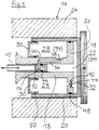
- a brake actuator with a hydraulic component essentially consists of an electric motor 2, preferably with a hollow shaft 4, and an adjoining threaded spindle 8, 10, which is composed of a spindle nut 8 and a spindle rod 10, and wherein the spindle nut 8 with the rotor 6 the motor 2 is in operative connection, for. B. by the spindle nut 8 is flanged directly coaxially fixed to the rotor 6 of the motor 2, as shown in the embodiment of FIG. 2.
- the spindle nut 8 rotatable with the rotor 6 of the motor 2 can be screwed onto the spindle rod 10 for the purpose of propelling it.
- the spindle rod 10 is displaceable in the longitudinal direction but is secured against rotation with respect to the housing 12 of the brake actuator and is either non-positively connected to a first hydraulic piston (plunger) 14 or there is even a functional unit of the spindle rod 10 and the first hydraulic piston 14.
- the first hydraulic piston 14 is part of a hydraulic transmission 16.
- the hydraulic transmission 16 further comprises: a (first) hydraulic cylinder 18, which in the present exemplary embodiment also represents a second hydraulic piston 18.
- the hydraulic chamber (pressure chamber) 22 enclosed by a second, longitudinally displaceable hydraulic cylinder 20 is delimited on the one hand by the first hydraulic piston (plunger) 14 and on the other hand by the second hydraulic piston 18 (which is also the first hydraulic cylinder 18).
- the end face of the second, longitudinally displaceable hydraulic cylinder 20 is closed.
- a brake caliper 24 is fastened on its cylinder surface, and a brake lining 26 is fastened on its front surface.
- the first hydraulic cylinder 18 is identical to the second hydraulic piston 18 in the brake actuator according to the invention, so that, in addition, only one (first) hydraulic piston (plunger) 14 and a (second) cup-shaped hydraulic cylinder 20 is required.
- the first hydraulic piston 14 moves within the combined first hydraulic cylinder / second hydraulic piston 18, the second, cylinder-shaped hydraulic cylinder 20 placed over the second hydraulic piston 18 moves coaxially to the first hydraulic piston 14. Because of the coaxial structure, it is inevitable that the diameter of the second hydraulic piston 18 (or the second hydraulic cylinder 20) is larger than the diameter of the first hydraulic piston (plunger) 14 (or the first hydraulic cylinder 18), which results in a power transmission.
- the adjustment mechanism according to the invention provided with the hydraulic component is formed within the cup-shaped second hydraulic cylinder 20 by a further hydraulic chamber, the so-called adjustment space 28.
- This adjustment chamber 28 is delimited on the one hand by the rear side of the second hydraulic piston 18 and on the other hand by a compensating piston 30 in relation to the outside space.
- the adjustment chamber 28 is connected to the pressure chamber 22 via an opening 44 located in the second hydraulic piston 18 and provided with a (first) check valve 32.
- This check valve 32 opens as soon as the first hydraulic piston 14 is retracted, provided that the second hydraulic cylinder 20 is not in the same dimensions is tracked.
- hydraulic fluid (fluid) 34 flows from the adjustment chamber 28 into the pressure chamber 22.
- the compensating piston 30 dips into the adjustment chamber 28 in accordance with the loss of volume.
- the mouth leading to the pressure chamber 22 is in the normal rest position and during operation of the brake 40 of the resetting channel 36 is closed by the first hydraulic piston (plunger) 14 which is advanced with the spindle rod 10.
- the hydraulic component with the adjustment mechanism according to the invention works as follows:
- the plunger 14 When a braking operation is initiated, the plunger 14 is advanced by the motor 2 by means of the threaded spindle 8, 10 and the corresponding brake pressure is built up in the pressure chamber 22.
- the check valve 32 located between the pressure chamber 22 and the adjustment chamber 28 prevents pressure equalization between these two areas.
- the (second) hydraulic cylinder 20 with the brake lining 26 is advanced by a certain distance.
- the hydraulic cylinder 20 moves back due to elasticity and disc blow.
- the fluid 34 In the event of a change in the brake lining 26, the fluid 34 must pass from the pressure chamber 22 into the adjustment chamber 28.
- the plunger 14 is retracted by means of the spindle rod 10 until it releases the reset channel 36.
- the fluid 34 passes from the pressure chamber 22 via the return channel 36 into the readjustment chamber 28.
- the first check valve 32 can be equipped with a weak spring 42 for the purpose of facilitating a change of lining.
- this spring 42 the check valve 32 remains open up to a certain excess pressure in quasi-static flow conditions. However, if a predetermined differential pressure or a certain flow rate is exceeded, the check valve 32 closes suddenly.
Landscapes
- Engineering & Computer Science (AREA)
- General Engineering & Computer Science (AREA)
- Mechanical Engineering (AREA)
- Transportation (AREA)
- Braking Arrangements (AREA)
Applications Claiming Priority (2)
| Application Number | Priority Date | Filing Date | Title |
|---|---|---|---|
| DE19529791A DE19529791C2 (de) | 1995-08-12 | 1995-08-12 | Bremsaktor mit Nachstellvorrichtung |
| DE19529791 | 1995-08-12 |
Publications (2)
| Publication Number | Publication Date |
|---|---|
| EP0762005A1 true EP0762005A1 (fr) | 1997-03-12 |
| EP0762005B1 EP0762005B1 (fr) | 1999-12-01 |
Family
ID=7769393
Family Applications (1)
| Application Number | Title | Priority Date | Filing Date |
|---|---|---|---|
| EP96112837A Expired - Lifetime EP0762005B1 (fr) | 1995-08-12 | 1996-08-09 | Moteur de frein à transmission hydraulique |
Country Status (3)
| Country | Link |
|---|---|
| US (1) | US5682965A (fr) |
| EP (1) | EP0762005B1 (fr) |
| DE (2) | DE19529791C2 (fr) |
Families Citing this family (21)
| Publication number | Priority date | Publication date | Assignee | Title |
|---|---|---|---|---|
| GB9521868D0 (en) * | 1995-10-25 | 1996-01-03 | Lucas Ind Plc | Improvements in electrically-operated disc brake assemblies for vehicles |
| DE19601983C1 (de) * | 1996-01-20 | 1997-07-24 | Continental Ag | Bremsanlage für ein Kraftfahrzeug |
| DE19741865C1 (de) * | 1997-09-23 | 1998-06-18 | Daimler Benz Ag | Bremsaktuator |
| WO1999027272A1 (fr) * | 1997-11-21 | 1999-06-03 | Continental Teves Ag & Co. Ohg | Dispositif de freinage a actionnement electrique pour vehicules automobiles |
| DE19817892A1 (de) * | 1998-04-22 | 1999-10-28 | Continental Teves Ag & Co Ohg | Aktuator für eine Kraftfahrzeug-Bremsanlage |
| DE19938656B4 (de) * | 1999-08-14 | 2004-08-26 | Gustav Magenwirth Gmbh & Co. Kg | Elektrisch ansteuerbare Bremsbetätigungsvorrichtung |
| KR20020059728A (ko) * | 1999-11-18 | 2002-07-13 | 이페 판 란덴 | 중앙 지지부를 구비하는 작동기와, 이 작동기를 포함하는브레이크 캘리퍼스 |
| JP2001193771A (ja) * | 2000-01-04 | 2001-07-17 | Akebono Brake Res & Dev Center Ltd | 超磁歪素子を利用した車両用ディスクブレーキ装置 |
| DE10035220B4 (de) * | 2000-07-20 | 2014-01-23 | Robert Bosch Gmbh | Verfahren zum Betrieb einer Radbremsvorrichtung |
| AUPR688801A0 (en) * | 2001-08-08 | 2001-08-30 | Pbr Australia Pty Ltd | Disc brake caliper |
| DE10204852A1 (de) * | 2002-02-06 | 2003-08-07 | Evalor Anstalt Vaduz | Scheibenbremse für eine Fahrzeugbremsanlage |
| JP4253682B2 (ja) * | 2003-12-19 | 2009-04-15 | ローベルト ボツシユ ゲゼルシヤフト ミツト ベシユレンクテル ハフツング | 自動化されたパーキングブレーキ |
| KR100560603B1 (ko) | 2004-03-29 | 2006-03-17 | 조한용 | 전동 모타를 이용한 브레이크 구동장치 |
| JP2007089275A (ja) * | 2005-09-21 | 2007-04-05 | Smc Corp | 電動シリンダ |
| DE102014202185B4 (de) | 2014-02-06 | 2024-01-11 | Robert Bosch Gmbh | Bremsvorrichtung und Verfahren zum Betätigen einer Bremsvorrichtung für eine automatische Feststellbremse |
| KR101619643B1 (ko) * | 2014-11-18 | 2016-05-10 | 현대자동차주식회사 | 하이브리드 이엠비 시스템의 브레이크 장치 |
| CN112145592B (zh) * | 2019-06-28 | 2021-11-12 | 比亚迪股份有限公司 | 盘式制动器、线控制动系统以及车辆 |
| US11613239B2 (en) | 2021-06-12 | 2023-03-28 | Bwi (Shanghai) Co., Ltd. | Pressure supply unit for a brake system of a vehicle |
| JP7793994B2 (ja) * | 2022-01-18 | 2026-01-06 | 株式会社アドヴィックス | 電動シリンダ装置 |
| TWI848601B (zh) * | 2023-03-07 | 2024-07-11 | 巨將金屬工業有限公司 | 半油壓碟剎雙缸式調整結構 |
| US20240409076A1 (en) * | 2023-06-09 | 2024-12-12 | ZF Active Safety US Inc. | Hydromechanical brake motive apparatus |
Citations (8)
| Publication number | Priority date | Publication date | Assignee | Title |
|---|---|---|---|---|
| DE2001258A1 (de) * | 1969-06-27 | 1971-07-22 | Carsec Ag | Verfahren und Einrichtung frequenzgesteuerter geschlossener Regel- und Steuerkreise mit Volumenrueckfuehrung |
| DE2636607A1 (de) * | 1975-08-14 | 1977-02-24 | Toyota Motor Co Ltd | Abgedichteter behaelter fuer bremsdruckzylinder |
| GB2006901A (en) * | 1977-10-03 | 1979-05-10 | Sumitomo Electric Industries | Caliper Disc Brake |
| GB2012895A (en) * | 1978-01-19 | 1979-08-01 | Sumitomo Electric Industries | Disc brake apparatus for motor vehicles |
| EP0286504A1 (fr) * | 1987-03-26 | 1988-10-12 | Alliedsignal Europe Services Techniques | Actionneur de frein hydraulique à commande électrique |
| US4785918A (en) * | 1986-03-06 | 1988-11-22 | Iveco Fiat S.A. | Pneumo-hydraulic converter for disc brake callipers |
| DE4229042A1 (de) | 1991-09-02 | 1993-03-04 | Akebono Brake Ind | Bremsbetaetigungs-vorrichtung fuer ein fahrzeug |
| DE19519308A1 (de) | 1995-05-26 | 1996-11-28 | Continental Ag | Bremsaktor mit Getriebe |
Family Cites Families (9)
| Publication number | Priority date | Publication date | Assignee | Title |
|---|---|---|---|---|
| AT202738B (de) * | 1957-03-21 | 1959-04-10 | Elin Ag Elek Ind Wien | Elektrisch betätigtes Bremslüftgerät |
| US3548989A (en) * | 1968-09-11 | 1970-12-22 | Lipe Rollway Corp | Self-adjusting clutch mechanism |
| GB2058975A (en) * | 1979-09-15 | 1981-04-15 | Lucas Industries Ltd | Vehicle brake actuator |
| FR2610053B1 (fr) * | 1987-01-22 | 1989-03-31 | Bendix France | Procede et dispositif d'actionnement d'un mecanisme de freinage par un moteur electrique rotatif |
| JP2616085B2 (ja) * | 1990-01-25 | 1997-06-04 | 日産自動車株式会社 | 流体圧作動系の作動圧制御アクチュエータ |
| US5219049A (en) * | 1991-06-24 | 1993-06-15 | General Motors Corporation | Electrically actuated electric brake with adjuster |
| US5152588A (en) * | 1991-06-28 | 1992-10-06 | General Motors Corporation | Anti-lock braking system |
| DE4229041A1 (de) * | 1991-09-06 | 1993-03-11 | Akebono Brake Ind | Fahrzeug-bremssteuersystem |
| US5219214A (en) * | 1992-08-28 | 1993-06-15 | General Motors Corporation | Anti-lock brake system permanent magnet motor having differential performance characteristics |
-
1995
- 1995-08-12 DE DE19529791A patent/DE19529791C2/de not_active Expired - Lifetime
-
1996
- 1996-08-09 DE DE59603769T patent/DE59603769D1/de not_active Expired - Fee Related
- 1996-08-09 US US08/694,747 patent/US5682965A/en not_active Expired - Fee Related
- 1996-08-09 EP EP96112837A patent/EP0762005B1/fr not_active Expired - Lifetime
Patent Citations (8)
| Publication number | Priority date | Publication date | Assignee | Title |
|---|---|---|---|---|
| DE2001258A1 (de) * | 1969-06-27 | 1971-07-22 | Carsec Ag | Verfahren und Einrichtung frequenzgesteuerter geschlossener Regel- und Steuerkreise mit Volumenrueckfuehrung |
| DE2636607A1 (de) * | 1975-08-14 | 1977-02-24 | Toyota Motor Co Ltd | Abgedichteter behaelter fuer bremsdruckzylinder |
| GB2006901A (en) * | 1977-10-03 | 1979-05-10 | Sumitomo Electric Industries | Caliper Disc Brake |
| GB2012895A (en) * | 1978-01-19 | 1979-08-01 | Sumitomo Electric Industries | Disc brake apparatus for motor vehicles |
| US4785918A (en) * | 1986-03-06 | 1988-11-22 | Iveco Fiat S.A. | Pneumo-hydraulic converter for disc brake callipers |
| EP0286504A1 (fr) * | 1987-03-26 | 1988-10-12 | Alliedsignal Europe Services Techniques | Actionneur de frein hydraulique à commande électrique |
| DE4229042A1 (de) | 1991-09-02 | 1993-03-04 | Akebono Brake Ind | Bremsbetaetigungs-vorrichtung fuer ein fahrzeug |
| DE19519308A1 (de) | 1995-05-26 | 1996-11-28 | Continental Ag | Bremsaktor mit Getriebe |
Also Published As
| Publication number | Publication date |
|---|---|
| DE19529791C2 (de) | 1999-02-11 |
| US5682965A (en) | 1997-11-04 |
| EP0762005B1 (fr) | 1999-12-01 |
| DE59603769D1 (de) | 2000-01-05 |
| DE19529791A1 (de) | 1997-02-13 |
Similar Documents
| Publication | Publication Date | Title |
|---|---|---|
| DE19529791C2 (de) | Bremsaktor mit Nachstellvorrichtung | |
| EP0730107B1 (fr) | Frein à disque | |
| EP2069655B1 (fr) | Frein combine pour vehicule presentant un frein de stationnement actionnable de maniere electromecanique, et transmission pour la transformation d'un mouvement de rotation en un mouvement de translation | |
| EP0910754B1 (fr) | Ensemble actionneur pour frein de vehicule et frein de vehicule dote dudit ensemble actionneur | |
| DE69519868T2 (de) | Sicherheitsbremsanordnung in einer bremsbetätigungsvorrichtung | |
| EP2934975B1 (fr) | Unité de freinage destinée à un véhicule et véhicule muni de ladite unité de freinage | |
| EP2931573B1 (fr) | Unité de freinage pour un véhicule et véhicule équipé d'une telle unité de freinage | |
| DE19851668A1 (de) | Radbremsvorrichtung | |
| DE2453497C3 (de) | Handbremsbetätigung für Bremszylinder | |
| DE2124117A1 (de) | Federbetätigte Bremsbetätigungsvorrichtung | |
| DE19741865C1 (de) | Bremsaktuator | |
| EP1494909B1 (fr) | Dispositif de serrage de frein dote d'un mecanisme a commande electrique pour le reglage en fonction de l'usure | |
| DE19648581A1 (de) | Scheibenbremse mit Feststellbremsfunktion | |
| EP0031057A1 (fr) | Cylindre d'accumulateur à ressort pour frein | |
| EP1794045A1 (fr) | Cylindre de frein pour freins de vehicules | |
| DE69411536T2 (de) | Bremsbetätiger mit hülsenartigem Spielnachsteller | |
| DE2362283A1 (de) | Spielnachstell-vorrichtung | |
| EP0003026B1 (fr) | Cylindre accumulateur à ressort muni d'un dispositif à déblocage rapide comportant des moyens amortisseurs | |
| WO1999054637A1 (fr) | Actionneur pour le systeme de freinage d'un vehicule automobile | |
| EP1494908B1 (fr) | Dispositif de serrage de frein dote d'un mecanisme a commande electrique pour le reglage en fonction de l'usure et le desserrage auxiliaire et/ou d'urgence | |
| DE2837142C2 (de) | Stellglied für eine Bremse | |
| WO2003082648A1 (fr) | Dispositif de serrage de frein dote d'un mecanisme entraine electriquement pour le desserrage auxiliaire et/ou d'urgence | |
| DE19755896C2 (de) | Betätigungseinrichtung für verschleißspielbehaftete Maschinenelemente, insbesondere für Bremsen von Schienenfahrzeugen #### | |
| EP0718168A1 (fr) | Cylindre de frein pour un frein de véhicule à actionnement pneumatique | |
| EP2951073B1 (fr) | Unité de freinage destinée à un véhicule et véhicule muni de ladite unité de freinage |
Legal Events
| Date | Code | Title | Description |
|---|---|---|---|
| PUAI | Public reference made under article 153(3) epc to a published international application that has entered the european phase |
Free format text: ORIGINAL CODE: 0009012 |
|
| AK | Designated contracting states |
Kind code of ref document: A1 Designated state(s): DE FR GB IT SE |
|
| 17P | Request for examination filed |
Effective date: 19970912 |
|
| GRAG | Despatch of communication of intention to grant |
Free format text: ORIGINAL CODE: EPIDOS AGRA |
|
| GRAG | Despatch of communication of intention to grant |
Free format text: ORIGINAL CODE: EPIDOS AGRA |
|
| GRAH | Despatch of communication of intention to grant a patent |
Free format text: ORIGINAL CODE: EPIDOS IGRA |
|
| 17Q | First examination report despatched |
Effective date: 19990426 |
|
| GRAH | Despatch of communication of intention to grant a patent |
Free format text: ORIGINAL CODE: EPIDOS IGRA |
|
| GRAA | (expected) grant |
Free format text: ORIGINAL CODE: 0009210 |
|
| AK | Designated contracting states |
Kind code of ref document: B1 Designated state(s): DE FR GB IT SE |
|
| REF | Corresponds to: |
Ref document number: 59603769 Country of ref document: DE Date of ref document: 20000105 |
|
| ITF | It: translation for a ep patent filed | ||
| ET | Fr: translation filed | ||
| GBT | Gb: translation of ep patent filed (gb section 77(6)(a)/1977) |
Effective date: 20000302 |
|
| PLBE | No opposition filed within time limit |
Free format text: ORIGINAL CODE: 0009261 |
|
| STAA | Information on the status of an ep patent application or granted ep patent |
Free format text: STATUS: NO OPPOSITION FILED WITHIN TIME LIMIT |
|
| 26N | No opposition filed | ||
| PGFP | Annual fee paid to national office [announced via postgrant information from national office to epo] |
Ref country code: DE Payment date: 20011020 Year of fee payment: 6 |
|
| REG | Reference to a national code |
Ref country code: GB Ref legal event code: IF02 |
|
| PGFP | Annual fee paid to national office [announced via postgrant information from national office to epo] |
Ref country code: GB Payment date: 20020722 Year of fee payment: 7 |
|
| PGFP | Annual fee paid to national office [announced via postgrant information from national office to epo] |
Ref country code: SE Payment date: 20020725 Year of fee payment: 7 |
|
| PGFP | Annual fee paid to national office [announced via postgrant information from national office to epo] |
Ref country code: FR Payment date: 20020812 Year of fee payment: 7 |
|
| PG25 | Lapsed in a contracting state [announced via postgrant information from national office to epo] |
Ref country code: DE Free format text: LAPSE BECAUSE OF NON-PAYMENT OF DUE FEES Effective date: 20030301 |
|
| PG25 | Lapsed in a contracting state [announced via postgrant information from national office to epo] |
Ref country code: GB Free format text: LAPSE BECAUSE OF NON-PAYMENT OF DUE FEES Effective date: 20030809 |
|
| PG25 | Lapsed in a contracting state [announced via postgrant information from national office to epo] |
Ref country code: SE Free format text: LAPSE BECAUSE OF NON-PAYMENT OF DUE FEES Effective date: 20030810 |
|
| EUG | Se: european patent has lapsed | ||
| GBPC | Gb: european patent ceased through non-payment of renewal fee |
Effective date: 20030809 |
|
| PG25 | Lapsed in a contracting state [announced via postgrant information from national office to epo] |
Ref country code: FR Free format text: LAPSE BECAUSE OF NON-PAYMENT OF DUE FEES Effective date: 20040430 |
|
| REG | Reference to a national code |
Ref country code: FR Ref legal event code: ST |
|
| PG25 | Lapsed in a contracting state [announced via postgrant information from national office to epo] |
Ref country code: IT Free format text: LAPSE BECAUSE OF NON-PAYMENT OF DUE FEES;WARNING: LAPSES OF ITALIAN PATENTS WITH EFFECTIVE DATE BEFORE 2007 MAY HAVE OCCURRED AT ANY TIME BEFORE 2007. THE CORRECT EFFECTIVE DATE MAY BE DIFFERENT FROM THE ONE RECORDED. Effective date: 20050809 |