EP0762029A2 - Soupape d'inversion pour connexion à conduites d'eau dans le domaine domestique et sanitaire - Google Patents
Soupape d'inversion pour connexion à conduites d'eau dans le domaine domestique et sanitaire Download PDFInfo
- Publication number
- EP0762029A2 EP0762029A2 EP96112918A EP96112918A EP0762029A2 EP 0762029 A2 EP0762029 A2 EP 0762029A2 EP 96112918 A EP96112918 A EP 96112918A EP 96112918 A EP96112918 A EP 96112918A EP 0762029 A2 EP0762029 A2 EP 0762029A2
- Authority
- EP
- European Patent Office
- Prior art keywords
- actuating lever
- valve piston
- switch according
- changeover switch
- housing
- Prior art date
- Legal status (The legal status is an assumption and is not a legal conclusion. Google has not performed a legal analysis and makes no representation as to the accuracy of the status listed.)
- Withdrawn
Links
Images

Classifications
-
- F—MECHANICAL ENGINEERING; LIGHTING; HEATING; WEAPONS; BLASTING
- F16—ENGINEERING ELEMENTS AND UNITS; GENERAL MEASURES FOR PRODUCING AND MAINTAINING EFFECTIVE FUNCTIONING OF MACHINES OR INSTALLATIONS; THERMAL INSULATION IN GENERAL
- F16K—VALVES; TAPS; COCKS; ACTUATING-FLOATS; DEVICES FOR VENTING OR AERATING
- F16K31/00—Actuating devices; Operating means; Releasing devices
- F16K31/44—Mechanical actuating means
- F16K31/60—Handles
- F16K31/602—Pivoting levers, e.g. single-sided
-
- E—FIXED CONSTRUCTIONS
- E03—WATER SUPPLY; SEWERAGE
- E03C—DOMESTIC PLUMBING INSTALLATIONS FOR FRESH WATER OR WASTE WATER; SINKS
- E03C1/00—Domestic plumbing installations for fresh water or waste water; Sinks
- E03C1/02—Plumbing installations for fresh water
- E03C1/021—Devices for positioning or connecting of water supply lines
- E03C1/023—Devices for positioning or connecting of water supply lines with flow distribution, e.g. diverters
-
- F—MECHANICAL ENGINEERING; LIGHTING; HEATING; WEAPONS; BLASTING
- F16—ENGINEERING ELEMENTS AND UNITS; GENERAL MEASURES FOR PRODUCING AND MAINTAINING EFFECTIVE FUNCTIONING OF MACHINES OR INSTALLATIONS; THERMAL INSULATION IN GENERAL
- F16K—VALVES; TAPS; COCKS; ACTUATING-FLOATS; DEVICES FOR VENTING OR AERATING
- F16K11/00—Multiple-way valves, e.g. mixing valves; Pipe fittings incorporating such valves
- F16K11/02—Multiple-way valves, e.g. mixing valves; Pipe fittings incorporating such valves with all movable sealing faces moving as one unit
- F16K11/08—Multiple-way valves, e.g. mixing valves; Pipe fittings incorporating such valves with all movable sealing faces moving as one unit comprising only taps or cocks
- F16K11/085—Multiple-way valves, e.g. mixing valves; Pipe fittings incorporating such valves with all movable sealing faces moving as one unit comprising only taps or cocks with cylindrical plug
- F16K11/0853—Multiple-way valves, e.g. mixing valves; Pipe fittings incorporating such valves with all movable sealing faces moving as one unit comprising only taps or cocks with cylindrical plug having all the connecting conduits situated in a single plane perpendicular to the axis of the plug
-
- E—FIXED CONSTRUCTIONS
- E03—WATER SUPPLY; SEWERAGE
- E03C—DOMESTIC PLUMBING INSTALLATIONS FOR FRESH WATER OR WASTE WATER; SINKS
- E03C2201/00—Details, devices or methods not otherwise provided for
- E03C2201/30—Diverter valves in faucets or taps
Definitions
- the invention relates to a switch for connection to water pipes in the household and care sector, with a housing in which a cylindrical chamber is formed, to which two outlet openings arranged in the circumferential distance and an inlet opening which is at least approximately halved are connected, the openings being screw connections are assigned, and with a valve piston rotatably arranged in the chamber, which is connected in a rotationally fixed manner axially to an actuating lever arranged outside the housing and is cylindrical in the region of the cylindrical chamber over cross-sectional areas.
- Switching switches of this type are used to connect a further pressure water operated device in addition to a hand shower, either the hand shower or this device can be activated.
- So-called bath lifts which are operated with pressurized water, are in use for older people and the disabled.
- a changeover switch according to the invention such lifters can be permanently connected to the changeover switch, so that they are ready for operation when required.
- Switchover switches in the form of 3-way valves are widely known. Such a switchover switch is integrated in many bathtub fittings in order to be able to switch from bathing water operation to shower operation. The fitting then has a threaded connection for the shower hose. A large number of different fittings are available on the market, and the additional connections for the shower are sometimes located on the top, sometimes on the underside and also in other fittings on the side of the tap. The direct screwing on one Switching switch is not possible in some cases because the operating lever would hit a fitting part.
- the object of the invention is to design a changeover switch in such a way that it can be used directly in connection with at least the majority of fittings which are commercially available, without e.g. Need to use adapters.
- valve piston is coupled to the actuating lever by a releasable plug connection which has at least two different coupling positions.
- the solution according to the invention allows the use of longer and therefore easy-to-use levers, which, depending on the installation situation of the changeover switch, can be non-rotatably coupled to the valve piston in at least two different rotational positions, so that the pivoting range of the actuating lever reaches a different circumferential range.
- a square pin or hexagon pin on one of the parts comprising the valve piston and the actuating lever and to provide the other part with a correspondingly complementary recess.
- a particularly preferred embodiment consists in that one of these parts in the circumferential area has a plurality lying on the same diameter and arranged at equal intervals of axial webs and the other of the two parts has corresponding complementary axial grooves. This enables the actuating lever to be adjusted finely in the circumferential direction relative to the valve piston.
- the actuating lever has an annular collar which is rotatably mounted in a possibly hollow cylindrical extension of the cylindrical chamber.
- the valve piston is in turn rotatably arranged in the cylindrical chamber, so that a separate mounting of the actuating lever could be dispensed with, but the valve piston preferably has a basket seal on its circumference and in order not to stress it by tilting loads, this further feature of the invention is used, so that Operating lever forth no tilting forces can be initiated.
- valve piston has an end flange which engages in a cylindrical opening section of the housing adjoining the cylindrical chamber.
- the valve piston can therefore only be inserted into the housing in one direction and the actuating lever is then connected to the valve piston by an axial screw which can be actuated from one of the end faces and which passes through a coaxial hole in the valve piston or the actuating lever and into an aligned screw hole in the each other of these two parts is screwed.
- the screw head is preferably accommodated in an end recess in one of these two rotatable parts, preferably in the actuating lever, and can be hidden by means of a cover cap.
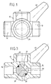
- a housing 10 has a cylindrical through hole 12 to which two outlet openings 14, 16 and an inlet opening 18 each connect via radial channels 20.
- the three openings 14, 16, 18 are aligned radially, their respective axes intersect in the longitudinal axis 22 of the housing 10.
- the two outlet openings 14, 16 lie diametrically opposite one another, that is to say are arranged coaxially.
- the inlet opening 18 extends perpendicular to it. The latter has an internal thread, while the two outlet openings 14, 16 are assigned outlet threads.
- a valve piston 24 is rotatably arranged, which is predominantly circular-cylindrical contoured, but has a flat 27 in the axial region of the bores 20, which extends approximately over a circumferential angle of 150 °. This flattening 27 creates a circular segment-shaped cavity which connects the radial channel of the inlet opening 18 with that of one of the two outlet openings 14, 16 in certain rotational positions.
- the valve piston 24 can be rotated through 90 °.
- the two rotational end positions are defined by stops, namely that the valve piston 24 has an annular flange 26 at its end shown on the right in FIG a cylindrical projection 28 of the housing 10 is received and on which extends axially inward a projection 30 which extends into a circumferential recess of the housing 10, the circumferential angle of which is equal to the desired angle of rotation of the valve piston 24 plus twice the width of the projection 30.
- the valve piston 24 is provided with two axially spaced annular grooves 32, 34 which accommodate the axial area of the bores 20 between them.
- the two annular grooves 32, 34 are connected to one another by two axial grooves 36.
- a basket seal 38 which seals the axial area of the radial channels 20 to the outside and between two peripheral areas.
- the annular piston 24 is rotatably connected to a hand lever 40, but is detachably connected.
- the hand lever 40 has an annular collar 42 which is rotatably mounted in a hollow cylindrical extension 44 of the annular chamber 12.
- a shoulder 46 of the valve piston 24 engages in the annular collar 42, which is arranged coaxially to the latter and has a number of axial webs 48 arranged at close intervals on its circumference.
- the inner circumference of the collar 42 of the actuating lever 40 is complementary.
- the actuating lever 40 can thus be adjusted in fine steps with respect to its relative rotational position to the valve piston 24. For this purpose, it is only necessary to pull the actuating lever 40 axially out of the housing 10 and to insert it again in a suitable new rotational position.
- the axial securing of the actuating lever 40 on the valve piston 24 is achieved by means of a screw 50 which passes through a central hole in the actuating lever 40 and is screwed into a coaxial screw hole in the shoulder 46.
- the head of the screw 50 is located in an end recess 52 of the actuating lever 40, which can be closed by means of a cover cap.
- the actuating lever 40 would collide with the outlet in any case if the thread attachment is only short.
- the operating lever 40 can e.g. rotated by 180 °, attach to the valve piston 24 so that it points to the bottom left instead of the position shown to the top right. The pivoting range of the hand lever 40 is then below the housing 10.
- the shower water connection support is on the top of the mixer tap.
- the housing 10 is then installed, so to speak, overhead.
- the downwardly extending actuating lever 40 can collide with the fitting, which can be avoided by repositioning the manual actuating lever 40. Because of the fineness of the axial toothing between the shoulder 46 of the valve piston 24 and the actuating lever 40, the relative rotational position of the actuating lever 40 can be placed in the most favorable range in each case, so that a high level of user friendliness is achieved.
Landscapes
- Engineering & Computer Science (AREA)
- General Engineering & Computer Science (AREA)
- Mechanical Engineering (AREA)
- Health & Medical Sciences (AREA)
- Life Sciences & Earth Sciences (AREA)
- Hydrology & Water Resources (AREA)
- Public Health (AREA)
- Water Supply & Treatment (AREA)
- Multiple-Way Valves (AREA)
- Mechanically-Actuated Valves (AREA)
- Superheterodyne Receivers (AREA)
Applications Claiming Priority (2)
| Application Number | Priority Date | Filing Date | Title |
|---|---|---|---|
| DE29513138U | 1995-08-16 | ||
| DE29513138U DE29513138U1 (de) | 1995-08-16 | 1995-08-16 | Umschaltweiche zum Anschluß an Wasserhähne und Mischarmaturen |
Publications (2)
| Publication Number | Publication Date |
|---|---|
| EP0762029A2 true EP0762029A2 (fr) | 1997-03-12 |
| EP0762029A3 EP0762029A3 (fr) | 1997-12-03 |
Family
ID=8011820
Family Applications (1)
| Application Number | Title | Priority Date | Filing Date |
|---|---|---|---|
| EP96112918A Withdrawn EP0762029A3 (fr) | 1995-08-16 | 1996-08-10 | Soupape d'inversion pour connexion à conduites d'eau dans le domaine domestique et sanitaire |
Country Status (4)
| Country | Link |
|---|---|
| EP (1) | EP0762029A3 (fr) |
| JP (1) | JPH09112738A (fr) |
| CA (1) | CA2183394A1 (fr) |
| DE (1) | DE29513138U1 (fr) |
Cited By (4)
| Publication number | Priority date | Publication date | Assignee | Title |
|---|---|---|---|---|
| DE19823423A1 (de) * | 1998-05-26 | 1999-12-09 | Kludi Armaturen Scheffer Vertr | Befestigungselement für einen Ventilgriff |
| WO2011134628A1 (fr) * | 2010-04-28 | 2011-11-03 | Grohe Ag | Robinet mélangeur sanitaire, en particulier pour une douche |
| EP2792854A1 (fr) * | 2013-04-16 | 2014-10-22 | Bell Helicopter Textron Inc. | Soupape de vidange de carburant pour turbine |
| DE102016219081B3 (de) | 2016-09-30 | 2018-03-29 | Melag Medizintechnik Ohg | Ventilanordnung und damit ausgestattete fluidführende Vorrichtung |
Families Citing this family (2)
| Publication number | Priority date | Publication date | Assignee | Title |
|---|---|---|---|---|
| IT1402392B1 (it) * | 2010-10-08 | 2013-09-04 | Bollo | Dispositivo deviatore, particolarmente per apparecchi sanitari quali docce, vasche e simili. |
| JP7097106B1 (ja) * | 2021-01-13 | 2022-07-07 | 源美股▲分▼有限公司 | 水栓用多方分岐カプラ |
Family Cites Families (10)
| Publication number | Priority date | Publication date | Assignee | Title |
|---|---|---|---|---|
| US1609964A (en) * | 1925-01-19 | 1926-12-07 | Frank M Roby | Three-way valve |
| US2271075A (en) * | 1940-08-16 | 1942-01-27 | Ingersoll Rand Co | Connecting device |
| DE1213683B (de) * | 1962-01-29 | 1966-03-31 | Schloesser Kg Johann | Regulierhahn fuer Einrohr-Heizungsanlagen |
| DE2355582A1 (de) * | 1973-11-07 | 1975-05-15 | Erwin Damrau | Badebank fuer badewannen |
| JPS5545943U (fr) * | 1978-09-22 | 1980-03-26 | ||
| US4655252A (en) * | 1980-03-24 | 1987-04-07 | Krumhansl Mark U | Valves |
| DE3037804C2 (de) * | 1980-10-07 | 1982-11-18 | Friedrich Grohe Armaturenfabrik Gmbh & Co, 5870 Hemer | Mischventil |
| US4445529A (en) * | 1981-08-31 | 1984-05-01 | Speakman Company | Adjustable valve handle |
| JPS63501841A (ja) * | 1985-12-20 | 1988-07-28 | ジ・アップジョン・カンパニ− | 組織プラスミノ−ゲンアクチベ−タ−(tpa)同族体 |
| US5165456A (en) * | 1991-04-16 | 1992-11-24 | Woolman Richard F | Diverter apparatus and method for saving fresh water |
-
1995
- 1995-08-16 DE DE29513138U patent/DE29513138U1/de not_active Expired - Lifetime
-
1996
- 1996-08-10 EP EP96112918A patent/EP0762029A3/fr not_active Withdrawn
- 1996-08-15 CA CA 2183394 patent/CA2183394A1/fr not_active Abandoned
- 1996-08-16 JP JP23476096A patent/JPH09112738A/ja active Pending
Cited By (6)
| Publication number | Priority date | Publication date | Assignee | Title |
|---|---|---|---|---|
| DE19823423A1 (de) * | 1998-05-26 | 1999-12-09 | Kludi Armaturen Scheffer Vertr | Befestigungselement für einen Ventilgriff |
| DE19823423B4 (de) * | 1998-05-26 | 2006-06-01 | Kludi Gmbh & Co.Kg | Befestigungselement für einen Ventilgriff |
| WO2011134628A1 (fr) * | 2010-04-28 | 2011-11-03 | Grohe Ag | Robinet mélangeur sanitaire, en particulier pour une douche |
| EP2792854A1 (fr) * | 2013-04-16 | 2014-10-22 | Bell Helicopter Textron Inc. | Soupape de vidange de carburant pour turbine |
| US9086016B2 (en) | 2013-04-16 | 2015-07-21 | Bell Helicopter Textron Inc. | Fuel drain valve for a turbine engine |
| DE102016219081B3 (de) | 2016-09-30 | 2018-03-29 | Melag Medizintechnik Ohg | Ventilanordnung und damit ausgestattete fluidführende Vorrichtung |
Also Published As
| Publication number | Publication date |
|---|---|
| CA2183394A1 (fr) | 1997-02-17 |
| EP0762029A3 (fr) | 1997-12-03 |
| JPH09112738A (ja) | 1997-05-02 |
| DE29513138U1 (de) | 1995-10-12 |
Similar Documents
| Publication | Publication Date | Title |
|---|---|---|
| EP1261824B1 (fr) | Robinet sanitaire, en particulier mitigeur menager | |
| DE1550060B2 (de) | Mischventil mit gekapselten steuerungsteilen | |
| DE202013103517U1 (de) | Befestigungsanordnung für einen Wasserhahn | |
| DE2904131C3 (de) | Mischventil für Flüssigkeiten | |
| DE3222004A1 (de) | Vorrichtung zum ausloesen des wasserauslaufes bei einem wasserhahn | |
| EP0043076B1 (fr) | Robinet mélangeur pour liquides | |
| EP3074676B1 (fr) | Robinetterie sanitaire | |
| DE2311840C2 (de) | Mischventil für zwei Fluidströmungen | |
| EP0606419A1 (fr) | Partie superieure de soupape. | |
| DE29513138U1 (de) | Umschaltweiche zum Anschluß an Wasserhähne und Mischarmaturen | |
| DE3700927C2 (fr) | ||
| EP0804970B1 (fr) | Pistolet de pulvérisation à main pour appareil de nettoyage haute pression | |
| DE9101627U1 (de) | Über-Kopf-gesteuerte Einloch-Einhebelmischbatterie | |
| DE2907565C2 (de) | Kombinierte Selbstschluß- und Mischarmatur | |
| DE2601349C2 (de) | Einrichtung für Wasserrohrleitungen mit mindestens zwei Absperrorganen oder mindestens einem Absperrorgan und mindestens einem Filter | |
| DE4235723A1 (de) | Mehrwege-Kugelhahn | |
| EP1285621B1 (fr) | Pomme de douche, en particulier pour une douche latérale | |
| DE9309418U1 (de) | Hebelmischarmatur | |
| DE2616898C3 (de) | Steuervorrichtung für Mischventile | |
| DE2634721A1 (de) | Hydraulisches dreiwegeventil, insbesondere wasseranschluss fuer mund- und/ oder hautmassage- bzw. hautreinigungsduschen | |
| DE3509295A1 (de) | Mischarmatur | |
| DE3510908A1 (de) | Einloch-mischbatterie mit ventilgesteuertem kaltwasser-geraeteanschluss | |
| WO2026067961A1 (fr) | Élément de fermeture pour fermer une ouverture de sortie dans la surface inférieure d'un lavabo | |
| DE8607840U1 (de) | Einhand-Kupplung mit Sitzventil, für Schläuche und/oder Rohre | |
| DE2602497A1 (de) | Hydraulisches dreiwegeventil, insbesondere wasseranschluss fuer mund- und/ oder hautmassage- bzw. hautreinigungsdusche |
Legal Events
| Date | Code | Title | Description |
|---|---|---|---|
| PUAI | Public reference made under article 153(3) epc to a published international application that has entered the european phase |
Free format text: ORIGINAL CODE: 0009012 |
|
| AK | Designated contracting states |
Kind code of ref document: A2 Designated state(s): AT BE CH DE DK ES FI FR GB GR IE IT LI LU NL PT SE |
|
| PUAL | Search report despatched |
Free format text: ORIGINAL CODE: 0009013 |
|
| AK | Designated contracting states |
Kind code of ref document: A3 Designated state(s): AT BE CH DE DK ES FI FR GB GR IE IT LI LU NL PT SE |
|
| STAA | Information on the status of an ep patent application or granted ep patent |
Free format text: STATUS: THE APPLICATION IS DEEMED TO BE WITHDRAWN |
|
| 18D | Application deemed to be withdrawn |
Effective date: 19980604 |