EP0762095A1 - Tauchspulen-Geber mit Membranstützkörper - Google Patents
Tauchspulen-Geber mit Membranstützkörper Download PDFInfo
- Publication number
- EP0762095A1 EP0762095A1 EP96111273A EP96111273A EP0762095A1 EP 0762095 A1 EP0762095 A1 EP 0762095A1 EP 96111273 A EP96111273 A EP 96111273A EP 96111273 A EP96111273 A EP 96111273A EP 0762095 A1 EP0762095 A1 EP 0762095A1
- Authority
- EP
- European Patent Office
- Prior art keywords
- membrane
- support body
- moving coil
- contour
- diaphragm
- Prior art date
- Legal status (The legal status is an assumption and is not a legal conclusion. Google has not performed a legal analysis and makes no representation as to the accuracy of the status listed.)
- Granted
Links
- 239000012528 membrane Substances 0.000 claims abstract description 92
- 230000005520 electrodynamics Effects 0.000 claims abstract description 17
- 238000002347 injection Methods 0.000 claims abstract description 7
- 239000007924 injection Substances 0.000 claims abstract description 7
- 239000004753 textile Substances 0.000 claims abstract description 7
- 239000011324 bead Substances 0.000 claims description 20
- 238000005259 measurement Methods 0.000 claims description 17
- 238000009747 press moulding Methods 0.000 abstract 1
- 239000004033 plastic Substances 0.000 description 3
- 239000000428 dust Substances 0.000 description 2
- 239000000835 fiber Substances 0.000 description 2
- 239000000463 material Substances 0.000 description 2
- 238000000034 method Methods 0.000 description 2
- 238000007493 shaping process Methods 0.000 description 2
- BGPVFRJUHWVFKM-UHFFFAOYSA-N N1=C2C=CC=CC2=[N+]([O-])C1(CC1)CCC21N=C1C=CC=CC1=[N+]2[O-] Chemical compound N1=C2C=CC=CC2=[N+]([O-])C1(CC1)CCC21N=C1C=CC=CC1=[N+]2[O-] BGPVFRJUHWVFKM-UHFFFAOYSA-N 0.000 description 1
- 238000009825 accumulation Methods 0.000 description 1
- 238000005452 bending Methods 0.000 description 1
- 238000005352 clarification Methods 0.000 description 1
- 230000000994 depressogenic effect Effects 0.000 description 1
- 238000006073 displacement reaction Methods 0.000 description 1
- 210000004905 finger nail Anatomy 0.000 description 1
- 238000007373 indentation Methods 0.000 description 1
- 238000004519 manufacturing process Methods 0.000 description 1
- 239000002184 metal Substances 0.000 description 1
- 230000002093 peripheral effect Effects 0.000 description 1
- 239000004417 polycarbonate Substances 0.000 description 1
- 229920000515 polycarbonate Polymers 0.000 description 1
Images


Classifications
-
- G—PHYSICS
- G01—MEASURING; TESTING
- G01L—MEASURING FORCE, STRESS, TORQUE, WORK, MECHANICAL POWER, MECHANICAL EFFICIENCY, OR FLUID PRESSURE
- G01L5/00—Apparatus for, or methods of, measuring force, work, mechanical power, or torque, specially adapted for specific purposes
- G01L5/04—Apparatus for, or methods of, measuring force, work, mechanical power, or torque, specially adapted for specific purposes for measuring tension in flexible members, e.g. ropes, cables, wires, threads, belts or bands
- G01L5/10—Apparatus for, or methods of, measuring force, work, mechanical power, or torque, specially adapted for specific purposes for measuring tension in flexible members, e.g. ropes, cables, wires, threads, belts or bands using electrical means
- G01L5/108—Apparatus for, or methods of, measuring force, work, mechanical power, or torque, specially adapted for specific purposes for measuring tension in flexible members, e.g. ropes, cables, wires, threads, belts or bands using electrical means for measuring a reaction force applied on a single support, e.g. a glider
-
- B—PERFORMING OPERATIONS; TRANSPORTING
- B65—CONVEYING; PACKING; STORING; HANDLING THIN OR FILAMENTARY MATERIAL
- B65H—HANDLING THIN OR FILAMENTARY MATERIAL, e.g. SHEETS, WEBS, CABLES
- B65H59/00—Adjusting or controlling tension in filamentary material, e.g. for preventing snarling; Applications of tension indicators
- B65H59/40—Applications of tension indicators
-
- D—TEXTILES; PAPER
- D01—NATURAL OR MAN-MADE THREADS OR FIBRES; SPINNING
- D01H—SPINNING OR TWISTING
- D01H13/00—Other common constructional features, details or accessories
- D01H13/26—Arrangements facilitating the inspection or testing of yarns or the like in connection with spinning or twisting
-
- G—PHYSICS
- G01—MEASURING; TESTING
- G01D—MEASURING NOT SPECIALLY ADAPTED FOR A SPECIFIC VARIABLE; ARRANGEMENTS FOR MEASURING TWO OR MORE VARIABLES NOT COVERED IN A SINGLE OTHER SUBCLASS; TARIFF METERING APPARATUS; MEASURING OR TESTING NOT OTHERWISE PROVIDED FOR
- G01D5/00—Mechanical means for transferring the output of a sensing member; Means for converting the output of a sensing member to another variable where the form or nature of the sensing member does not constrain the means for converting; Transducers not specially adapted for a specific variable
- G01D5/12—Mechanical means for transferring the output of a sensing member; Means for converting the output of a sensing member to another variable where the form or nature of the sensing member does not constrain the means for converting; Transducers not specially adapted for a specific variable using electric or magnetic means
- G01D5/14—Mechanical means for transferring the output of a sensing member; Means for converting the output of a sensing member to another variable where the form or nature of the sensing member does not constrain the means for converting; Transducers not specially adapted for a specific variable using electric or magnetic means influencing the magnitude of a current or voltage
- G01D5/20—Mechanical means for transferring the output of a sensing member; Means for converting the output of a sensing member to another variable where the form or nature of the sensing member does not constrain the means for converting; Transducers not specially adapted for a specific variable using electric or magnetic means influencing the magnitude of a current or voltage by varying inductance, e.g. by a movable armature
- G01D5/2006—Mechanical means for transferring the output of a sensing member; Means for converting the output of a sensing member to another variable where the form or nature of the sensing member does not constrain the means for converting; Transducers not specially adapted for a specific variable using electric or magnetic means influencing the magnitude of a current or voltage by varying inductance, e.g. by a movable armature by influencing the self-induction of one or more coils
- G01D5/2033—Mechanical means for transferring the output of a sensing member; Means for converting the output of a sensing member to another variable where the form or nature of the sensing member does not constrain the means for converting; Transducers not specially adapted for a specific variable using electric or magnetic means influencing the magnitude of a current or voltage by varying inductance, e.g. by a movable armature by influencing the self-induction of one or more coils controlling the saturation of a magnetic circuit by means of a movable element, e.g. a magnet
-
- G—PHYSICS
- G01—MEASURING; TESTING
- G01L—MEASURING FORCE, STRESS, TORQUE, WORK, MECHANICAL POWER, MECHANICAL EFFICIENCY, OR FLUID PRESSURE
- G01L5/00—Apparatus for, or methods of, measuring force, work, mechanical power, or torque, specially adapted for specific purposes
- G01L5/04—Apparatus for, or methods of, measuring force, work, mechanical power, or torque, specially adapted for specific purposes for measuring tension in flexible members, e.g. ropes, cables, wires, threads, belts or bands
- G01L5/10—Apparatus for, or methods of, measuring force, work, mechanical power, or torque, specially adapted for specific purposes for measuring tension in flexible members, e.g. ropes, cables, wires, threads, belts or bands using electrical means
-
- B—PERFORMING OPERATIONS; TRANSPORTING
- B65—CONVEYING; PACKING; STORING; HANDLING THIN OR FILAMENTARY MATERIAL
- B65H—HANDLING THIN OR FILAMENTARY MATERIAL, e.g. SHEETS, WEBS, CABLES
- B65H2701/00—Handled material; Storage means
- B65H2701/30—Handled filamentary material
- B65H2701/31—Textiles threads or artificial strands of filaments
Definitions
- the invention relates to an electrodynamic moving coil sensor according to the preamble of the first claim.
- Electrodynamic moving coil sensors are used, for example, as thread tension sensors.
- EP 0 531 753 B1 discloses such a device for determining the thread tension of threads which are wound on bobbins on textile machines.
- Electrodynamic plunger sensors are particularly suitable for measuring the thread tension on fast-running threads, since they can also be used to determine high-frequency fluctuations in thread tension.
- the moving coil is advantageously mounted by means of at least one membrane.
- An example of a moving coil mounting by means of a membrane is known from an exemplary embodiment of the above-mentioned EP 0 531 753 B1.
- the membranes are usually disc-shaped. To generate a linear force-displacement characteristic curve, they can be provided with concentrically arranged beads or other contours.
- the moving coil is usually centered on an axis, which in turn is guided centrally through the membrane and is firmly connected to it.
- the membranes are very thin, for example, under threads, for example under threads, for example less than a tenth of a millimeter, and are therefore sensitive to improper treatment. If, for example, on a membrane with concentrically arranged beads, one of the beads is pressed in locally from its raised side, As a rule, the elasticity of the membrane is not sufficient to undo this error. The deformation remains and thus prevents the membrane from vibrating as intended.
- the object of the present invention is to maintain the functionality of membranes on which the moving coils of electrodynamic moving coil sensors are mounted.
- the support body according to the invention behind the membrane effectively prevents the membrane from deforming. Because the side of the support body facing the membrane has a contour which is essentially adapted to the shape of the contour of the side of the membrane facing the support body with a measurement-related maximum possible deflection towards the support body, it is not possible to deform the membrane in this way that there is a permanent deformation that affects the function of the membrane.
- the distance between the membrane and the support body is at least so large that the membrane does not just touch the support body during its measurement-related maximum deflection. This will ensure that the Plunger coil transducer is not hindered, on the other hand, any stress on the membrane beyond this maximum deflection is intercepted by the support body and thus prevented.
- the distance between the support body and the membrane at its maximum possible deflection due to measurement is, for example, between 0.3 and 0.1 mm.
- the distance between the membrane and the support body during the intended measurement processes is also chosen to be so large that the membrane, which vibrates during the high-frequency measurements, does not touch the support body. Such touches would impair the measuring process and falsify the measuring results.
- the contour of the support body is shaped accordingly in its measurement-related maximum possible deflection towards the support body, so that a measurement-related maximum deflection of the membrane between the contour of the membrane and the contour of the support body is a there is an essentially constant distance.
- the minimum, constant distance prevents any deflection of the membrane beyond the intended use, without causing permanent damage to the membrane.
- Beads are particularly sensitive to local deformation. A depressed bead significantly affects the function of the membrane and can even make it impossible. By shaping a counter-contour of the beads in the support body, the membrane completely rests against the support body in the event of a deformation that is not in accordance with the intended purpose.
- the support body can be manufactured as an injection molded or die cast part. Injection molded bodies made of plastic or die-cast bodies made of metal can be produced in large quantities, true to size and cheaply.
- the required contour is only to be introduced once into the shaping tool.
- the support body and the membrane can be combined into one structural unit. This eliminates the need for centering when inserting the membrane in the moving coil sensor and the membrane is optimally protected against improper handling when the push button carrying the moving coil is glued to the membrane.
- Fig. 1 an electrodynamic plunger sensor is shown in section, which is used as a thread tension sensor in a textile machine. Only the features contributing to the understanding of the invention are shown and explained.
- the thread tension sensor 1 is installed in a textile machine, not shown here, in a housing, the contour 2 of which is indicated here.
- the housing 2 encloses the Thread tension sensor except for the exposed front side, which faces the measurement object, here a running thread 3.
- the membrane is not covered because dust and fiber fly could settle between a cover and the membrane, which would hinder the function of the membrane.
- the pot-like housing 4 is part of the magnet system.
- a permanent magnet 5, which carries a pole disk 6, is arranged centrally in the interior of the housing 4.
- the pole disc 6 is surrounded by the moving coil 7 in a ring.
- the moving coil 7 is held by a coil carrier 8, which is mounted centrally on the one hand in a membrane 9 which, glued to a ring 10, closes the housing 4 on the side facing away from the thread 3.
- a control device is known, for example, from EP 0 531 753 B1.
- the coil carrier 8 carries a tube 12 which is guided through the central bore 13 of the pole disk and the permanent magnet and of the housing 4 and protrudes from the housing 4. At its end it carries the button 14 over which the thread 3 runs.
- the button 14 is connected to a circular membrane 15 so that it is arranged centrally in the membrane center 15 m.
- the membrane 15 is glued with its outer peripheral edge 15r onto the annular end face 16s of the support body 16 according to the invention.
- the shape of the membranes 9 and 15 is identical.
- Each of the two membranes 9 and 15 has three beads 17a, 17b and 17c and 17d, 17e and 17f. They are of the same height and form concentric rings.
- the membranes are arranged so that the beads face outwards.
- the support body 16 has on its side facing the membrane 15 a contour 18 which essentially follows the shape of the contour 19 of the side of the membrane facing the support body 16.
- the contour 18 of the support body 16 has the task of supporting the membrane 15, in particular in the event of accidental point loads on the beads. This prevents the beads from being pressed in. Precise punctual loading of the beads can lead to kinks in certain materials, for example polycarbonates, which destroy the structure of the membrane surface and thus make it unusable.
- the support body also prevents large-area plastic deformations and deformations that go beyond the intended deflections during thread tension testing. Even if there are only elastically deformable impressions, the membrane can still be unusable if it is pressed in from the accessible front, but is no longer accessible from the rear, in order to push the deformation out again.
- the button 14 In order for the electrodynamic moving coil transducer to be able to perform its function, the button 14 must be able to move back and forth. The membranes must therefore be able to vibrate freely in the area of the measured values to be recorded.
- FIG. 1 shows the position of the membrane 15 in its undeflected position.
- the measurement-related maximum deflection of the membrane is shown by the contour line 21 shown in dashed lines in FIG. 1.
- the membrane 15 must not yet come into contact with the contour 18 of the support body 16.
- the distance between the membrane 15 and the contour 18 of the support body 16 should advantageously be at least 0.1 millimeters. In the present exemplary embodiment, the distances between the membrane 15 and the contour 18 of the support body 16 are over for clarification the actual distance ratio is shown enlarged.
- the contour 18 of the support body 16 is essentially adapted to the contour 19 of the diaphragm 15 and takes into account the measurement-related maximum deflection 21 by retreating the contour 18 towards the center 15 m of the diaphragm.
- the support body 16 can consist of an injection molded part, for example of a plastic, since the complicated surface shape of the contour 18 can be reproduced simply and cheaply on an injection molded part. If the membrane 15 is already glued to the edge of this injection molded part before the electrodynamic moving coil sensor is mounted, the membrane 15 is already advantageously protected against damage when the button 14 is attached and during the subsequent assembly.
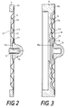
- FIG. 2 shows an enlarged membrane 15 compared to FIG. 1.
- the bead 17b has been pressed in locally, which has caused a deformation point 22.
- Such deformations can be caused, for example, by fingernails or screwdrivers and, when the bead is pressed in, often also lead to kinks 23, which cause the material to be destroyed.
- the membrane is inoperable. Since the membrane yields when an object hits it, unless it already destroys the membrane due to its sharp contour, the support body according to the invention offers reliable protection against damage, since it catches and supports the yielding membrane. This prevents further bending or local deformation, which ultimately leads to a deformation point.
- FIG. 3 shows, as an enlarged detail of FIG. 1, the membrane 15 combined with the support body 16 to form a ready-to-install structural unit.
- the button 14 has already been stuck in the center 15m of the membrane 15.
- FIGS. 1 and 3 An ideal course of the contour 18 of the support body 16 is shown in FIGS. 1 and 3.
- the function of protecting the beads is already fulfilled by a disc of graduated thickness with two concentric, graduated webs, which are each arranged behind the two outermost, most vulnerable beads.
- An exemplary embodiment is shown in FIG. 4.
- the membrane 15 is glued to the end face 110s of a ring 110 which is identical in size and shape to the ring 10 to which the membrane 9 is glued.
- a disc 116 is glued to the end face of the bottom of the pot-shaped housing 4 as a support body.
- the disc 116 is centered on its circumference by the ring 110.
- the disk On its contour 118 facing the membrane 15, the disk has two zones 118a and 118b of different thicknesses, which take into account the contour course of the membrane 15 during a maximum deflection caused by the measurement.
- annular strips 118x and 118y To support the beads 17a and 17b, which are most at risk from damage and indentation, there are annular strips 118x and 118y, which also have a graduated height in terms of the measurement-related maximum deflection.
- the advantage of the support body 16 according to the previous embodiment over the support body 116 is that there the membrane 15 can lie flat against the support body, while in the support body 116 the membrane is only supported in a ring shape in the bead peaks and valleys.
- the support body 116 does not require any complicated Forming and is therefore easier to manufacture, which is particularly advantageous for small quantities.
Landscapes
- Physics & Mathematics (AREA)
- General Physics & Mathematics (AREA)
- Engineering & Computer Science (AREA)
- Mechanical Engineering (AREA)
- Textile Engineering (AREA)
- Force Measurement Appropriate To Specific Purposes (AREA)
- Transmission And Conversion Of Sensor Element Output (AREA)
- Measuring Fluid Pressure (AREA)
- Treatment Of Fiber Materials (AREA)
Abstract
Description
- Die Erfindung betrifft einen elektrodynamischen Tauchspulen-Geber nach dem Oberbegriff des ersten Anspruchs.
- Elektrodynamische Tauchspulen-Geber werden beispielsweise als Fadenzugkraftsensoren eingesetzt. Aus der EP 0 531 753 B1 ist eine derartige Vorrichtung zur Bestimmung der Fadenzugkraft von Fäden bekannt, die an Textilmaschinen auf Spulen gewickelt werden. Elektrodynamische Tauchspulen-Geber sind zur Messung der Fadenzugkraft an schnell laufenden Fäden besonders geeignet, da mit ihnen auch hochfrequente Fadenzugkraftschwankungen ermittelt werden können.
- Um hochfrequente Schwankungen des Drucks auf den Meßfühler und damit auf die Tauchspule möglichst trägheitslos weitergeben zu können, wird die Tauchspule vorteilhaft mittels mindestens einer Membrane gelagert. Ein Beispiel für eine Tauchspulen-Lagerung mittels einer Membrane ist aus einem Ausführungsbeispiel der oben genannten EP 0 531 753 B1 bekannt. Die Membranen sind in der Regel scheibenförmig. Zur Erzeugung einer linearen Kraft-Weg-Kennlinie können sie mit konzentrisch angeordneten Sicken oder anderen Konturen versehen sein. Die Tauchspule sitzt in der Regel zentrisch auf einer Achse, die wiederum zentrisch durch die Membrane geführt wird und mit dieser fest verbunden ist.
- Wegen der geringen Massen und der geringen Größe der Tauchspulen-Geber sind bei den Kräften, wie sie beispielsweise an zu spulenden Fäden auftreten, die Membranen sehr dünn, beispielsweise unter einem zehntel Millimeter, und deshalb gegen unsachgemäße Behandlung empfindlich. Wird beispielsweise an einer Membrane mit konzentrisch angeordneten Sicken eine der Sicken von ihrer erhabenen Seite her örtlich eingedrückt, reicht in der Regel die Elastizität der Membrane nicht aus, um diesen Fehler rückgängig zu machen. Die Verformung bleibt und verhindert damit eine bestimmungsgemäße Möglichkeit des Schwingens der Membrane.
- Eine Abdeckung der Membranen zu ihrem Schutz ist nicht immer möglich. Insbesondere bei einem Einsatz in Textilmaschinen ist eine Abdeckung einer einen Taster am laufenden Faden tragende Membrane nicht möglich, da sich zwischen Membrane und Abdeckung aufgrund des Faserflugs Staubansammlungen bilden würden, welche die Funktion der Membrane beeinträchtigen.
- Aufgabe der vorliegenden Erfindung ist es, die Funktionsfähigkeit von Membranen, auf welchen die Tauchspulen von elektrodynamischen Tauchspulen-Gebern gelagert sind, zu erhalten.
- Die Lösung der Aufgabe erfolgt erfindungsgemäß mit Hilfe der kennzeichnenden Merkmale des ersten Anspruchs. Weitere vorteilhafte Ausgestaltungen der Erfindung werden in den Unteransprüchen beansprucht.
- Der erfindungsgemäße Stützkörper hinter der Membrane verhindert wirkungsvoll eine Deformierung der Membrane. Dadurch, daß die der Membrane zugewandte Seite des Stützkörpers eine Kontur aufweist, die im wesentlichen dem Verlauf der Kontur der dem Stützkörper zugewandten Seite der Membrane bei einer meßbedingten maximal möglichen Auslenkung zum Stützkörper hin angepaßt ist, ist es nicht möglich, die Membrane so zu verformen, daß eine bleibende, die Funktion der Membrane beeinträchtigende Deformierung entsteht.
- Der Abstand zwischen der Membrane und dem Stützkörper ist mindestens so groß, daß die Membrane bei ihrer meßbedingten maximalen Auslenkung zum Stützkörper hin diesen gerade noch nicht berührt. Dadurch wird eine bestimmungsgemäße Funktion des Tauchspulen-Gebers nicht behindert, andererseits wird jede über diese maximale Auslenkung hinausgehende Beanspruchung der Membrane durch den Stützkörper abgefangen und damit verhindert. Der Abstand zwischen dem Stützkörper und der Membrane bei ihrer meßbedingten maximalen möglichen Auslenkung liegt beispielsweise zwischen 0,3 und 0,1 mm. Der Abstand zwischen Membrane und Stützkörper während der bestimmungsgemäßen Meßvorgänge ist außerdem so groß gewählt, daß die Membrane, die während der hochfrequenten Messungen in Schwingung gerät, den Stützkörper nicht berührt. Solche Berührungen würden dem Meßvorgang beeinträchtigen und die Meßergebnisse verfälschen.
- Um einen optimalen Schutz der Membranen zu erreichen, ist die Kontur des Stützkörpers der Kontur der Membrane in ihrer meßbedingten maximal möglichen Auslenkung zum Stützkörper hin entsprechend ausgeformt, so daß bei der meßbedingten maximalen Auslenkung der Membrane zwischen der Kontur der Membrane und der Kontur des Stützkörpers ein im wesentlichen konstanter Abstand herrscht. Der minimale, konstante Abstand verhindert, daß jede über den bestimmungsgemäßen Gebrauch hinausgehende Auslenkung der Membrane verhindert wird, ohne daß bleibende Schäden an der Membrane entstehen.
- Das ist besonders wichtig bei Membranen, die durch konzentrisch angeordnete Sicken versteift werden. Sicken sind besonders empfindlich gegen örtliche Verformungen. Eine eingedrückte Sicke beeinträcht die Funktion der Membrane erheblich und kann sie sogar unmöglich machen. Durch die Ausformung einer Gegenkontur der Sicken in dem Stützkörper legt sich die Membrane bei einer nicht bestimmungsgemäßen Verformung vollständig an den Stützkörper an.
- In einer vorteilhaften Ausgestaltung der Erfindung kann der Stützkörper als Spritzguß- oder Druckgußteil gefertigt sein. Spritzgußkörper aus Kunststoff oder Druckgußkörper aus Metall, sind in hohen Stückzahlen maßhaltig und billig herzustellen.
- Die erforderliche Kontur ist im Negativ nur einmal in das formgebende Werkzeug einzubringen.
- In einer weiteren Ausgestaltung der Erfindung können der Stützkörper und die Membrane zu einer Baueinheit zusammengefaßt sein. Damit entfallen Zentrierungsarbeiten beim Einsetzen der Membrane in den Tauchspulen-Geber und die Membrane ist beim Verkleben des die Tauchspule tragenden Tasters mit der Membrane optimal gegen unsachgemäße Behandlung geschützt.
- Anhand eines Ausführungsbeispiels wird die Erfindung näher erläutert.
- Es zeigen:
- Fig. 1 eine schematische Darstellung eines elektrodynamischen Tauchspulen-Gebers, der als Fadenzugkraft-Sensor in einer Textilmaschine eingesetzt wird, vergrößert und im Schnitt,
- Fig. 2 eine beschädigte Membrane mit einer eingedrückten Sicke, im Schnitt,
- Fig. 3 den Stützkörper mit der Membrane als Baueinheit, im Schnitt, und
- Fig. 4 ein weiteres Ausführungsbeispiel eines Stützkörpers, im Schnitt.
- In Fig. 1 ist ein elektrodynamischer Tauchspulen-Geber im Schnitt dargestellt, der als Fadenzugkraftsensor in einer Textilmaschine eingesetzt wird. Es sind nur die zum Verständnis der Erfindung beitragenden Merkmale dargestellt und erläutert.
- Der Fadenzugkraftsensor 1 ist in einer hier nicht dargestellten Textilmaschine in einem Gehäuse eingebaut, dessen Kontur 2 hier angedeutet ist. Das Gehäuse 2 umschließt den Fadenzugkraftsensor bis auf die freiliegende Frontseite, die dem Meßobjekt, hier einem laufenden Faden 3, zugewandt ist. Die Membrane ist nicht abgedeckt, weil sich zwischen einer Abdeckung und der Membrane Staub und Faserflug setzen könnte, der die Funktion der Membrane behindern würde.
- Das topfartige Gehäuse 4 ist Bestandteil des Magnetsystems. Im Innern des Gehäuses 4 ist zentrisch angeordnet ein Permanentmagnet 5, der eine Polscheibe 6 trägt. Die Polscheibe 6 wird von der Tauchspule 7 ringförmig umschlossen. Die Tauchspule 7 wird von einem Spulenträger 8 gehalten, der einerseits zentrisch in einer Membrane 9 gelagert ist, die auf einem Ring 10 geklebt das Gehäuse 4 auf der dem Faden 3 abgewandten Seite verschließt. Mit 11a und 11b sind die Anschlüsse der Tauchspule 7 bezeichnet. Die Anschlüsse der Tauchspule führen zu einer hier nicht dargestellten Steuereinrichtung. Eine solche Steuereinrichtung ist bespielsweise aus der EP 0 531 753 B1 bekannt.
- Der Spulenträger 8 trägt ein Röhrchen 12, das durch die zentrische Bohrung 13 der Polscheibe und des Permanentmagneten sowie des Gehäuses 4 geführt ist und aus dem Gehäuse 4 herausragt. An seinem Ende trägt es den Taster 14, über den der Faden 3 läuft. Der Taster 14 ist mit einer kreisförmigen Membrane 15 so verbunden, daß er zentrisch im Membranenmittelpunkt 15 m angeordnet ist. Die Membrane 15 ist mit ihrem äußeren Umfangsrand 15r auf die ringförmige Stirnfläche 16s des erfindungsgemäßen Stützkörpers 16 geklebt.
- Die Form der Membranen 9 und 15 ist identisch. Jede der beiden Membranen 9 und 15 weist drei Sicken 17a, 17b und 17c sowie 17d, 17e und 17f auf. Sie sind gleich hoch und bilden konzentrische Ringe. Die Membranen sind so angeordnet, daß die Sicken jeweils nach außen weisen.
- Der Stützkörper 16 weist auf seiner der Membrane 15 zugewandten Seite eine Kontur 18 auf, die im wesentlichen dem Verlauf der Kontur 19 der dem Stützkörper 16 zugewandten Seite der Membrane folgt. Die Kontur 18 des Stützkörpers 16 hat die Aufgabe, die Membrane 15 insbesondere bei unbeabsichtigten punktuellen Belastungen der Sicken abzustützen. Dadurch wird ein Eindrücken der Sicken vermieden. Gerade eine punktuelle Belastung der Sicken kann bei bestimmten Materialien, beispielsweise bei Polycarbonaten, zu Knickstellen führen, die die Struktur der Membranoberfläche zerstören und sie damit unbrauchbar machen. Der Stützkörper verhindert weiterhin großflächige plastische Verformungen und über die bestimmungsgemäßen Auslenkungen beim Fadenzugkraftprüfen hinausgehende Verformungen. Selbst wenn es nur zu elastisch rückverformbaren Eindrücken kommt, kann trotzdem die Membrane unbrauchbar werden, wenn sie von der zugänglichen Frontseite her eingedrückt wird, aber von der Rückseite nicht mehr zugängig ist, um die Verformung wieder herauszudrücken.
- Damit der elektrodynamische Tauchspulen-Geber seine Funktion erfüllen kann, muß der Taster 14 eine Hin- und Herbewegung ausführen können. Die Membranen müssen also im Bereich der aufzunehmenden Meßwerte ungehindert schwingen können.
- Im vorliegenden Ausführungsbeispiel drückt der Faden 3 in Pfeilrichtung 20 gegen den Taster 14 Die Fig. 1 gibt die Stellung der Membrane 15 in ihrer nicht ausgelenkten Stellung wieder. Die meßbedingte maximale Auslenkung der Membrane ist durch den gestrichelt wiedergegebenen Konturverlauf 21 in Fig. 1 eingezeichnet. Bei dieser maximalen meßbedingten Auslenkung darf die Membrane 15 noch nicht an die Kontur 18 des Stützkörpers 16 zur Anlage kommen. Der Abstand zwischen der Membrane 15 und der Kontur 18 des Stützkörpers 16 soll vorteilhaft mindestens 0,1 Millimeter betragen. Im vorliegenden Ausführungsbeispiel sind die Abstände zwischen der Membrane 15 und der Kontur 18 des Stützkörpers 16 zur Verdeutlichung über das tatsächliche Abstandsverhältnis hinaus vergrößert dargestellt.
- Wie aus der Fig. 1 ersichtlich, ist die Kontur 18 des Stützkörpers 16 im wesentlichen der Kontur 19 der Membrane 15 angepaßt und trägt der meßbedingten maximalen Auslenkung 21 durch ein Zurückweichen der Kontur 18 zur Mitte 15 m der Membrane hin Rechnung.
- Der Stützkörper 16 kann aus einem Spritzgußteil bestehen, beispielsweise aus einem Kunststoff, da die komplizierte Oberflächenform der Kontur 18 einfach und billig auf einem Spritzgußteil wiedergegeben werden kann. Wird auf den Rand dieses Spritzgußteils bereits die Membrane 15 aufgeklebt, bevor der elektrodynamische Tauchspulen-Geber montiert wird, ist die Membrane 15 beim Ankleben des Tasters 14 und bei der anschließenden Montage bereits vorteilhaft gegen Beschädigungen geschützt.
- Fig. 2 zeigt vergrößert gegenüber Fig. 1 eine beschädigte Membrane 15. Wie ersichtlich, ist die Sicke 17b örtlich eingedrückt worden, was eine Deformationsstelle 22 hervorgerufen hat. Solche Deformationen können beispielsweise durch Fingernägel oder Schraubendreher hervorgerufen werden und führen beim Eindrücken der Sicke häufig auch zu Knickstellen 23, die eine Zerstörung des Materials verursachen. In einem solchen Fall ist die Membrane funktionsunfähig. Da die Membrane beim Auftreffen eines Gegenstandes, sofern er nicht bereits beim Auftreffen aufgrund seiner scharfen Kontur die Membrane zerstört, nachgibt, bietet der erfindungsgemäße Stützkörper einen sicheren Schutz vor Beschädigungen, da er die nachgebende Membrane auffängt und unterstützt. Dadurch wird ein weiteres Durchbiegen oder örtliches Verformen, was schließlich zu einer Deformationsstelle führt, verhindert.
- Fig. 3 zeigt als vergrößerte Einzelheit der Fig. 1 die Membrane 15 mit dem Stützkörper 16 zu einer einbaufertigen Baueinheit vereinigt. Der Taster 14 ist bereits im Zentrum 15m der Membrane 15 aufgeklebt worden.
- In den Fig. 1 und 3 wird ein Idealverlauf der Kontur 18 des Stützkörpers 16 gezeigt. Die Funktion des Schutzes der Sicken erfüllt auch bereits eine Scheibe abgestufter Dicke mit zwei konzentrischen, abgestuften Stegen, die jeweils hinter den zwei äußersten, am stärksten gefährdeten Sicken angeordnet sind. Ein Ausführungsbeispiel ist dafür in Fig. 4 wiedergegeben. Im Ausführungsbeispiel nach Fig. 4 sind alle gegenüber dem vorhergehenden Ausführungsbeispiel unverändert gebliebenen Merkmale mit denselben Bezugsziffern bezeichnet. Im Ausführungsbeispiel nach Fig. 4 ist die Membrane 15 an die Stirnseite 110s eines Rings 110 geklebt, der mit dem Ring 10, an dem die Membrane 9 geklebt ist, in Abmessung und Form identisch ist. An die Stirnfläche des Bodens des topfförmigen Gehäuses 4 ist eine Scheibe 116 als Stützkörper geklebt. Die Scheibe 116 wird auf ihrem Umfang von dem Ring 110 zentriert. Die Scheibe weist auf ihrer, der Membrane 15 zugewandten Kontur 118 zwei Zonen 118a und 118b unterschiedlicher Dicke auf, die dem Konturverlauf der Membrane 15 während einer meßbedingten maximale Auslenkung Rechnung tragen. Zur Abstützung der Sicken 17a und 17b, die am meisten durch Beschädigungen und Eindrücken gefährdet sind, dienen ringförmige Leisten 118x beziehungsweise 118y, die ebenfalls in ihrer Höhe im Hinblick auf die meßbedingte maximale Auslenkung eine abgestufte Höhe aufweisen.
- Der Vorteil des Stützkörpers 16 nach dem vorhergehenden Ausführungsbeispiel gegenüber dem Stützkörper 116 liegt darin, daß sich dort die Membrane 15 flächig an den Stützkörper anlegen kann, während beim Stützkörper 116 die Membrane nur ringförmig in den Sickenbergen und Sickentälern unterstützt wird. Der Stützkörper 116 dagegen bedarf keiner komplizierten Formgebung und ist deshalb einfacher herzustellen, was insbesondere bei geringen Stückzahlen vorteilhaft ist.
Claims (7)
- Elektrodynamischer Tauchspulen-Geber, dessen Tauchspule an mindestens einer Membrane in deren Zentrum gelagert ist,
dadurch gekennzeichnet,
daß auf der der Tauchspule (7) zugewandten Seite der Membrane (15) und dem Gehäuse (4) des Tauchspulen-Gebers (1) mit geringem Abstand zur Membrane (15) ein Stützkörper (16; 116) angeordnet ist und daß die der Membrane (15) zugewandte Seite des Stützkörpers (16; 116) eine Kontur (18; 118) aufweist, die im wesentlichen der dem Stützkörper (16; 116) zugewandten Kontur (19) der Membrane (15) bei einer meßbedingten maximal möglichen Auslenkung (21) zum Stützkörper (16) hin angepaßt ist. - Elektrodynamischer Tauchspulen-Geber nach Anspruch 1,
dadurch gekennzeichnet, daß der Abstand zwischen der Membrane (15) und dem Stützkörper (16; 116) so groß ist, daß bei einer meßbedingten maximalen Auslenkung (21) der Membrane (15) zum Stützkörper (16; 116) hin die Membrane (15) die Kontur (18; 118) des Stützkörpers (16; 116) noch nicht berührt. - Elektrodynamischer Tauchspulen-Geber nach Anspruch 2,
dadurch gekennzeichnet, daß der Abstand zwischen Stützkörper (16; 116) und Membrane (15) sowie die Kontur (18) des Stützkörpers (16; 116) so gewählt sind, daß bei der meßbedingten maximalen Auslenkung (21) der Membrane (15) zwischen den Konturen (18, 19) ein im wesentlichen konstanter Abstand besteht. - Elektrodynamischer Tauchspulen-Geber nach Anspruch 3,
dadurch gekennzeichnet, daß bei einer meßbedingten maximal möglichen Auslenkung der Membrane (15) zwischen der Kontur (19) der Membrane (15) und der Kontur (18) des Stützkörpers (16) ein Abstand von mindestens 0,1 Millimeter besteht. - Elektrodynamischer Tauchspulen-Geber nach einem der
Ansprüche 1 bis 4, dadurch gekennzeichnet, daß die Membrane (19, 15) konzentrisch angeordnete Sicken (17a, 17b, 17c; 17d, 17e, 17f) aufweist. - Elektrodynamischer Tauchspulen-Geber nach einem der
Ansprüche 1 bis 5, dadurch gekennzeichnet, daß der Stützkörper (16; 116) ein Spritzguß- oder Druckgußteil ist. - Elektrodynamischer Tauchspulen-Geber nach einem der
Ansprüche 1 bis 6, dadurch gekennzeichnet, daß der elektrodynamische Tauchspulen-Geber (1) als Fadenzugkraftsensor in Textilmaschinen einsetzbar ist.
Applications Claiming Priority (2)
| Application Number | Priority Date | Filing Date | Title |
|---|---|---|---|
| DE19531448A DE19531448A1 (de) | 1995-08-26 | 1995-08-26 | Elektrodynamischer Tauchspulen-Geber |
| DE19531448 | 1995-08-26 |
Publications (2)
| Publication Number | Publication Date |
|---|---|
| EP0762095A1 true EP0762095A1 (de) | 1997-03-12 |
| EP0762095B1 EP0762095B1 (de) | 1999-04-07 |
Family
ID=7770474
Family Applications (1)
| Application Number | Title | Priority Date | Filing Date |
|---|---|---|---|
| EP96111273A Expired - Lifetime EP0762095B1 (de) | 1995-08-26 | 1996-07-12 | Fadenzugkraftsensor mit Tauchspulen-Geber mit Membranstützkörper |
Country Status (5)
| Country | Link |
|---|---|
| US (1) | US5714693A (de) |
| EP (1) | EP0762095B1 (de) |
| JP (1) | JP4361616B2 (de) |
| CN (1) | CN1175258C (de) |
| DE (2) | DE19531448A1 (de) |
Families Citing this family (8)
| Publication number | Priority date | Publication date | Assignee | Title |
|---|---|---|---|---|
| US6205868B1 (en) | 1997-12-10 | 2001-03-27 | Automotive Systems Lab | Hall-effect seat belt tension sensor |
| US6378383B1 (en) * | 2000-06-12 | 2002-04-30 | The United States Of America As Represented By The Secretary Of The Navy | Fat-line towed-array force measurement apparatus |
| US20030066362A1 (en) * | 2001-08-29 | 2003-04-10 | Lee Shih Yuan | Seat belt tension sensor |
| US6829952B2 (en) * | 2002-02-13 | 2004-12-14 | Automotive Systems Laboratory, Inc. | Seat belt tension sensor |
| WO2003104032A2 (en) * | 2002-06-07 | 2003-12-18 | Automotive Systems Laboratory, Inc. | Seat belt tension sensor |
| DE102005054593B4 (de) * | 2005-11-14 | 2018-04-26 | Immobiliengesellschaft Helmut Fischer Gmbh & Co. Kg | Messonde zur Messung der Dicke dünner Schichten |
| DE102011112012A1 (de) * | 2011-08-30 | 2013-02-28 | Oerlikon Textile Gmbh & Co. Kg | Fadenzugkraftsensor |
| CN102494827B (zh) * | 2011-11-24 | 2013-07-17 | 中国矿业大学 | 一种横向电感式钢丝绳张力检测装置及方法 |
Citations (6)
| Publication number | Priority date | Publication date | Assignee | Title |
|---|---|---|---|---|
| GB1443491A (en) * | 1973-09-14 | 1976-07-21 | Akg Akustische Kino Geraete | Electrodynamic transducer |
| DE3429864A1 (de) * | 1983-08-17 | 1985-05-09 | Barmag Barmer Maschinenfabrik Ag, 5630 Remscheid | Fadenzugkraftmessvorrichtung |
| US4543832A (en) * | 1983-09-30 | 1985-10-01 | Transducers, Inc. | Overload protected pressure transducer |
| DE3534608A1 (de) * | 1985-09-27 | 1987-04-02 | Vega Grieshaber Gmbh & Co | Anordnung zum umwandeln von kraeften in elektrische signale |
| CH671632A5 (en) * | 1986-11-03 | 1989-09-15 | Oerlikon Buehrle Ag | Pressure measuring device recording number of weapon shots - has membrane disc supported by spring bellows cooperating with inductive displacement sensor |
| EP0531753B1 (de) * | 1991-09-07 | 1995-02-22 | W. SCHLAFHORST AG & CO. | Fadenzugkraftsensor für eine Textilmaschine |
Family Cites Families (12)
| Publication number | Priority date | Publication date | Assignee | Title |
|---|---|---|---|---|
| US2099955A (en) * | 1922-10-02 | 1937-11-23 | Charles R Edwards | Fluid transmission scale |
| US1780141A (en) * | 1927-06-13 | 1930-10-28 | Martin Decker Corp | Stress indicator and recorder |
| US1872087A (en) * | 1928-05-26 | 1932-08-16 | Martin Decker Corp | Tension indicator |
| US2528883A (en) * | 1946-01-31 | 1950-11-07 | John T Hayward | Weight on bit indicator |
| US2914949A (en) * | 1956-09-10 | 1959-12-01 | Rochester Mfg Company Inc | Gauge movement |
| US3149489A (en) * | 1961-02-10 | 1964-09-22 | Beloit Iron Works | Sheet tension device |
| US4333350A (en) * | 1980-05-01 | 1982-06-08 | Gibb James M | Differential pressure sensing device |
| SE444861B (sv) * | 1984-09-10 | 1986-05-12 | Per Roode Berglund | Beroringsfri banspenningsmetare |
| DE8900167U1 (de) * | 1989-01-09 | 1990-05-17 | Daniel, Adolf, Dr., Steinmaur | Vorrichtung zum Messen der Fadenspannung an Textilmaschinen |
| US4992778A (en) * | 1989-12-22 | 1991-02-12 | The University Of New Mexico | Pre-failure tension warning device |
| US5133217A (en) * | 1990-11-15 | 1992-07-28 | Jordan Donald J | Tensiometer |
| NL9201019A (nl) * | 1992-06-10 | 1994-01-03 | Te Strake Bv | Inrichting voor het meten van trekspanningen in dunne draden. |
-
1995
- 1995-08-26 DE DE19531448A patent/DE19531448A1/de not_active Withdrawn
-
1996
- 1996-07-12 DE DE59601591T patent/DE59601591D1/de not_active Expired - Fee Related
- 1996-07-12 EP EP96111273A patent/EP0762095B1/de not_active Expired - Lifetime
- 1996-08-14 JP JP21483396A patent/JP4361616B2/ja not_active Expired - Fee Related
- 1996-08-23 US US08/702,788 patent/US5714693A/en not_active Expired - Fee Related
- 1996-08-23 CN CNB961114886A patent/CN1175258C/zh not_active Expired - Fee Related
Patent Citations (6)
| Publication number | Priority date | Publication date | Assignee | Title |
|---|---|---|---|---|
| GB1443491A (en) * | 1973-09-14 | 1976-07-21 | Akg Akustische Kino Geraete | Electrodynamic transducer |
| DE3429864A1 (de) * | 1983-08-17 | 1985-05-09 | Barmag Barmer Maschinenfabrik Ag, 5630 Remscheid | Fadenzugkraftmessvorrichtung |
| US4543832A (en) * | 1983-09-30 | 1985-10-01 | Transducers, Inc. | Overload protected pressure transducer |
| DE3534608A1 (de) * | 1985-09-27 | 1987-04-02 | Vega Grieshaber Gmbh & Co | Anordnung zum umwandeln von kraeften in elektrische signale |
| CH671632A5 (en) * | 1986-11-03 | 1989-09-15 | Oerlikon Buehrle Ag | Pressure measuring device recording number of weapon shots - has membrane disc supported by spring bellows cooperating with inductive displacement sensor |
| EP0531753B1 (de) * | 1991-09-07 | 1995-02-22 | W. SCHLAFHORST AG & CO. | Fadenzugkraftsensor für eine Textilmaschine |
Also Published As
| Publication number | Publication date |
|---|---|
| DE59601591D1 (de) | 1999-05-12 |
| JP4361616B2 (ja) | 2009-11-11 |
| DE19531448A1 (de) | 1997-02-27 |
| CN1175258C (zh) | 2004-11-10 |
| CN1148165A (zh) | 1997-04-23 |
| US5714693A (en) | 1998-02-03 |
| EP0762095B1 (de) | 1999-04-07 |
| JPH09113312A (ja) | 1997-05-02 |
Similar Documents
| Publication | Publication Date | Title |
|---|---|---|
| DE2742817C3 (de) | Tastkopf | |
| DE4123081C2 (de) | Tastkopf vom schaltenden Typ | |
| DE2630228C3 (de) | ||
| CH654409A5 (de) | Messwertaufnehmer zur messung mechanischer deformationen an hohlkoerpern. | |
| DE3231160C2 (de) | Mehrkoordinaten-Tastkopf | |
| EP0192835A1 (de) | Vorrichtung zum kontinuierlichen Ermitteln der Masse eines Faserbandes | |
| EP0531753A1 (de) | Fadenzugkraftsensor für eine Textilmaschine | |
| EP0762095B1 (de) | Fadenzugkraftsensor mit Tauchspulen-Geber mit Membranstützkörper | |
| DE3713236C2 (de) | ||
| EP3626658B1 (de) | Verfahren und vorrichtung zum schwenken einer spule in einer spulvorrichtung | |
| EP0467117B1 (de) | Vorrichtung zum Messen der Dicke und/oder der Ungleichmässigkeit von Vliesen oder Watten an Spinnereivorbereitungsmaschinen | |
| DE3441641A1 (de) | Fuehler mit optischen fasern zum erfassen von betriebszustaenden und verfahren zu dessen herstellung | |
| DE3942685A1 (de) | Verfahren zur gewinnung eines fadenspannungssignals sowie fadensensor | |
| EP0045380B1 (de) | Steuerschaltung für eine Vorrichtung zum Nachstellen und Abrichten einer Schleifscheibe | |
| DE2323729A1 (de) | Vorrichtung zur messung von dichteschwankungen eines faserbandes in spinnereivorbereitungsmaschinen | |
| DE3122490C2 (de) | Magnetische Prüfeinrichtung zur Echtheitsprüfung von mit einem magnetischen Muster versehenen Banknoten | |
| DE2316130C3 (de) | Gerät zum Erfassen von Bewegungen am menschlichen oder tierischen Körper | |
| EP0875479A1 (de) | Verfahren zur Verbesserung des Spulprozesses und Spulstation zur Durchführung des Verfahrens | |
| AT379898B (de) | Einrichtung zur aufnahme von koerperschallschwingungen | |
| DE69311094T2 (de) | Bewegungssensor mittels mechanische schwingungen | |
| DE4041142A1 (de) | Vorrichtung zur ermittlung der fadenspannung | |
| DE9110393U1 (de) | Vorrichtung zum Messen der Wickeldicke von Fäden | |
| DE102017209264A1 (de) | Stanznietvorrichtung mit Schwingungserzeuger und Beschleunigungssensor | |
| WO1997036031A1 (de) | Vorrichtung zum messen der dicke und/oder der ungleichmässigkeit von watten oder vliesen | |
| EP0044902A1 (de) | Trägervorrichtung für einen magnetisch-elektrischen Wandler in einer mit Magnetspeicherplatten arbeitenden Schreib-Leseeinrichtung |
Legal Events
| Date | Code | Title | Description |
|---|---|---|---|
| PUAI | Public reference made under article 153(3) epc to a published international application that has entered the european phase |
Free format text: ORIGINAL CODE: 0009012 |
|
| AK | Designated contracting states |
Kind code of ref document: A1 Designated state(s): CH DE IT LI |
|
| 17P | Request for examination filed |
Effective date: 19970614 |
|
| 17Q | First examination report despatched |
Effective date: 19970827 |
|
| GRAG | Despatch of communication of intention to grant |
Free format text: ORIGINAL CODE: EPIDOS AGRA |
|
| GRAG | Despatch of communication of intention to grant |
Free format text: ORIGINAL CODE: EPIDOS AGRA |
|
| GRAH | Despatch of communication of intention to grant a patent |
Free format text: ORIGINAL CODE: EPIDOS IGRA |
|
| GRAH | Despatch of communication of intention to grant a patent |
Free format text: ORIGINAL CODE: EPIDOS IGRA |
|
| GRAA | (expected) grant |
Free format text: ORIGINAL CODE: 0009210 |
|
| AK | Designated contracting states |
Kind code of ref document: B1 Designated state(s): CH DE IT LI |
|
| REG | Reference to a national code |
Ref country code: CH Ref legal event code: EP |
|
| REF | Corresponds to: |
Ref document number: 59601591 Country of ref document: DE Date of ref document: 19990512 |
|
| PLBE | No opposition filed within time limit |
Free format text: ORIGINAL CODE: 0009261 |
|
| STAA | Information on the status of an ep patent application or granted ep patent |
Free format text: STATUS: NO OPPOSITION FILED WITHIN TIME LIMIT |
|
| 26N | No opposition filed | ||
| PGFP | Annual fee paid to national office [announced via postgrant information from national office to epo] |
Ref country code: CH Payment date: 20060724 Year of fee payment: 11 |
|
| REG | Reference to a national code |
Ref country code: CH Ref legal event code: PL |
|
| PG25 | Lapsed in a contracting state [announced via postgrant information from national office to epo] |
Ref country code: LI Free format text: LAPSE BECAUSE OF NON-PAYMENT OF DUE FEES Effective date: 20070731 Ref country code: CH Free format text: LAPSE BECAUSE OF NON-PAYMENT OF DUE FEES Effective date: 20070731 |
|
| PGFP | Annual fee paid to national office [announced via postgrant information from national office to epo] |
Ref country code: DE Payment date: 20080729 Year of fee payment: 13 |
|
| PGFP | Annual fee paid to national office [announced via postgrant information from national office to epo] |
Ref country code: IT Payment date: 20090723 Year of fee payment: 14 |
|
| PG25 | Lapsed in a contracting state [announced via postgrant information from national office to epo] |
Ref country code: DE Free format text: LAPSE BECAUSE OF NON-PAYMENT OF DUE FEES Effective date: 20100202 |
|
| PG25 | Lapsed in a contracting state [announced via postgrant information from national office to epo] |
Ref country code: IT Free format text: LAPSE BECAUSE OF NON-PAYMENT OF DUE FEES Effective date: 20100712 |