EP0762155A1 - Eine Linse mit mehreren Brennweiten für einen optischen Kopf - Google Patents
Eine Linse mit mehreren Brennweiten für einen optischen Kopf Download PDFInfo
- Publication number
- EP0762155A1 EP0762155A1 EP96113202A EP96113202A EP0762155A1 EP 0762155 A1 EP0762155 A1 EP 0762155A1 EP 96113202 A EP96113202 A EP 96113202A EP 96113202 A EP96113202 A EP 96113202A EP 0762155 A1 EP0762155 A1 EP 0762155A1
- Authority
- EP
- European Patent Office
- Prior art keywords
- substrate
- coma
- lens
- objective lens
- per unit
- Prior art date
- Legal status (The legal status is an assumption and is not a legal conclusion. Google has not performed a legal analysis and makes no representation as to the accuracy of the status listed.)
- Granted
Links
Images


Classifications
-
- G—PHYSICS
- G02—OPTICS
- G02B—OPTICAL ELEMENTS, SYSTEMS OR APPARATUS
- G02B5/00—Optical elements other than lenses
- G02B5/18—Diffraction gratings
- G02B5/1876—Diffractive Fresnel lenses; Zone plates; Kinoforms
- G02B5/189—Structurally combined with optical elements not having diffractive power
- G02B5/1895—Structurally combined with optical elements not having diffractive power such optical elements having dioptric power
-
- G—PHYSICS
- G11—INFORMATION STORAGE
- G11B—INFORMATION STORAGE BASED ON RELATIVE MOVEMENT BETWEEN RECORD CARRIER AND TRANSDUCER
- G11B7/00—Recording or reproducing by optical means, e.g. recording using a thermal beam of optical radiation by modifying optical properties or the physical structure, reproducing using an optical beam at lower power by sensing optical properties; Record carriers therefor
- G11B7/08—Disposition or mounting of heads or light sources relatively to record carriers
-
- G—PHYSICS
- G02—OPTICS
- G02B—OPTICAL ELEMENTS, SYSTEMS OR APPARATUS
- G02B27/00—Optical systems or apparatus not provided for by any of the groups G02B1/00 - G02B26/00, G02B30/00
- G02B27/0025—Optical systems or apparatus not provided for by any of the groups G02B1/00 - G02B26/00, G02B30/00 for optical correction, e.g. distorsion, aberration
- G02B27/0037—Optical systems or apparatus not provided for by any of the groups G02B1/00 - G02B26/00, G02B30/00 for optical correction, e.g. distorsion, aberration with diffracting elements
-
- G—PHYSICS
- G02—OPTICS
- G02B—OPTICAL ELEMENTS, SYSTEMS OR APPARATUS
- G02B27/00—Optical systems or apparatus not provided for by any of the groups G02B1/00 - G02B26/00, G02B30/00
- G02B27/42—Diffraction optics, i.e. systems including a diffractive element being designed for providing a diffractive effect
- G02B27/4233—Diffraction optics, i.e. systems including a diffractive element being designed for providing a diffractive effect having a diffractive element [DOE] contributing to a non-imaging application
- G02B27/4238—Diffraction optics, i.e. systems including a diffractive element being designed for providing a diffractive effect having a diffractive element [DOE] contributing to a non-imaging application in optical recording or readout devices
-
- G—PHYSICS
- G02—OPTICS
- G02B—OPTICAL ELEMENTS, SYSTEMS OR APPARATUS
- G02B5/00—Optical elements other than lenses
- G02B5/18—Diffraction gratings
- G02B5/1876—Diffractive Fresnel lenses; Zone plates; Kinoforms
-
- G—PHYSICS
- G11—INFORMATION STORAGE
- G11B—INFORMATION STORAGE BASED ON RELATIVE MOVEMENT BETWEEN RECORD CARRIER AND TRANSDUCER
- G11B7/00—Recording or reproducing by optical means, e.g. recording using a thermal beam of optical radiation by modifying optical properties or the physical structure, reproducing using an optical beam at lower power by sensing optical properties; Record carriers therefor
- G11B7/12—Heads, e.g. forming of the optical beam spot or modulation of the optical beam
- G11B7/135—Means for guiding the beam from the source to the record carrier or from the record carrier to the detector
- G11B7/1353—Diffractive elements, e.g. holograms or gratings
-
- G—PHYSICS
- G11—INFORMATION STORAGE
- G11B—INFORMATION STORAGE BASED ON RELATIVE MOVEMENT BETWEEN RECORD CARRIER AND TRANSDUCER
- G11B7/00—Recording or reproducing by optical means, e.g. recording using a thermal beam of optical radiation by modifying optical properties or the physical structure, reproducing using an optical beam at lower power by sensing optical properties; Record carriers therefor
- G11B7/12—Heads, e.g. forming of the optical beam spot or modulation of the optical beam
- G11B7/135—Means for guiding the beam from the source to the record carrier or from the record carrier to the detector
- G11B7/1372—Lenses
- G11B7/1374—Objective lenses
-
- G—PHYSICS
- G11—INFORMATION STORAGE
- G11B—INFORMATION STORAGE BASED ON RELATIVE MOVEMENT BETWEEN RECORD CARRIER AND TRANSDUCER
- G11B7/00—Recording or reproducing by optical means, e.g. recording using a thermal beam of optical radiation by modifying optical properties or the physical structure, reproducing using an optical beam at lower power by sensing optical properties; Record carriers therefor
- G11B7/12—Heads, e.g. forming of the optical beam spot or modulation of the optical beam
- G11B7/135—Means for guiding the beam from the source to the record carrier or from the record carrier to the detector
- G11B7/1392—Means for controlling the beam wavefront, e.g. for correction of aberration
- G11B7/13922—Means for controlling the beam wavefront, e.g. for correction of aberration passive
-
- G—PHYSICS
- G11—INFORMATION STORAGE
- G11B—INFORMATION STORAGE BASED ON RELATIVE MOVEMENT BETWEEN RECORD CARRIER AND TRANSDUCER
- G11B7/00—Recording or reproducing by optical means, e.g. recording using a thermal beam of optical radiation by modifying optical properties or the physical structure, reproducing using an optical beam at lower power by sensing optical properties; Record carriers therefor
- G11B2007/0003—Recording, reproducing or erasing systems characterised by the structure or type of the carrier
- G11B2007/0006—Recording, reproducing or erasing systems characterised by the structure or type of the carrier adapted for scanning different types of carrier, e.g. CD & DVD
Definitions
- This invention relates to an objective lens which is used for an optical head of an optical memory disk for a digital video disk, a digital audio disk, a computer and so on.
- This invention specifically relates to a multiple focus objective lens whose aberration is corrected toward plural kinds of substrates different from each other in thickness, an optical head apparatus provided with the lens, and an optical information recording-reproducing apparatus.
- a singlet having an aspheric surface has been often used as an objective lens.
- Such an objective lens is used to focus diffraction limited spots on an information medium in order to record and reproduce information.
- spheric aberration occurs because of the disk thickness difference.
- differently designed objective lenses should be used for disks which are different in thickness. Namely, plural kinds of objective lenses should be prepared according to the kinds of substrate thicknesses when plural kinds of disks having different thicknesses are used for recording and reproducing with the same optical head.
- Another reference has disclosed an objective lens having two focuses by using diffracting optics such as holograms (cf. KOMMA et al. : OPTICAL REVIEW Vol. 1, No. 1 (1994) lines 27-29).
- the objective lens is designed so that the aberration of the lens is corrected when 0th order diffracted light diffracted by the hologram transmits through the objective lens.
- the hologram is designed so that the aberration is corrected when +1st order diffracted light diffracted by the hologram transmits through the objective lens.
- the diffraction efficiency is designed so that the ratio of the quantity of the 0th order diffracted light to the quantity of the +1st order diffracted light of the hologram is 1:1. Therefore, two focal points are created and the aberrations of the lens are corrected respectively toward disks which are different from each other in thickness.
- coma occurs on axis when errors in manufacturing processes like decenters and tilts are found in the objective lens.
- the coma is corrected by tilting the objective lens and the hologram together at a certain angle toward the axis which is perpendicular to the disk.
- the +1st order diffracted light diffracted by the hologram is focused by using disks of different thicknesses.
- the conditions for correction of the coma are not the same as those of the former disk thickness. Therefore, the coma cannot be corrected.
- this invention aims to provide a multiple focus lens designed to substantially standardise the conditions for correction of coma for disks (recording media or substrates) which are different each other in thickness, an optical head apparatus and an optical information recording-reproducing apparatus in which the lenses are used.
- a multiple focus lens of this invention comprises a diffracting means whose coma is corrected so that light beams having different diffraction orders will respectively focus on plural substrates having different thicknesses.
- the whole lens is tilted to correct its axial coma, and the tilt angles are substantially the same toward the substrates.
- the whole lens is tilted to correct its axial coma. If the tilt angles of the respective lenses are predetermined substantially the same toward plural information recording media (optical disks) having different substrate thicknesses, excellent focusing spots are obtained on plural information recording media by using one objective lens. Therefore, information can be recorded or reproduced with stabilized performance.
- Coma can occur on axis because of errors in the manufacturing process, and such aberrations should be corrected by tilting the whole objective lens.
- the correction angle is maintained at a certain value if the thickness of the disks is changed. Therefore, it is not necessary to re-adjust the tilt angle of the objective lens for each disk.
- the 0th order diffracted light is focused on the information recording surface of a first substrate, while the +1st order diffracted light of the diffracting means is focused on the information recording surface of a second substrate whose thickness is different from that of the first substrate, so that the configuration meets the requirement of Formula (1).
- the left side of Formula (1) indicates the tilt angle of the lens toward the first substrate, while the right side indicates the tilt angle of the lens toward the second substrate.
- the condition is set for the case in which certain degree of residual coma of a lens is permitted.
- the objective lens is a singlet having at least one aspheric surface, and the on axis coma of the objective lens is generated when the first surface and second surface of the lens are tilted 0.05° relative to each other.
- a diffracting grating as a phase grating can be integrated with the aspheric surface. Therefore, an objective lens which is light, has a longer working distance and superior diffraction efficiency is provided. If these lenses are glass-molded or resin-molded, they can be mass-produced at a low cost.
- the degrees of correction of the coma are substantially identical toward various thicknesses of the substrates. Therefore, skew adjustment for each substrate is not needed, and thus, optical heads and optical information recording-reproducing apparatus can be provided at a lower cost. Furthermore, it is possible to focus good spots without coma toward any substrates. As a result, the performance of recording, reproducing and erasing is excellent.
- FIG. 1 shows a lens construction with optical paths according to one configuration of a multiple focus objective lens of this invention.
- FIG. 2 shows a lens construction with optical paths according to another configuration of a multiple focus objective lens of this invention.
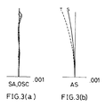
- FIGs. 3(a) and 3(b) show aberrations of a multiple focus lens of this invention toward the first disk of a first embodiment.
- FIGs. 4(a) and 4(b) show aberrations of a multiple focus lens of this invention toward the second disk of the first embodiment.
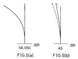
- FIGs. 5(a) and 5(b) show aberrations of a multiple focus lens of this invention toward the first disk of a second embodiment.
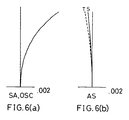
- FIGs. 6(a) and 6(b) show aberrations of a multiple focus lens of this invention toward the second disk of the second embodiment.
- FIGs. 7(a) and 7(b) show aberrations of a multiple focus lens of this invention toward the first disk of a third embodiment.
- FIGs. 8(a) and 8(b) show aberrations of a multiple focus lens of this invention toward the second disk of the third embodiment.
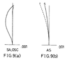
- FIGs. 9(a) and 9(b) show aberrations of a multiple focus lens of this invention toward the first disk of a fourth embodiment.
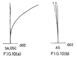
- FIGs. 10(a) and 10(b) show aberrations of a multiple focus lens of this invention toward the second disk of the fourth embodiment.
- FIGs. 11(a) and 11(b) show aberrations of a multiple focus lens of this invention toward the first disk of a fifth embodiment.
- FIGs. 12(a) and 12(b) show aberrations of a multiple focus lens of this invention toward the second disk of the fifth embodiment.
- FIGs. 13(a) and 13(b) show aberrations of a multiple focus lens of this invention toward the first disk of a sixth embodiment.
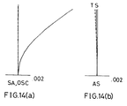
- FIGs. 14(a) and 14(b) show aberrations of a multiple focus lens of this invention toward the second disk of the sixth embodiment.
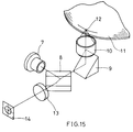
- FIG. 15 is a perspective view showing the configuration of one embodiment of an optical head apparatus and an optical information recording-reproducing apparatus according to this invention.
- FIG. 1 shows a lens construction with optical paths corresponding to the first through the fourth embodiments of the multiple focus lenses of this invention.
- incident light 1 enters an objective lens 2.
- the objective lens 2 is a bi-aspheric singlet.
- a phase grating 4 is formed on the incident-side surface 2a.
- the incident light 1 is focused on an information medium surface 3a of an disk 3.
- the disk 3 is 1.2mm thick, for example, +1st diffracted light of the phase grating 4 is used.
- 0th order diffracted light is used when the disk 3 is 0.6mm thick.
- FIG. 2 shows the lens construction with optical paths of the fifth embodiment of a multiple focus lens of this invention.
- incident light 1 transmits through a plane substrate 5 on which a phase grating is formed, and later enters a bi-aspheric objective lens 6 and is focused on an information medium surface of an disk 3.
- +1st order diffracted light and 0th order diffracted light of the phase grating on the plane substrate 5 are transmitted through the disk 3 with having 1.2mm thick and 0.6mm thick.
- the center wavelength for the lens design is 660nm
- the first disk thickness is 0.6mm
- refractive index of the disks is 1.57815
- numerical aperture (NA) toward the first disk is 0.60
- numerical aperture (NA) toward the second disk is 0.43.
- the symbols shown in Table 1 are commonly used.
- the phase grating is produced by using the super-high refractive index method (cf. "Describing holographic optical apparatuses as lenses” in 'Journal of Optical Society of America', Vol.67, No. 6, June 1977 by William C. Sweatt).
- the aspheric surface having a phase grating is indicated by Formula (6) similarly to a normal aspheric lens.
- the symbols are defined as indicated in Table 2. Parameter showing the performance of a lens are also defined in Table 3.
- DA L 1 (J 2 + D 2 ) - L 2 (J 1 + D 1 ) (J 1 + D 1 ) ⁇ (J 2 + D 2 )
- ZC
- Table 5 shows specific values for the first embodiment.
- a phase grating is formed on the incident side (the first surface) of a bi-aspheric objective lens.
- the 0th order diffracted light of the phase grating is used for the first disk while the +1st order diffracted light is used for the second disk.
- the parameters for the phase grating are shown in Table 6.
- Parameters of the lens performance are shown in Table 7.
- the residual coma ZC is as small as 3.35m ⁇ .
- the residual coma means the coma generated for the second disk after the lens is skew-adjusted for the first disk until the coma is completely corrected.
- FIG. 3(a) and 3(b) show the aberration toward the first disk of this embodiment, and FIGs. 4(a) and 4(b) show the aberration toward the second disk.
- dotted lines indicate spherical aberrations and solid lines indicate sine conditions.
- dotted lines indicate astigmatism in the tangential direction, and solid lines indicate astigmatism in the sagittal direction.
- Table 8 shows specific values of the second embodiment.
- a phase grating is formed on the incident side (the first surface) of a bi-aspheric objective lens.
- the 0th order diffracted light of the phase grating is used for the first disk while the +1st order diffracted light is used for the second disk.
- Parameters for the phase grating are shown in Table 9.
- Parameters for the lens performance are shown in Table 10.
- the residual coma ZC is as small as 2.82m ⁇ .
- the off-axis comas of the first and second disks are in balance. As a result, the off-axis performance of the objective lens does not deteriorate regardless of the disk thickness.
- FIGs. 6(a) and 6(b) show the aberration toward the first disk of this embodiment
- FIGs. 6(a) and 6(b) show the aberration toward the second disk.
- R 1 2.1558086
- n 1.58505
- CC 1 -0.5799059
- A1 4 0.1145763 ⁇ 10 -2
- A1 6 0.9992302 ⁇ 10 -4
- A1 8 0.4690929 ⁇ 10 -5
- A1 10 -0.5053259 ⁇ 10 -6
- A1 12 0.4115106 ⁇ 10 -8
- A1 14 0.3700554 ⁇ 10 -7
- A1 16 0.2946913 ⁇ 10 -8
- A1 18 -0.5026041 ⁇ 10 -8
- CC 2 0.6701698 ⁇ 10 +2
- A2 4
- Table 11 shows the specific values of the third embodiment.
- a phase grating is formed on the incident side (the first surface) of a bi-aspheric objective lens.
- the 0th order diffracted light of the phase grating is used for the first disk while the +1st order diffracted light is used for the second disk.
- Parameters for the phase grating are shown in Table 12.
- Parameters for the lens performance are shown in Table 13.
- the residual coma ZC is as small as 14.5m ⁇ .
- the difference between the focusing position of the first disk and that of the second disk is determined to be 0.47mm.
- this configuration is merely influenced by diffracted light other than the 0th and +1st order diffracted light, for example, stray light including +2nd order diffracted light or -1st order diffracted light.
- FIGs. 7(a) and 7(b) show the aberration toward the first disk of this embodiment, and FIGs. 8(a) and 8(b) show the aberration toward the second disk.
- Table 14 shows the specific values of the fourth embodiment.
- a phase grating is formed on the incident side (the first surface) of a bi-aspheric objective lens.
- the 0th order diffracted light of the phase grating is used for the first disk while the +1st order diffracted light is used for the second disk.
- Parameters for the phase grating are shown in Table 15.
- Parameters for the lens performance are shown in Table 16.
- the residual coma ZC is as small as 5.08m ⁇ .
- the diffracting optics are provided with positive power. Therefore, the chromatic aberration of the lens can be corrected by combining it with refractive elements.
- an erasable optical disk As for an erasable optical disk, light output of a semiconductor laser considerably varies at reproduction and at writing, and thus, the wavelength changes.
- the chromatic aberration toward the first disk which uses the diffracted light is determined to be zero near the employed wavelength.
- a lens without focal shift toward the wavelength variation of the semiconductor laser can be provided.
- FIGs. 9(a) and 9(b) show the aberration toward the first disk of this embodiment
- FIGs. 10(a) and 10(b) show the aberration toward the second disk.
- Table 17 shows the specific values according to this embodiment.
- a phase grating is formed on the second side of a plane substrate, not on the objective lens (cf. FIG. 2).
- the 0th order diffracted light of the phase grating is used for the first disk while the +1st order diffracted light is used for the second disk.
- Parameters for the phase grating are shown in Table 18.
- the thickness of the plane substrate and the refractive index are not described here, since the parallel incident light does not substantially influence the design.
- Parameters of the lens performance are shown in Table 19.
- the residual coma ZC is as small as 5.69m ⁇ .
- FIGs. 12(a) and 12(b) show the aberration toward the first disk of this embodiment
- FIGs. 12(a) and 12(b) show the aberration toward the second disk.
- R 1 2.235159
- n 1.58505
- WD 1 1.830
- WD 2 1.631
- CC 1 -0.5937478
- A1 4 0.5858212 ⁇ 10 -3
- A1 6 0.7802548 ⁇ 10 -4
- A1 8 0.3114840 ⁇ 10 -4
- A1 10 0.3927729 ⁇ 10 -5
- A1 12 0.5753915 ⁇ 10 -6
- A1 14 0.1415412 ⁇ 10 -6
- A1 16 0.3625273 ⁇ 10 -7
- A1 18 0.7264171 ⁇ 10 -8
- CC 2 -0.2269465 ⁇ 10 +2
- A2 4
- Table 20 shows the specific values of the sixth embodiment.
- a phase grating is formed on the incident side (the first surface) of a bi-aspheric objective lens.
- the 0th order diffracted light of the phase grating is used for the first disk while the +1st order diffracted light is used for the second disk.
- Parameters for the phase grating are shown in Table 21.
- Parameters of the lens performance are shown in Table 22. As shown in Table 22, the residual coma ZC is as small as 7.8m ⁇ .
- the diffracting optics are provided with positive power. Therefore, the chromatic aberration of the lens can be corrected by combining it with refractive elements.
- an erasable optical disk As for an erasable optical disk, light output of a semiconductor laser considerably varies at reproduction and at writing, and thus, the wavelength changes.
- the chromatic aberration toward the first disk which uses the diffracted light is determined to be zero near the employed wavelength.
- a lens without focal shift toward the wavelength variation of the semiconductor laser can be provided.
- the performance deterioration which occurs when the first and second surfaces of a lens decenter is controlled as much as possible. Such a lens is easily produced since the manufacturing tolerance is relaxed. FIGs.
- FIGs. 14(a) and 14(b) show the aberration toward the first disk of this embodiment
- FIGs. 14(a) and 14(b) show the aberration toward the second disk.
- R 1 2.42
- -72.94026 d 1.92
- n 1.68039
- WD 1 1.800
- WD 2 1.601
- CC 1 -0.5073552
- A1 4 0.6334136 ⁇ 10 -3
- A1 6 -0.7720862 ⁇ 10 -4
- A1 8 0.1135758 ⁇ 10 -4
- A1 10 0.9083080 ⁇ 10 -6
- A1 12 -0.4623212 ⁇ 10 -6
- A1 14 -0.1316056 ⁇ 10 -6
- A1 16 0.6379332 ⁇ 10 -8
- CC 2 -0.8242913 ⁇ 10 +4
- A2 4 0.1045507 ⁇ 10 -2
- A2 6 0.
- the objective lens explained in the above embodiments is preferably glass-molded or resin-molded.
- the diffraction grating on the plane substrate shown in the fifth embodiment is similarly glass-molded or resin-molded.
- FIG. 15 shows the configuration of an optical head apparatus using a multiple focusing objective lens of this invention, and an optical information recording-reproducing apparatus.
- a light beam radiated from a semiconductor laser 7 is reflected by a half mirror 8.
- the direction of the optical path is changed by a mirror 9, and focused on an information medium surface 12 of a disk 11 by an objective lens 10.
- the objective lens 10 has the structure shown in FIG. 1 or FIG. 2, and it focuses either 0th order diffracted light or +1st order diffracted light from the phase grating toward the disk 11.
- the focusing spot is diffracted by pits formed on the information medium surface 12.
- the laser light beam which is reflected and diffracted by the information medium surface 12 transmits through the half mirror 8, and focused on a photodetector 14 by an detecting lens 13. Data are read by detecting the variation of light quantity modulated on the information medium surface 12 by using electric signals from the photodetector 14.
- the objective lens 10 can have coma due to errors in processing. In such a case, the coma is corrected by tilting the optical axis of the objective lens 10 toward the optical axis of the disk 11. In the next step, the disk 11 is replaced by another disk different in thickness, so that either the 0th or the +1st order diffracted light which is not focused on the disk 11 is focused on the other disk.
- the objective lens 10 has the performance shown in the first to the fifth embodiments, so the coma substantially does not occur even if the substrate thickness varies. As a result, the skew adjustment need not be varied for every substrate thickness, and signals can always be recorded and reproduced with good spot focusing conditions.
- optical recording-reproducing apparatuses which can record and reproduce in a good condition are obtained by recording and reproducing the optical disk media varied in substrate thickness, by using the multiple focus objective lens or the optical head apparatus of this invention.
- light from a semiconductor laser is focused directly by one lens.
- the objective lens can be replaced by a finite magnification lens to disperse or converge light without it being made parallel by a collimating lens.
- the objective lenses for optical disks are not limited to bi-aspheric singlets. A lens which has one aspheric surface, a bi-spheric lens or a combination of such lenses can be used.
- the phase grating is formed on a plane substrate.
- the phase grating can also be formed on a spherical or aspherical surface.
- the hologram can be located at the incident side or at the radiating side.
- the order of the diffracted light is not limited to the 0th and the +1st order light, but -1st order diffracted light and +2nd order diffracted light are also available.
- diffracted light of at least three kind of orders can be used to reproduce data on at least three kinds of substrates of different thickness.
- a diffraction grating can be formed on either the front or the rear of an objective lens and be integrated with the lens.
Landscapes
- Physics & Mathematics (AREA)
- Optics & Photonics (AREA)
- General Physics & Mathematics (AREA)
- Optical Head (AREA)
- Lenses (AREA)
Applications Claiming Priority (3)
| Application Number | Priority Date | Filing Date | Title |
|---|---|---|---|
| JP21073595 | 1995-08-18 | ||
| JP210735/95 | 1995-08-18 | ||
| JP21073595 | 1995-08-18 |
Publications (2)
| Publication Number | Publication Date |
|---|---|
| EP0762155A1 true EP0762155A1 (de) | 1997-03-12 |
| EP0762155B1 EP0762155B1 (de) | 2003-01-22 |
Family
ID=16594248
Family Applications (1)
| Application Number | Title | Priority Date | Filing Date |
|---|---|---|---|
| EP96113202A Expired - Lifetime EP0762155B1 (de) | 1995-08-18 | 1996-08-16 | Eine Linse mit mehreren Brennweiten für einen optischen Kopf |
Country Status (4)
| Country | Link |
|---|---|
| US (1) | US5986779A (de) |
| EP (1) | EP0762155B1 (de) |
| KR (1) | KR100291198B1 (de) |
| DE (1) | DE69625862T2 (de) |
Cited By (4)
| Publication number | Priority date | Publication date | Assignee | Title |
|---|---|---|---|---|
| EP0820056A1 (de) * | 1996-07-18 | 1998-01-21 | Pioneer Electronic Corporation | Verfahren und Vorrichtung zur Korrektur von Komaaberrationen in einem optischen Kopf |
| US6304526B1 (en) | 1998-03-12 | 2001-10-16 | Matsushita Electric Industrial Co., Ltd. | Optical head |
| WO2002029797A1 (en) * | 2000-10-03 | 2002-04-11 | Koninklijke Philips Electronics N.V. | Optical scanning device |
| WO2004001732A1 (en) * | 2002-06-25 | 2003-12-31 | Koninklijke Philips Electronics N.V. | Optical scanning device including a tilt tolerant objective system |
Families Citing this family (29)
| Publication number | Priority date | Publication date | Assignee | Title |
|---|---|---|---|---|
| US6259668B1 (en) * | 1996-02-14 | 2001-07-10 | Samsung Electronics Co., Ltd. | Recording/reproducing apparatus having an optical pickup device to read from and record information to disks of different thicknesses |
| US6222812B1 (en) | 1996-08-29 | 2001-04-24 | Samsung Electronics Co., Ltd. | Optical pickup using an optical phase plate |
| US6639889B1 (en) | 1997-02-13 | 2003-10-28 | Samsung Electronics Co., Ltd. | Recording/reproducing apparatus including an optical pickup having an objective lens compatible with a plurality of optical disk formats |
| US6304540B1 (en) * | 1998-03-30 | 2001-10-16 | Samsung Electronics Co., Ltd. | Optical pickup compatible with a digital versatile disk and a recordable compact disk using a holographic ring lens |
| JP3408112B2 (ja) * | 1997-04-30 | 2003-05-19 | キヤノン株式会社 | 回折光学素子を有した光学部材及びそれを用いた光学系 |
| JP3362768B2 (ja) * | 1998-02-19 | 2003-01-07 | 株式会社ケンウッド | 光ピックアップ装置 |
| US6466371B1 (en) * | 2000-01-26 | 2002-10-15 | Aerial Imaging Corporation | Diffractive lens with gratings modified to offset effects caused by holding the lens at an angle with respect to a light source |
| KR100393188B1 (ko) * | 2000-12-29 | 2003-07-31 | 삼성전자주식회사 | 다초점 렌즈를 이용한 위상공액 홀로그래픽 정보 저장장치 및 정보 저장 방법 |
| KR100455477B1 (ko) * | 2000-12-29 | 2004-11-08 | 엘지전자 주식회사 | 광픽업 장치 |
| JP3712628B2 (ja) * | 2001-04-06 | 2005-11-02 | シャープ株式会社 | 対物レンズおよびその製造誤差の補正方法並びに該対物レンズを用いた光ピックアップ装置 |
| TW535001B (en) * | 2001-06-13 | 2003-06-01 | Pentax Corp | Objective lens for optical pick-up |
| CN100354660C (zh) * | 2002-04-18 | 2007-12-12 | 松下电器产业株式会社 | 光学元件、光学头、光学信息记录和再现装置、计算机、图像记录装置、图像再现装置、服务器和汽车导航系统 |
| KR20030093683A (ko) * | 2002-06-05 | 2003-12-11 | 삼성전자주식회사 | 호환형 광픽업 |
| US9453251B2 (en) * | 2002-10-08 | 2016-09-27 | Pfenex Inc. | Expression of mammalian proteins in Pseudomonas fluorescens |
| US7083304B2 (en) * | 2003-08-01 | 2006-08-01 | Illumination Management Solutions, Inc. | Apparatus and method of using light sources of differing wavelengths in an unitized beam |
| US20050030759A1 (en) * | 2003-08-04 | 2005-02-10 | Guide Corporation | Bifocal hyperbolic catadioptric collection system for an automotive lamp |
| US7246917B2 (en) * | 2003-08-12 | 2007-07-24 | Illumination Management Solutions, Inc. | Apparatus and method for using emitting diodes (LED) in a side-emitting device |
| US7433291B2 (en) * | 2003-10-03 | 2008-10-07 | Hoya Corporation | Objective lens |
| EP1673573A4 (de) * | 2003-10-06 | 2016-01-13 | Illumination Man Solutions Inc | Leuchtdioden verwendende verbesserte lichtquelle und verbessertes verfahren zum auffangen der von ihnen abstrahlenden energie |
| KR100555666B1 (ko) * | 2004-02-19 | 2006-03-03 | 삼성전자주식회사 | 홀로그래픽 worm에 대한 데이터 기록/재생장치 및 그방법 |
| EP1753996B1 (de) * | 2004-03-30 | 2011-06-29 | Illumination Management Solutions, Inc. | Vorrichtung und verfahren für verbesserte beleuchtungsflächenausfüllung |
| TWM267459U (en) * | 2004-11-19 | 2005-06-11 | Hon Hai Prec Ind Co Ltd | Camera lens |
| KR100741980B1 (ko) * | 2005-07-06 | 2007-07-23 | 엘지전자 주식회사 | 다초점 렌즈 |
| US7950821B1 (en) | 2007-10-26 | 2011-05-31 | Georgitsis Anthony C | Auxiliary lighting systems |
| JP2009252309A (ja) * | 2008-04-08 | 2009-10-29 | Hoya Corp | 光情報記録再生装置用対物レンズ、および光情報記録再生装置 |
| DE102008046569A1 (de) * | 2008-09-05 | 2010-03-11 | Blanco Gmbh + Co Kg | Aushärtbare Gießmasse zur Herstellung von Kunststoffformteilen |
| HRP20130712T1 (hr) * | 2009-02-20 | 2013-10-11 | Thales Canada Inc. | Optiäśki sustav za snimanje sa dvostrukim vidnim poljem i sa leä†om sa dvostrukim žarištem |
| TW201110489A (en) * | 2009-04-30 | 2011-03-16 | Corning Inc | Folded lasers system |
| CN114994928B (zh) * | 2022-05-12 | 2024-09-13 | 成都莱普科技股份有限公司 | 基于衍射光学元件的斜向多焦点产生系统及方法 |
Citations (4)
| Publication number | Priority date | Publication date | Assignee | Title |
|---|---|---|---|---|
| DE3421705C2 (de) * | 1984-06-12 | 1986-10-02 | Ingolf Dr. 3300 Braunschweig Weingärtner | Abtastobjektiv mit einem Hologramm |
| EP0468410A1 (de) * | 1990-07-27 | 1992-01-29 | Matsushita Electric Industrial Co., Ltd. | Optische Beugungslinse |
| EP0610055A2 (de) * | 1993-02-01 | 1994-08-10 | Matsushita Electric Industrial Co., Ltd. | Zusammengesetzte Objetivlinse mit zwei Brennpunkten, und Vorrichtung mit dieser Linse |
| US5349471A (en) * | 1993-02-16 | 1994-09-20 | The University Of Rochester | Hybrid refractive/diffractive achromatic lens for optical data storage systems |
Family Cites Families (2)
| Publication number | Priority date | Publication date | Assignee | Title |
|---|---|---|---|---|
| FR2642530A1 (fr) * | 1989-01-30 | 1990-08-03 | Seiko Epson Corp | Mecanisme de focalisation et tete optique |
| US5473471A (en) * | 1993-04-16 | 1995-12-05 | Matsushita Electric Industrial Co., Ltd. | Complex lens with diffraction grating |
-
1996
- 1996-08-12 US US08/695,397 patent/US5986779A/en not_active Expired - Lifetime
- 1996-08-16 DE DE69625862T patent/DE69625862T2/de not_active Expired - Lifetime
- 1996-08-16 EP EP96113202A patent/EP0762155B1/de not_active Expired - Lifetime
- 1996-08-17 KR KR1019960034026A patent/KR100291198B1/ko not_active Expired - Lifetime
Patent Citations (4)
| Publication number | Priority date | Publication date | Assignee | Title |
|---|---|---|---|---|
| DE3421705C2 (de) * | 1984-06-12 | 1986-10-02 | Ingolf Dr. 3300 Braunschweig Weingärtner | Abtastobjektiv mit einem Hologramm |
| EP0468410A1 (de) * | 1990-07-27 | 1992-01-29 | Matsushita Electric Industrial Co., Ltd. | Optische Beugungslinse |
| EP0610055A2 (de) * | 1993-02-01 | 1994-08-10 | Matsushita Electric Industrial Co., Ltd. | Zusammengesetzte Objetivlinse mit zwei Brennpunkten, und Vorrichtung mit dieser Linse |
| US5349471A (en) * | 1993-02-16 | 1994-09-20 | The University Of Rochester | Hybrid refractive/diffractive achromatic lens for optical data storage systems |
Cited By (5)
| Publication number | Priority date | Publication date | Assignee | Title |
|---|---|---|---|---|
| EP0820056A1 (de) * | 1996-07-18 | 1998-01-21 | Pioneer Electronic Corporation | Verfahren und Vorrichtung zur Korrektur von Komaaberrationen in einem optischen Kopf |
| US6304526B1 (en) | 1998-03-12 | 2001-10-16 | Matsushita Electric Industrial Co., Ltd. | Optical head |
| WO2002029797A1 (en) * | 2000-10-03 | 2002-04-11 | Koninklijke Philips Electronics N.V. | Optical scanning device |
| KR100809494B1 (ko) * | 2000-10-03 | 2008-03-04 | 코닌클리케 필립스 일렉트로닉스 엔.브이. | 광학주사장치 |
| WO2004001732A1 (en) * | 2002-06-25 | 2003-12-31 | Koninklijke Philips Electronics N.V. | Optical scanning device including a tilt tolerant objective system |
Also Published As
| Publication number | Publication date |
|---|---|
| KR970012387A (ko) | 1997-03-29 |
| US5986779A (en) | 1999-11-16 |
| EP0762155B1 (de) | 2003-01-22 |
| KR100291198B1 (ko) | 2001-09-17 |
| DE69625862D1 (de) | 2003-02-27 |
| DE69625862T2 (de) | 2003-06-18 |
Similar Documents
| Publication | Publication Date | Title |
|---|---|---|
| EP0762155B1 (de) | Eine Linse mit mehreren Brennweiten für einen optischen Kopf | |
| KR100560008B1 (ko) | 광 픽업 장치 | |
| US6927923B2 (en) | Objective lens, converging optical system, optical pickup apparatus and recording and/or reproducing apparatus | |
| JP3319686B2 (ja) | 光ピックアップ用2位置結像対物レンズ | |
| JPH09184975A (ja) | 対物レンズおよび光ヘッド | |
| US6324150B1 (en) | Optical pickup head using multiple laser sources | |
| HK1041090B (zh) | 可兼容不同厚度光记录介质的光拾取装置 | |
| KR101037031B1 (ko) | 광학 요소, 대물 광학 요소 및 광학 픽업 장치 | |
| JPH09180245A (ja) | 異なる厚さを有するディスクと互換が可能な記録再生用の光ピックアップ | |
| US20050025026A1 (en) | Objective lens, optical, pickup and optical information processing apparatus using the same | |
| KR100802845B1 (ko) | 광 픽업 장치용 대물 렌즈 및 광 픽업 장치 | |
| JP3235519B2 (ja) | 光ディスク用対物レンズ、光ヘッド装置及び光学情報記録再生装置 | |
| US7280444B2 (en) | Objective optical element, optical pickup device, and optical information recording and reproducing device | |
| US6992838B2 (en) | Objective lens with the diffractive surface for DVD/CD compatible optical pickup | |
| US7440382B2 (en) | Objective optical element with multiple diffractive surfaces and optical pickup device | |
| JP2005158089A (ja) | 光ディスク用の対物レンズとそれを用いた光ヘッド装置 | |
| US6900949B2 (en) | Optical system of optical pick-up | |
| JP3451152B2 (ja) | 光情報記録媒体の記録再生用光学系 | |
| JPH08334689A (ja) | 光ピックアップ用2位置結像対物レンズ | |
| JP2922851B2 (ja) | 多重焦点レンズ、光ヘッド装置及び光学情報記録再生装置 | |
| JP4280896B2 (ja) | 光ピックアップ装置用光学系、光ピックアップ装置、光情報記録再生装置及び色収差補正素子 | |
| US5015078A (en) | Aspherical single lens | |
| JPH1164724A (ja) | 光ディスク用対物レンズ及びそれを用いた光ヘッド装置 | |
| JPH09159808A (ja) | 二重焦点レンズおよびこれを用いた光ディスク記録再生装置 | |
| JPH0981953A (ja) | 光記録情報媒体の記録再生用光学系 |
Legal Events
| Date | Code | Title | Description |
|---|---|---|---|
| PUAI | Public reference made under article 153(3) epc to a published international application that has entered the european phase |
Free format text: ORIGINAL CODE: 0009012 |
|
| AK | Designated contracting states |
Kind code of ref document: A1 Designated state(s): DE FR GB |
|
| 17P | Request for examination filed |
Effective date: 19970116 |
|
| 17Q | First examination report despatched |
Effective date: 20010207 |
|
| GRAG | Despatch of communication of intention to grant |
Free format text: ORIGINAL CODE: EPIDOS AGRA |
|
| GRAG | Despatch of communication of intention to grant |
Free format text: ORIGINAL CODE: EPIDOS AGRA |
|
| GRAG | Despatch of communication of intention to grant |
Free format text: ORIGINAL CODE: EPIDOS AGRA |
|
| GRAH | Despatch of communication of intention to grant a patent |
Free format text: ORIGINAL CODE: EPIDOS IGRA |
|
| GRAH | Despatch of communication of intention to grant a patent |
Free format text: ORIGINAL CODE: EPIDOS IGRA |
|
| GRAA | (expected) grant |
Free format text: ORIGINAL CODE: 0009210 |
|
| AK | Designated contracting states |
Kind code of ref document: B1 Designated state(s): DE FR GB |
|
| REG | Reference to a national code |
Ref country code: GB Ref legal event code: FG4D |
|
| REF | Corresponds to: |
Ref document number: 69625862 Country of ref document: DE Date of ref document: 20030227 Kind code of ref document: P |
|
| ET | Fr: translation filed | ||
| PLBE | No opposition filed within time limit |
Free format text: ORIGINAL CODE: 0009261 |
|
| STAA | Information on the status of an ep patent application or granted ep patent |
Free format text: STATUS: NO OPPOSITION FILED WITHIN TIME LIMIT |
|
| 26N | No opposition filed |
Effective date: 20031023 |
|
| REG | Reference to a national code |
Ref country code: FR Ref legal event code: PLFP Year of fee payment: 20 |
|
| PGFP | Annual fee paid to national office [announced via postgrant information from national office to epo] |
Ref country code: DE Payment date: 20150811 Year of fee payment: 20 Ref country code: GB Payment date: 20150812 Year of fee payment: 20 |
|
| PGFP | Annual fee paid to national office [announced via postgrant information from national office to epo] |
Ref country code: FR Payment date: 20150629 Year of fee payment: 20 |
|
| REG | Reference to a national code |
Ref country code: DE Ref legal event code: R071 Ref document number: 69625862 Country of ref document: DE |
|
| REG | Reference to a national code |
Ref country code: GB Ref legal event code: PE20 Expiry date: 20160815 |
|
| PG25 | Lapsed in a contracting state [announced via postgrant information from national office to epo] |
Ref country code: GB Free format text: LAPSE BECAUSE OF EXPIRATION OF PROTECTION Effective date: 20160815 |