EP0762254A2 - Terrestrische Strahlsteuerungsterminals gebrauchende Referenz für Satellitenstrahlsteuerung - Google Patents
Terrestrische Strahlsteuerungsterminals gebrauchende Referenz für Satellitenstrahlsteuerung Download PDFInfo
- Publication number
- EP0762254A2 EP0762254A2 EP96306023A EP96306023A EP0762254A2 EP 0762254 A2 EP0762254 A2 EP 0762254A2 EP 96306023 A EP96306023 A EP 96306023A EP 96306023 A EP96306023 A EP 96306023A EP 0762254 A2 EP0762254 A2 EP 0762254A2
- Authority
- EP
- European Patent Office
- Prior art keywords
- satellite
- signal
- gain
- correction signal
- transmitting
- Prior art date
- Legal status (The legal status is an assumption and is not a legal conclusion. Google has not performed a legal analysis and makes no representation as to the accuracy of the status listed.)
- Ceased
Links
Images


Classifications
-
- H—ELECTRICITY
- H04—ELECTRIC COMMUNICATION TECHNIQUE
- H04B—TRANSMISSION
- H04B7/00—Radio transmission systems, i.e. using radiation field
- H04B7/14—Relay systems
- H04B7/15—Active relay systems
- H04B7/204—Multiple access
- H04B7/2041—Spot beam multiple access
-
- B—PERFORMING OPERATIONS; TRANSPORTING
- B64—AIRCRAFT; AVIATION; COSMONAUTICS
- B64G—COSMONAUTICS; VEHICLES OR EQUIPMENT THEREFOR
- B64G1/00—Cosmonautic vehicles
- B64G1/22—Parts of, or equipment specially adapted for fitting in or to, cosmonautic vehicles
- B64G1/24—Guiding or controlling apparatus, e.g. for attitude control
- B64G1/244—Spacecraft control systems
-
- B—PERFORMING OPERATIONS; TRANSPORTING
- B64—AIRCRAFT; AVIATION; COSMONAUTICS
- B64G—COSMONAUTICS; VEHICLES OR EQUIPMENT THEREFOR
- B64G1/00—Cosmonautic vehicles
- B64G1/10—Artificial satellites; Systems of such satellites; Interplanetary vehicles
- B64G1/1007—Communications satellites
-
- B—PERFORMING OPERATIONS; TRANSPORTING
- B64—AIRCRAFT; AVIATION; COSMONAUTICS
- B64G—COSMONAUTICS; VEHICLES OR EQUIPMENT THEREFOR
- B64G1/00—Cosmonautic vehicles
- B64G1/22—Parts of, or equipment specially adapted for fitting in or to, cosmonautic vehicles
- B64G1/24—Guiding or controlling apparatus, e.g. for attitude control
- B64G1/36—Guiding or controlling apparatus, e.g. for attitude control using sensors, e.g. sun-sensors, horizon sensors
- B64G1/363—Guiding or controlling apparatus, e.g. for attitude control using sensors, e.g. sun-sensors, horizon sensors using sun sensors
-
- B—PERFORMING OPERATIONS; TRANSPORTING
- B64—AIRCRAFT; AVIATION; COSMONAUTICS
- B64G—COSMONAUTICS; VEHICLES OR EQUIPMENT THEREFOR
- B64G1/00—Cosmonautic vehicles
- B64G1/22—Parts of, or equipment specially adapted for fitting in or to, cosmonautic vehicles
- B64G1/24—Guiding or controlling apparatus, e.g. for attitude control
- B64G1/36—Guiding or controlling apparatus, e.g. for attitude control using sensors, e.g. sun-sensors, horizon sensors
- B64G1/365—Guiding or controlling apparatus, e.g. for attitude control using sensors, e.g. sun-sensors, horizon sensors using horizon or Earth sensors
-
- B—PERFORMING OPERATIONS; TRANSPORTING
- B64—AIRCRAFT; AVIATION; COSMONAUTICS
- B64G—COSMONAUTICS; VEHICLES OR EQUIPMENT THEREFOR
- B64G1/00—Cosmonautic vehicles
- B64G1/22—Parts of, or equipment specially adapted for fitting in or to, cosmonautic vehicles
- B64G1/24—Guiding or controlling apparatus, e.g. for attitude control
- B64G1/36—Guiding or controlling apparatus, e.g. for attitude control using sensors, e.g. sun-sensors, horizon sensors
- B64G1/366—Guiding or controlling apparatus, e.g. for attitude control using sensors, e.g. sun-sensors, horizon sensors using magnetometers
-
- B—PERFORMING OPERATIONS; TRANSPORTING
- B64—AIRCRAFT; AVIATION; COSMONAUTICS
- B64G—COSMONAUTICS; VEHICLES OR EQUIPMENT THEREFOR
- B64G1/00—Cosmonautic vehicles
- B64G1/22—Parts of, or equipment specially adapted for fitting in or to, cosmonautic vehicles
- B64G1/66—Arrangements or adaptations of apparatus or instruments, not otherwise provided for
-
- B—PERFORMING OPERATIONS; TRANSPORTING
- B64—AIRCRAFT; AVIATION; COSMONAUTICS
- B64G—COSMONAUTICS; VEHICLES OR EQUIPMENT THEREFOR
- B64G3/00—Observing or tracking cosmonautic vehicles
-
- H—ELECTRICITY
- H04—ELECTRIC COMMUNICATION TECHNIQUE
- H04B—TRANSMISSION
- H04B7/00—Radio transmission systems, i.e. using radiation field
- H04B7/14—Relay systems
- H04B7/15—Active relay systems
- H04B7/185—Space-based or airborne stations; Stations for satellite systems
- H04B7/1851—Systems using a satellite or space-based relay
- H04B7/18517—Transmission equipment in earth stations
Definitions
- This invention relates in general to satellite systems and, in particular, to a mobile communications satellite system using low earth orbit (LEO) satellites.
- LEO low earth orbit
- LEO satellites suitable for use in a mobile communications satellite system have Radio Frequency (RF) communications coverage areas, corresponding to antenna patterns (footprints), which sweep across the earth in the direction of the satellite's orbital path.
- RF Radio Frequency
- antenna patterns footprints
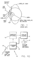
- Fig. 1 shows these three directions as a roll axis direction, a pitch axis direction, and a yaw axis direction.
- the roll axis is pointed in the direction of the satellite velocity vector and is in the plane of the orbit.
- the pitch axis is perpendicular to the roll axis and to the orbit plane.
- the yaw axis is perpendicular to each of the roll and pitch axes and is in the plane of the orbit.
- a satellite is nominally pointed with its yaw axis directed toward the center of the earth.
- the coverage area of the communications beam if the antenna is fixed to the body of the satellite, or the antenna gimble point if the antenna is steered, can be directed either in the direction of the satellite's velocity vector (or away from the velocity vector) by pitching the satellite. This is accomplished by rotating the satellite about its pitch axis.
- the beam can be steered perpendicular to the velocity vector by rolling the satellite, i.e., by rotating the satellite about the roll axis.
- the satellite beam may be steered in rotation by rotating the satellite about its yaw axis.
- commands are issued to the satellite's attitude control system to perform these rotations.
- the attitude control system is used to maintain the satellite pointed in a particular direction by controlling the satellite's attitude with respect to the various axes and thus point the antenna pattern beam or beam(s) in a desired direction relative to the surface of the earth (or a desired direction in space).
- LEO satellites move in space and time with the antenna beam on the ground sweeping along with the satellite, alternatively covering and uncovering areas on the ground.
- LEO satellites may have the antenna roll, pitch and yaw axes fixed, and thus move a beam pattern over the surface of the earth.
- a sub-satellite point is a point on the surface of the earth at which the yaw axis is pointed, and is located along a vector from the earth's center to the point on the orbit where the satellite is located.
- the SSP is defined to be at the intersection of this line and the earth's surface.
- the antenna beam from a LEO satellite can be analogized as a push broom, where the yaw axis is the broom's handle and where the satellite's coverage area, that is, a region illuminated by the beam, is pushed over the earth's surface.
- the portion of the earth's surface that can be seen from the orbiting LEO satellite at any instant is its coverage footprint.
- the antenna beam may be all or some portion of the footprint.
- the coverage area has a size and shape which typically depends on the altitude of the orbit and the elevation angle to the satellite from the extremity of the coverage area footprint.
- the antenna beam does not necessarily need to be regular in shape, nor does it have to illuminate all of the coverage area.
- the coverage area is a circular area centered on the SSP.
- the satellite beam is typically divided into smaller sub-beams for communications efficiency. It is this set of sub-beams that usually require a preferential direction to be specified.
- the antenna is fixed to the body of the satellite. However, this is not necessary, and the antenna can instead be gimbled and directed to point in some direction with respect to the satellite axes. In this case instrumentation on the gimble axes (either single or two axes) provides offset information to the satellite or ground control for the determination of the attitude of the satellite.
- the satellite system requires reference information in order to maintain a preferential satellite direction with respect to the yaw axis (and other axes) for the antenna beam as it moves over the earth.
- the attitude control system on-board the satellite performs this function. It can use any of a number of conventional control methods to orient the satellite in the preferred direction.
- reference information is required to determine the satellite's attitude and to therefore determine and send commands to the attitude control system so as to change the pointing direction of the satellite or antenna that is creating the coverage area on the ground.
- This reference information has conventionally been obtained by earth sensors, sun sensors, magnetometers, and other external reference devices.
- This invention seeks to provide satellite attitude control reference information from either users of the system or from fixed reference transmitters having known locations on the earth's surface.
- the invention seeks to enable the provision of a satellite attitude control system that compares the gains of signals received from one or more reference transmitters, positioned at known locations on the earth's surface, with expected gains as indicated by a stored map of satellite antenna gain contours, and that then determines an attitude correction from a difference in the received and expected gains.
- a satellite communication system has at least one satellite with an antenna that generates a moving beam pattern on the surface of the earth.
- the beam pattern is comprised of a plurality of sub-beams.
- a method of determining an attitude correction signal for the satellite by the steps of: (a) providing at least one reference transmitter at a known location on the surface of the earth; (b) transmitting at least one signal from the at least reference transmitter into at least one of the subbeams; (c) receiving the at least one signal with the satellite antenna and transponding the received at least one signal to a ground station.
- a next step of the method receives the transponded at least one signal with the ground station; (e) determines a gain of the received at least one signal; (f) compares the determined gain to a gain expected to be received based on a predetermined knowledge of a spatial variation in gain of the satellite antenna; and (g) and determines a difference between the determined gain and the expected gain to derive a correction signal indicative of an attitude error of the satellite.
- the method may comprise the steps of transmitting the correction signal to the satellite; and correcting the attitude of the satellite in accordance with the correction signal.
- the step of transmitting at least one signal from the at least reference transmitter can include a step of transmitting a plurality of signals from one reference transmitter, a step of transmitting a plurality of signals from a plurality of reference transmitters, or a step of transmitting one signal from individual ones of a plurality of reference transmitters.
- the satellite has a preferred direction of travel and a preferred orientation in space at any given point in time.
- teaching of this invention is illustrated primarily in the context of yaw axis control, it should be realized that the teaching of this invention applies to all axes of orientation.
- the satellite has a preferred yaw angle with respect to the direction of travel over the surface of the earth, and a yaw error angle exists such that the satellite's actual direction differs from the preferred direction.
- the step of determining determines an apparent direction of travel that differs from the actual direction of travel by an angle related to a knowledge uncertainty as to the satellite attitude.
- the method further includes the steps of transmitting the correction signal to the satellite and correcting the attitude of the satellite in accordance with the correction signal by rotating the satellite about the yaw axis so as to reduce a magnitude of the yaw error angle.
- the signals are transmitted, transponded and received as spread spectrum, code division multiple access signals.
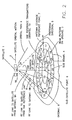
- a satellite 1 is in motion along the satellite velocity vector 2 along an orbital path x and thus moves a coverage area 3 forming a beam pattern along the ground.
- the coverage area 3 corresponds to a satellite beam that is typically divided, by example, into some number of concentrically arranged sub-beams 4, such as 20 sub-beams.
- the sub-beams are generally required to point in a preferential or preferred direction 5 with respect to the yaw axis.
- the preferred direction 5 may vary with time and may rotate at some specified rate.
- the satellite 1 is assumed to be controlled around the yaw axis, which is defined as a line between the center of the earth and the satellite.
- the intersection of this line with the earth's surface is referred to herein as the satellite's sub-satellite point (SSP) 6.
- SSP sub-satellite point
- the preferred direction 5 is a vector extending from the SSP 6 to a point 7 on the outer edge of the satellite antenna coverage region 3, or to any other convenient point. It is not necessary for the beam to be centered on the SSP 6, and can instead be at an arbitrary angle to the SSP 6 and can cover less than the entire coverage area footprint area of the satellite.
- At least one terrestrial gateway (GW) 8 is bidirectionally coupled to the satellite 1 through an RF link or feeder link 9 comprised of an RF uplink 9A, to a satellite feeder link receive antenna lA, and an RF downlink 9B, from a satellite transmit antenna lB.
- Each SBSRT 10 includes an antenna 10a, such as an omni-directional antenna, and is capable of transmitting a signal to the satellite 1, and may also be capable of receiving a signal from the satellite 1.
- the SBSRTs 10 communication via second RF links (not feeder links) with the satellite 1.
- the satellites there are a total of 48 satellites in, by example, a 1414 km Low Earth Orbit (LEO).
- LEO Low Earth Orbit
- the satellites are distributed in eight orbital planes with six equally-spaced satellites per plane (Walker constellation).
- the orbital planes are inclined at 52 degrees with respect to the equator and each satellite completes an orbit once every 114 minutes.
- This approach provides approximately full-earth coverage with, preferably, at least two satellites in view at any given time from a particular user location between about 70 degree south latitude and about 70 degree north latitude.
- a user is enabled to communicate to or from nearly any point on the earth's surface within a gateway 8 coverage area to or from other points on the earth's surface via one or more GWs 8 (by way of a public switched telephone network (PSTN) connection to the GW 8) and one or more of the satellites 1.
- PSTN public switched telephone network
- SS spread spectrum
- CDMA code division multiple access
- TDMA Time Division Multiple Access
- FDMA Frequency Division Multiple Access
- the low earth orbits of the satellites 1 permit low-powered fixed or mobile user terminals to communicate via the satellites 1, each of which functions, in a presently preferred embodiment of this invention, solely as a "bent pipe” repeater to receive a communications traffic signal (such as speech and/or data) from a user terminal or from a gateway 8, to convert the received communications traffic signal to another frequency band, and to then re-transmit the converted signal.
- a communications traffic signal such as speech and/or data
- a gateway 8 to convert the received communications traffic signal to another frequency band
- the user terminals communicate via, by example, L-band RF links (uplink or return link) and Sband RF links (downlink or forward link) through return and forward satellite transponders (shown in Fig. 6), respectively.
- the return L-band RF links may operate within a frequency range of 1.61 GHz to 1.625 GHz, with a bandwidth of 16.5 MHz, and are modulated with, in accordance with the preferred spread spectrum technique, multiple 1.25 MHz segments.
- the forward S-band RF links may operate within a frequency range of 2.485 GHz to 2.5 GHz, a bandwidth of 16.5 MHz, and are also modulated in accordance with the spread spectrum technique in multiple 1.25 MHz segments.
- the 16.5 MHz bandwidth of the forward link is partitioned into 13 channels with, by example, up to 128 users being assigned per channel.
- the return link may have various bandwidths, and a given user terminal may or may not be assigned a different channel than the channel assigned on the forward link.
- the gateway 8 communicates with the satellites 1 via, by example, a full duplex RF link 9 (forward link 9a (to the satellite), return link 9b (from the satellite)) that operates within a range of frequencies generally above 3 GHz and preferably in the C-band.
- the C-band RF links bidirectionally convey the communication feeder links, and also convey satellite commands to the satellites and telemetry information from the satellites.
- the forward feeder link 9a may operate in the band of 5 GHZ to 5.25 GHz
- the return feeder link 9b may operate in the band of 6.875 GHz to 7.075 GHz.
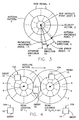
- Fig. 3 for illustrating an exemplary antenna pattern 3 of sub-beams 4 centered on the SSP 6.
- the satellite antenna pattern 3 is moving as the satellite 1 moves along the velocity vector 2, alternatively covering and uncovering points on the ground.
- the pattern has the preferred direction 5 with respect to the velocity vector 2, and at any time may be fixed or rotating at some rate.
- the accuracy of beam pointing has two components.
- a first component is the error angle 11, which in this embodiment of the invention is a yaw error.
- the yaw error is the difference between the preferred direction 5 and the actual direction 12 that the beam is moving.
- the second component is a knowledge uncertainty angle 13, that is, the uncertainty in knowledge of the actual direction.
- the knowledge uncertainty gives rise to an "apparent" direction 14 of satellite beam pattern motion over the surface of the earth. If no yaw axis control is performed, the yaw error angle 11 will change with time. Considering various effects and perturbations due to orbital dynamics, thermal effects, drag, mechanical forces and other factors, the yaw error angle 11 may oscillate, may remain constant with offset, or may rotate in either direction about the SSP 6.
- a satellite attitude controller lC (Fig. 10) is used to manoeuvre the satellite 1 in order to point the antenna, by example, in the preferred direction 5, thus minimizing the beam positioning error 11 (for the example case, the yaw error), using values and information that are obtained in accordance with the teaching of this invention.
- one or a plurality of the SBSRTs 10 are distributed over the ground surface area at known locations.
- the satellite beam pattern 3 of the LEO satellite 1 moves across the pattern of SBSRTs 10.
- the antenna beam 3 and associated SSP 6 sweep across the earth's surface, illuminating the SBSRTs 10 in turn and causing them to appear to move from sub-beam to sub-beam.
- a SBSRT 10 that transmits an uplink signal will be received by the satellite 1 with a composite pattern of all sub-beams 4.
- the sub-beams 4 have individual spatial variations in gain, referred to herein as the antenna gain contours Gl and G2 for sub-beams N and M, respectively.
- the SBSRT 10 is covered by a portion of the beam from the moving satellite 1.
- the apparent antenna gain of sub-beams N and M changes with time. That is, the magnitudes of Gl and G2 can be considered to vary with time.
- the signal from the SBSRT 10 is received at the satellite 1 from the sub-beams N and M, and is repeated by the satellite 1 to the gateway 8 over the return feeder link 9B (Fig. 2).
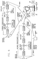
- the operation of the RF links and the repeaters is shown.
- the forward feeder link 9A e.g, a C-band link
- reception is made by the satellite feeder link antenna 20 and a translation in frequency is made in a forward repeater or transponder 22.
- the frequency translated forward signal is transmitted by the satellite antenna 24 as a forward service link 26 (e.g., S-band) for reception by the SBSRT 10.
- a return service link 28 (e.g, L-band) is transmitted by the SBSRT 10 to a receive antenna 30 of the satellite 1, and a translation in frequency is made in a return repeater or transponder 34.
- the frequency translated return signal is transmitted by the satellite antenna 32 as the return feeder link 9B for reception by the GW 8.
- the principle of operation is based on receiving a signal or signals from one or more of the SBSRTs 10 at the GW 8, determining where in the satellite's antenna pattern the SBSRT 10 is located, and relating the determined location to a database 35 of stored antenna gain contour values.
- the GW 8, or a Satellite Operations Control Center (SOCC) 40 or a Ground Operations Control Center (GOCC) 44 (Fig. 9) can store a gain contour map for each satellite of the constellation, or a generalized map that relates to all of the satellites.
- the map can be periodically updated to reflect changes in the satellite's status, such as changes in the operability of on-board linear amplifiers that generate the various sub-beams.
- the map or maps can be determined by calculation, based on the geometry of the phased array satellite antennas, and/or may be generated empirically by measuring the gain contour values either by testing on the ground or by performing in-orbit testing.
- Fig. 11 is an exemplary gain contour map for a single inner sub-beam.
- the signals from a single one of the SBSRTs 10 are received by the GW 8 either singularly (e.g., from a single sub-beam 4), or as a plurality of copies from a plurality of the sub-beams 4.
- a mapping of fixed SBSRT 10 locations on the earth's surface into expected fixed positions in the antenna beam map results in a calculation of the angular offset between the preferred direction 5 and the apparent direction 14. That is, a determination of the yaw error angle 11 is made from the signal received from the SBSRT 10 .
- the GW 8 based on the stored patterns of antenna gain values as a function of sub-beam gain contours, the GW 8 expects to find that the signal 28 transmitted by the SBSRT 10 into, by example, sub-beams N and M experiences satellite antenna gains of gl' and g2', it being remembered that the location of the satellite 1 is known by the GW 8 from satellite ephemerides data, while the location of the SBSRT 10 is known a priori.
- the gains can be determined from received signal strength or power measurements made by the GW 8. However, in actuality the GW8 determines that the antenna gains are G1 and G2 in the sub-beams N and M, respectively.
- the difference in gain(s) between the expected and the measured indicates a difference between the expected and actual beam orientation with respect to the fixed SBSRT 10. This difference is then employed to derive a yaw correction that is used by the satellite attitude controller lC (Fig. 10) to rotate the satellite 1 about the yaw axis (in this example) so as to drive the angular beam error towards zero.
- the teaching of this invention can also employ signals received from user terminals, either mobile, handheld or fixed. That is, when establishing a connection with a user terminal, in particular mobile and handheld terminals, the GW 8 preferably performs a position location on the user terminal using GPS positioning techniques or other suitable positioning techniques. The location of a fixed user terminal, such as one having an antenna located on top of an office building or a mast, can be initially determined with great precision when the antenna is first installed. Also, whether using the SBSRTs 10 or user terminals, the GW 8 may also actively power control the terminal transmitter so as to substantially equalize the received power from each terminal. As such, the power at which a given transmitter is transmitting is also known to the GW 8.
- the beam steering reference technique of this invention need not be continuously active. That is, during periods of high communications loading, and for a CDMA implementation, it may not be desirable to assign a spreading code (e.g., a Walsh code) to one of the SBSRTs 10, thereby freeing the code(s) for use by a user terminal.
- a spreading code e.g., a Walsh code
- the GW 18 can selectively activate one or more of the SBSRTs 10 over the forward link, assign one or Walsh codes to the SBSRTs 10, and then perform the determination of satellite attitude error (e.g., yaw error) based on transmissions from the activated one or ones of the SBSRTs 10.
- the teaching of this invention can operate in one of a number of modes or methods.
- one method employs multiple, single SBSRT 10 transmission (i.e. transmissions from several SBSRTs 10 simultaneously).
- Another method employs multiple SBSRT link copies, from a single SBSRT 10.
- a further method employs multiple copies of SBSRT link copies from multiple SBSRTs 10.
- Method 1 utilizes multiple SBSRTs 10 each transmitting a single return service link 28 to the GW 8 through one of the subbeams 4. That is, a plurality of the SBSRTs 10, which are located in different sub-beams (SB) A, B, C etc., each transmit a signal to the satellite 1.
- the signals may be simultaneously transmitted or not. If not transmitted simultaneously, then preferably the SBSRTs 10 time tag their respective transmissions by encoding the system time into the transmission.
- the signals are repeated in the satellite return link transponder 30 (Fig. 6) and received at the GW 8.
- the received signal level, the time differences between the signals, and other link values are developed by the gateway 8 and stored in a database 8a.
- the received signal gain values are developed and the apparent satellite direction 14 is determined.
- the preferred direction 5 is known a priori by the GW 8 and is also stored in the database 8a.
- the actual direction 12 is not able to be known exactly, and differs from the apparent direction 14 by the angular difference referred to previously as the knowledge uncertainty 13. Therefore, the angular difference, by example the yaw error angle 11, is calculated and stored for future use, or may be transmitted directly to the satellite attitude controller 1C (Fig. 10) for correction implementation. In either case, after correction any residual error (as considered by this invention) is the knowledge uncertainty 13.
- the SBSRTs 10 are shown transmitting signals from one or more sub-beams (e.g. SB-A and SB-B) on return service links 28a and 28b, respectively, which are then repeated on feeder link 9b.
- These signals can, by example, be transmitted by a repeater configured as shown in Figure 7B, which is but one example of a suitable satellite repeater.
- a satellite phased array service link receiver antenna 1d receives the links 28a and 28b which are applied to SB-A and SB-B low noise amplifiers (LNAs), are then down converted, are multiplexed together, and appear as signals in the various feeder link channels (by example A and B of Fig. 7C) which correspond to the sub-beams A and B.
- LNAs low noise amplifiers
- a first, most accurate, technique uses at least one of the SBSRTs 10, or some other transmitter having a known location on the surface of the earth, measures the gain of each transmitter as received at the GW 8, and compares the measured gain with expected values known by the GW 8 or by other ground station.
- a second technique uses only the knowledge of which feeder link channel(s) the SBSRT(s) 10 are located in.
- a third technique employs the transmission of an aggregate of communication's users, instead of an SBSRT 10, which are located in one or some of the sub-beams 4. In this latter case, by example, users which are expected to be in subbeams A and B are found instead in, by example, sub-beams C and D. If this is found to be the case the GW 8 or other ground station is enabled to estimate the apparent direction 14 may be determined without the use of SBSRT devices.
- the Method 2 referred to above i.e., single SBSRT 10, multiple link transmission, uses a single SBSRT 10 which is transmitting one signal, but which produces multiple links. That is, the signals are automatically received in both the sub-beam A and B channels.
- SS-CDMA Spread Spectrum, Code Division Multiple Access
- a service link signal from a single SBSRT 10 is transmitted on multiple (e.g., two) return service links 28' and 28'' using an omni-directional antenna 10A.
- the multiple links 28' and 28'' are each received by the satellite 1, see also Fig. 7B, and resolved into input to sub-beams A and B.
- Method 3 uses multiple SBSRTs 10 that each operate as in Method 2. That is, a plurality of SBSRTs 10 each transmit multiple links 28' and 28''. For this case the multiple links are received by multiple sub-beams and the additional information as to the gains of the various links is used to develop a precise value for the apparent direction 14.
- the first two methods are considered together.
- the satellite 1 is steered with the resultant error value(s) 11 from the GW 8, which determines the error value 11, transmits the information to the satellite 1 in real time (Method A), or non-real time (Method B), for further usage by the satellite attitude control system lC shown in Fig. 10.
- the attitude control system lC includes a command link receive antenna, which may be the uplink feeder link receive antenna 20 shown in Fig. 6, a command receiver lD, and attitude controller lE, and a suitable attitude control mechanism 1F (e.g., momentum wheels, magnetic torques, gyros or thrusters).
- An optional on-board computer lG can be included for calculating the required attitude adjustment(s) from the received information, and/or for storing the received command steering information for later use. If the computer lG is not provided, then the command link conveys the required attitude control operations which are acted on by the attitude controller lE.
- the attitude controller lE and attitude control mechanism lf cooperate to rotate the satellite 1 about the yaw axis (see Fig. 2) so as to reduce the yaw error angle (ideally) to zero.
- the satellite 1 For a LEO system the satellite 1 is moving over a substantial number of GWs 8. Some or all of these GWs 8 may have the command capability to command the satellite 1 and issue steering instructions to the satellite. Further, the satellite 1 (Method B) may have the computer 1G as a part of its command and control system which can accept the reference information and either store it for later use, update a steering algorithm, or otherwise utilize the reference information.
- the GW 8 transmits the error signal(s) 11 or altitude control information derived from the error data to the satellite 1.
- the command link information is received by the command receiver lD over the command link.
- the signal after reception, down conversion, decoding and processing is delivered either to the on-board computer 1G (Method B) or directly to the attitude control system lE (Method A).
- the data may be used to update a stored program for controlling the satellite 1 either in real time (Method A), or at some later time (Method B).
- the signal can be delivered directly to the attitude controller and the pointing error corrected. Further updates or corrections are made as the satellite 1 progresses over the surface of the earth and passes over other GWs 8 and SBSRTS 10.
- attitude controller lE issues instructions to one or more types of attitude control mechanisms lF to change the attitude of the satellite 1 to reduce the error angle 11.
- the satellite 1 relays the SBSRT 10 (or user terminal) transmissions to the gateway 8 over the return feeder link 9B as the satellite 1 moves across the GW 8.
- the signals are received by GW 8, and the error angle 11 is determined at the GW 8 as described previously.
- the error angle 11 result is communicated to a Satellite Operations Control Center (SOCC) 40 via a terrestrial or ground data network (GDN) 42.
- SOCC Satellite Operations Control Center
- GDN terrestrial or ground data network
- the resultant error angle 11 and/or other data based on the error angle is received by the SOCC 40 from the GDN 42, and is then communicated (in real time or non-real time) to the satellite 1 over the command link from the SOCC 40.
- the error signal is received by the command receiver lD (Fig. 10), is downconverted, decoded and otherwise processed and formatted.
- the signal is then sent to the altitude controller lE directly or indirectly via the optional on-board computer lG for processing.
- the resultant information is applied to the attitude control mechanism lF.
- the real time steering of Method C can be affected, or the non-real time steering of Method D can be used.
- the attitude correction technique has been described above primarily in the context of a cooperative effort between the SBSRT(s), the satellite, and at least one ground station, it should be appreciated that all or some part of the ground station functionality can be incorporated within the satellite.
- the satellite can store its own antenna gain contour map(s), can determine the gain of the signal received from the SBSRT or user terminal, can calculate its attitude error (e.g., yaw error), and can then take corrective action.
Landscapes
- Engineering & Computer Science (AREA)
- Remote Sensing (AREA)
- Aviation & Aerospace Engineering (AREA)
- Radar, Positioning & Navigation (AREA)
- Combustion & Propulsion (AREA)
- Chemical & Material Sciences (AREA)
- Astronomy & Astrophysics (AREA)
- General Physics & Mathematics (AREA)
- Physics & Mathematics (AREA)
- Signal Processing (AREA)
- Computer Networks & Wireless Communication (AREA)
- Automation & Control Theory (AREA)
- Life Sciences & Earth Sciences (AREA)
- Environmental & Geological Engineering (AREA)
- General Life Sciences & Earth Sciences (AREA)
- Geochemistry & Mineralogy (AREA)
- Geology (AREA)
- Radio Relay Systems (AREA)
- Variable-Direction Aerials And Aerial Arrays (AREA)
Applications Claiming Priority (2)
| Application Number | Priority Date | Filing Date | Title |
|---|---|---|---|
| US518524 | 1995-08-23 | ||
| US08/518,524 US5758260A (en) | 1995-08-23 | 1995-08-23 | Satellite beam steering reference using terrestrial beam steering terminals |
Publications (2)
| Publication Number | Publication Date |
|---|---|
| EP0762254A2 true EP0762254A2 (de) | 1997-03-12 |
| EP0762254A3 EP0762254A3 (de) | 1997-05-28 |
Family
ID=24064302
Family Applications (1)
| Application Number | Title | Priority Date | Filing Date |
|---|---|---|---|
| EP96306023A Ceased EP0762254A3 (de) | 1995-08-23 | 1996-08-19 | Terrestrische Strahlsteuerungsterminals gebrauchende Referenz für Satellitenstrahlsteuerung |
Country Status (9)
| Country | Link |
|---|---|
| US (2) | US5758260A (de) |
| EP (1) | EP0762254A3 (de) |
| JP (1) | JPH09136699A (de) |
| KR (1) | KR970011902A (de) |
| AU (1) | AU6392396A (de) |
| BR (1) | BR9610121A (de) |
| CA (1) | CA2180058A1 (de) |
| TW (1) | TW307072B (de) |
| WO (1) | WO1997008851A1 (de) |
Cited By (6)
| Publication number | Priority date | Publication date | Assignee | Title |
|---|---|---|---|---|
| WO2001002922A1 (en) * | 1999-07-07 | 2001-01-11 | Honeywell Inc. | Agile satellite targeting |
| EP0841760A3 (de) * | 1996-11-08 | 2001-02-21 | Lucent Technologies Inc. | Zellgruppierungsverfahren und Antennendiagram dazu für drahtloses Kommunikationsnetz mit Antennenträger auf Satelliten |
| EP1162765A3 (de) * | 2000-06-05 | 2003-12-10 | Trw Inc. | Vorrichtung und Verfahren zur Verringerung der Verzögerung und der Pufferung in Vielfachzugriffkommunikationssystemen |
| WO2011138563A1 (fr) * | 2010-05-07 | 2011-11-10 | Centre National D'etudes Spatiales | Systeme hybride terrestre - satellitaire de radiocommunication cellulaire capacite elevee |
| CN103026640B (zh) * | 2010-05-07 | 2016-11-30 | 国家宇宙研究中心 | 混合蜂窝无线电通信系统和用于保持一致性的处理方法 |
| WO2017064676A1 (en) * | 2015-10-14 | 2017-04-20 | Worldvu Satellites Limited | Method for maintaining signal-to-noise ratio at a user terminal in a satellite system |
Families Citing this family (63)
| Publication number | Priority date | Publication date | Assignee | Title |
|---|---|---|---|---|
| US6072768A (en) * | 1996-09-04 | 2000-06-06 | Globalstar L.P. | Automatic satellite/terrestrial mobile terminal roaming system and method |
| GB2320232B (en) * | 1996-12-12 | 2000-09-27 | Ico Services Ltd | Satellite and Method of Operating a Satellite |
| JPH10256974A (ja) * | 1997-03-14 | 1998-09-25 | Mitsubishi Electric Corp | 移動体衛星通信システム |
| US5790071A (en) * | 1997-07-03 | 1998-08-04 | Lockheed Martin Corp. | Method for determining orientation and attitude of a satellite- or aircraft-borne phased-array antenna |
| US6781968B1 (en) * | 1997-09-08 | 2004-08-24 | Marc Arnold | Wireless communication system, apparatus and method using an atmospheric platform having a wideband trunkline |
| US6101385A (en) * | 1997-10-09 | 2000-08-08 | Globalstar L.P. | Satellite communication service with non-congruent sub-beam coverage |
| US6144334A (en) * | 1998-02-26 | 2000-11-07 | Analytical Graphics, Inc. | Method and apparatus for calculating access between satellite constellations and ground targets |
| US6148176A (en) * | 1998-03-11 | 2000-11-14 | Ericsson Inc. | Methods and systems for acquiring service within a satellite communications system |
| US6396819B1 (en) | 1998-03-21 | 2002-05-28 | Richard D. Fleeter | Low-cost satellite communication system |
| US6208858B1 (en) * | 1998-07-21 | 2001-03-27 | Qualcomm Incorporated | System and method for reducing call dropping rates in a multi-beam communication system |
| US6317029B1 (en) * | 1998-08-07 | 2001-11-13 | Aeroastro, Llc | In situ remote sensing |
| US6150977A (en) * | 1998-10-30 | 2000-11-21 | Trw Inc. | Method for enhancing the performance of a satellite communications system using multibeam antennas |
| US6321065B1 (en) * | 1998-10-30 | 2001-11-20 | Trw Inc. | Performance enhancement of open-loop power control for satellite communication systems |
| US6157817A (en) * | 1999-02-04 | 2000-12-05 | Hughes Electronics Corporation | Method for in-orbit multiple receive antenna pattern testing |
| US6184825B1 (en) * | 1999-06-29 | 2001-02-06 | Trw Inc. | Method and apparatus for radio frequency beam pointing |
| US6400927B1 (en) * | 1999-08-30 | 2002-06-04 | Motorola, Inc. | Method and apparatus for a mapping receiver |
| US6704543B1 (en) * | 1999-09-27 | 2004-03-09 | Ems Technologies, Inc. | Multi-beam satellite communications system |
| US6985512B1 (en) | 2000-02-28 | 2006-01-10 | Aeroastro, Inc. | Asynchronous spread-spectrum communications |
| US7227884B2 (en) | 2000-02-28 | 2007-06-05 | Aeroastro, Inc. | Spread-spectrum receiver with progressive fourier transform |
| US7433391B2 (en) * | 2000-02-28 | 2008-10-07 | Aeroastro, Inc. | Spread-spectrum receiver with fast M-sequence transform |
| US6836658B1 (en) | 2000-03-03 | 2004-12-28 | Ems Technologies, Inc. | High data rate satellite communications system and method |
| US7013137B2 (en) * | 2000-07-14 | 2006-03-14 | Comsat Corporation | Smaller aperture antenna for multiple spot beam satellites |
| US6567645B1 (en) | 2000-08-28 | 2003-05-20 | Globalstar L.P. | Multiple satellite repeater management system using frame error rate for diversity selection |
| US6594469B1 (en) | 2000-08-29 | 2003-07-15 | Globalstar L.P. | Methods and apparatus for broadcasting regional information over a satellite communication system |
| US7180873B1 (en) | 2000-10-06 | 2007-02-20 | Globalstar, Inc. | Spread spectrum code division destination access (SS-CDDA) for satellite communication system with distributed gateways |
| US9485010B1 (en) | 2001-09-10 | 2016-11-01 | The Directv Group, Inc. | Adaptive coding and modulation for spot beam satellite broadcast |
| WO2003036999A1 (en) * | 2001-10-19 | 2003-05-01 | Comsat Corporation | Traffic representation for a broadband communication mesh network for resource planning purposes |
| US6825806B2 (en) * | 2002-06-03 | 2004-11-30 | The Boeing Company | Satellite methods and structures for improved antenna pointing and wide field-of-view attitude acquisition |
| US6965755B1 (en) * | 2002-11-08 | 2005-11-15 | The Directv Group, Inc. | Comprehensive network monitoring at broadcast satellite sites located outside of the broadcast service area |
| US7653349B1 (en) | 2003-06-18 | 2010-01-26 | The Directv Group, Inc. | Adaptive return link for two-way satellite communication systems |
| US7627285B2 (en) * | 2005-03-14 | 2009-12-01 | Atc Technologies, Llc | Satellite communications systems and methods with distributed and/or centralized architecture including ground-based beam forming |
| DE602006013994D1 (de) * | 2005-08-09 | 2010-06-10 | Atc Tech Llc | Satellitenkommunikationssysteme und verfahren mit verwendung von im wesentlichen benachbarten funkverbindungsantennen |
| US7592953B2 (en) * | 2005-12-30 | 2009-09-22 | Comtech Mobile Datacom Corporation | Mobile satellite communications |
| US8538323B2 (en) * | 2006-09-26 | 2013-09-17 | Viasat, Inc. | Satellite architecture |
| US8275080B2 (en) * | 2006-11-17 | 2012-09-25 | Comtech Mobile Datacom Corporation | Self-supporting simplex packets |
| US8284749B2 (en) * | 2008-03-10 | 2012-10-09 | Comtech Mobile Datacom Corporation | Time slot synchronized, flexible bandwidth communication system |
| US8548107B1 (en) | 2009-01-26 | 2013-10-01 | Comtech Mobile Datacom Corporation | Advanced multi-user detector |
| US9106364B1 (en) | 2009-01-26 | 2015-08-11 | Comtech Mobile Datacom Corporation | Signal processing of a high capacity waveform |
| US8675711B1 (en) | 2009-09-25 | 2014-03-18 | Comtech Mobile Datacom Corporation | System and methods for dynamic spread spectrum usage |
| US8604925B2 (en) * | 2009-10-23 | 2013-12-10 | Globalstar, Inc. | Simplex personal and asset tracker |
| US8437892B1 (en) * | 2010-01-20 | 2013-05-07 | The United States Of America, As Represented By The Secretary Of The Navy | Method and system for establishment and maintenance of a global formation of directionally-fixed spacecraft without the use of expendable mass |
| US8676121B1 (en) | 2011-05-31 | 2014-03-18 | Globalstar, Inc. | Method and apparatus for transmitting message from short-range wireless device over a satellite network |
| FR2987194B1 (fr) * | 2012-02-16 | 2014-03-07 | Eutelsat Sa | Procede de generation d'un diagramme d'emission ou de reception d'une antenne d'un satellite |
| RU2646326C2 (ru) | 2012-03-19 | 2018-03-02 | Роберт К. БАКЛ | Аппарат, способ и система для интеграции услуг мобильной и спутниковой телефонной связи |
| US8723724B2 (en) * | 2012-07-18 | 2014-05-13 | Viasat, Inc. | Ground assisted satellite antenna pointing system |
| FR2995478B1 (fr) * | 2012-09-07 | 2014-09-26 | Thales Sa | Methode pour la caracterisation d'une antenne de transmission d'un satellite en orbite et systeme associe |
| CN104218318B (zh) * | 2013-05-29 | 2017-08-04 | 华为技术有限公司 | 天线对准方法及装置 |
| BR112016020635A2 (pt) | 2014-03-07 | 2018-05-15 | Globalstar Inc | funcionalidade de torre celular com acesso via satélite para permitir que um dispositivo celular realize o roam em uma rede via satélite. |
| US9745083B2 (en) * | 2015-04-01 | 2017-08-29 | Worldvu Satellites Limited | Method for thermal stabilization of a communications satellite |
| US9979466B2 (en) | 2015-08-06 | 2018-05-22 | Space Systems/Loral, Llc | Reverse wireless broadband system |
| FR3041103B1 (fr) * | 2015-09-15 | 2020-07-31 | Airbus Defence & Space Sas | Procede et systeme d'estimation d'attitude d'un satellite au moyen de mesures effectuees par des stations sol |
| CN105253330B (zh) * | 2015-10-30 | 2017-04-05 | 中国空间技术研究院 | 一种基于优化的信息融合geo卫星控制系统菜单式设计方法 |
| TWI617824B (zh) * | 2016-03-18 | 2018-03-11 | 國家中山科學研究院 | Rotary platform raceway surface error compensation device and method |
| US9608716B1 (en) | 2016-04-06 | 2017-03-28 | Space Systems/Loral, Llc | Satellite transmit antenna ground-based pointing |
| US10084536B1 (en) * | 2016-08-25 | 2018-09-25 | Star Mesh LLC | Radio system using satellites |
| US10499256B2 (en) * | 2017-12-30 | 2019-12-03 | Hughes Network Systems, Llc | Approaches for increasing coverage-area of spot beams in a wireless communications system |
| WO2020028098A1 (en) * | 2018-07-31 | 2020-02-06 | Loft Orbital Solutions Inc. | System and method for providing spacecraft-based services |
| CN111891390B (zh) * | 2020-08-11 | 2021-08-10 | 中国科学院微小卫星创新研究院 | 卫星接口及其连接方法、卫星系统 |
| JP7653928B2 (ja) | 2022-01-19 | 2025-03-31 | 三菱電機株式会社 | 情報処理装置、情報処理方法及び情報処理プログラム |
| CN115856893B (zh) * | 2022-11-15 | 2023-09-15 | 北京卫星信息工程研究所 | 用于卫星自身旋转的雷达天线波束控制系统 |
| TWI900095B (zh) * | 2024-06-28 | 2025-10-01 | 濰元科技股份有限公司 | 用於衛星追蹤的便攜式電子系統及其衛星追蹤方法 |
| CN119210573B (zh) * | 2024-11-29 | 2025-04-04 | 上海卫星互联网研究院有限公司 | 卫星通信方法、装置、卫星基站、存储介质及程序产品 |
| CN119805507B (zh) * | 2024-12-27 | 2025-06-13 | 深空探测实验室(天都实验室) | 一种环月轨道编队卫星星间信号捕获对卫星测定轨精度要求的计算方法 |
Family Cites Families (32)
| Publication number | Priority date | Publication date | Assignee | Title |
|---|---|---|---|---|
| US3414214A (en) * | 1966-05-31 | 1968-12-03 | Trw Inc | Satellite positioning system |
| USRE32905F1 (en) * | 1980-10-20 | 1992-11-10 | Satellite communications system and apparatus | |
| DE3273703D1 (en) * | 1981-11-16 | 1986-11-13 | Nec Corp | Earth station transmission power control system |
| US4630058A (en) * | 1982-02-26 | 1986-12-16 | Rca Corporation | Satellite communication system |
| US4599619A (en) * | 1982-07-13 | 1986-07-08 | Rca Corporation | Satellite dual antenna pointing system |
| JPS5949613A (ja) * | 1982-09-14 | 1984-03-22 | Fujitsu Ltd | 合成開口レ−ダの取得デ−タによる衛星の姿勢推定方法 |
| US5303286A (en) * | 1991-03-29 | 1994-04-12 | Space Systems/Loral, Inc. | Wireless telephone/satellite roaming system |
| WO1986000863A1 (en) * | 1984-07-20 | 1986-02-13 | Hughes Aircraft Company | Spin-stabilized satellite with nutation control subsystem |
| GB8618220D0 (en) * | 1986-07-25 | 1986-09-03 | British Aerospace | Spacecraft attitude control |
| JPS6346824A (ja) * | 1986-08-14 | 1988-02-27 | Kokusai Denshin Denwa Co Ltd <Kdd> | 送信電力制御方式 |
| US4901307A (en) * | 1986-10-17 | 1990-02-13 | Qualcomm, Inc. | Spread spectrum multiple access communication system using satellite or terrestrial repeaters |
| US4883244A (en) * | 1987-12-23 | 1989-11-28 | Hughes Aircraft Company | Satellite attitude determination and control system with agile beam sensing |
| GB8801008D0 (en) * | 1988-01-18 | 1988-02-17 | British Aerospace | Acquisition system for multiple access optical communication system |
| IL91529A0 (en) * | 1988-10-28 | 1990-04-29 | Motorola Inc | Satellite cellular telephone and data communication system |
| WO1990013186A1 (en) * | 1989-04-25 | 1990-11-01 | Geostar Corporation | Communication system employing multiple relay satellites operating on common downlink frequency |
| US5070338A (en) * | 1989-08-24 | 1991-12-03 | General Electric Company | Doppler determination of satellite attitude |
| US5161248A (en) * | 1989-10-02 | 1992-11-03 | Motorola, Inc. | Method of predicting cell-to-cell hand-offs for a satellite cellular communications system |
| US5109390A (en) * | 1989-11-07 | 1992-04-28 | Qualcomm Incorporated | Diversity receiver in a cdma cellular telephone system |
| US5010317A (en) * | 1989-11-30 | 1991-04-23 | Motorola, Inc. | Satellite based simulcast paging system |
| ES2108042T3 (es) * | 1989-12-14 | 1997-12-16 | Motorola Inc | Sistema de telemensajeria con acuse de recibo por satelite. |
| US5073900A (en) * | 1990-03-19 | 1991-12-17 | Mallinckrodt Albert J | Integrated cellular communications system |
| US5446756A (en) * | 1990-03-19 | 1995-08-29 | Celsat America, Inc. | Integrated cellular communications system |
| US5081703A (en) * | 1990-06-27 | 1992-01-14 | Pactel Corporation | Satellite mobile communication system for rural service areas |
| US5216427A (en) * | 1990-11-01 | 1993-06-01 | California Institute Of Technology | Land-mobile satellite communication system |
| US5239671A (en) * | 1990-11-13 | 1993-08-24 | Pagemart, Inc. | Simulcast satellite paging system with provision for signal interruption |
| US5439190A (en) * | 1991-04-22 | 1995-08-08 | Trw Inc. | Medium-earth-altitude satellite-based cellular telecommunications |
| US5433726A (en) * | 1991-04-22 | 1995-07-18 | Trw Inc. | Medium-earth-altitude satellite-based cellular telecommunications system |
| US5258764A (en) * | 1991-09-26 | 1993-11-02 | Santa Barbara Research Center | Satellite orientation detection system |
| US5526404A (en) * | 1991-10-10 | 1996-06-11 | Space Systems/Loral, Inc. | Worldwide satellite telephone system and a network coordinating gateway for allocating satellite and terrestrial gateway resources |
| US5233626A (en) * | 1992-05-11 | 1993-08-03 | Space Systems/Loral Inc. | Repeater diversity spread spectrum communication system |
| US5422647A (en) * | 1993-05-07 | 1995-06-06 | Space Systems/Loral, Inc. | Mobile communication satellite payload |
| US5621415A (en) * | 1994-11-15 | 1997-04-15 | Teledesic Corporation | Linear cell satellite system |
-
1995
- 1995-08-23 US US08/518,524 patent/US5758260A/en not_active Expired - Fee Related
-
1996
- 1996-06-25 AU AU63923/96A patent/AU6392396A/en not_active Abandoned
- 1996-06-25 BR BR9610121A patent/BR9610121A/pt not_active Application Discontinuation
- 1996-06-25 WO PCT/US1996/010788 patent/WO1997008851A1/en not_active Ceased
- 1996-06-27 CA CA002180058A patent/CA2180058A1/en not_active Abandoned
- 1996-06-29 TW TW085107879A patent/TW307072B/zh active
- 1996-08-16 KR KR1019960033942A patent/KR970011902A/ko not_active Withdrawn
- 1996-08-19 EP EP96306023A patent/EP0762254A3/de not_active Ceased
- 1996-08-23 JP JP8222508A patent/JPH09136699A/ja active Pending
- 1996-12-12 US US08/764,307 patent/US5697050A/en not_active Expired - Lifetime
Cited By (11)
| Publication number | Priority date | Publication date | Assignee | Title |
|---|---|---|---|---|
| EP0841760A3 (de) * | 1996-11-08 | 2001-02-21 | Lucent Technologies Inc. | Zellgruppierungsverfahren und Antennendiagram dazu für drahtloses Kommunikationsnetz mit Antennenträger auf Satelliten |
| WO2001002922A1 (en) * | 1999-07-07 | 2001-01-11 | Honeywell Inc. | Agile satellite targeting |
| EP1162765A3 (de) * | 2000-06-05 | 2003-12-10 | Trw Inc. | Vorrichtung und Verfahren zur Verringerung der Verzögerung und der Pufferung in Vielfachzugriffkommunikationssystemen |
| WO2011138563A1 (fr) * | 2010-05-07 | 2011-11-10 | Centre National D'etudes Spatiales | Systeme hybride terrestre - satellitaire de radiocommunication cellulaire capacite elevee |
| FR2959893A1 (fr) * | 2010-05-07 | 2011-11-11 | Centre Nat Etd Spatiales | Systeme hybride terrestre-satellitaire de radiocommunication cellulaire a haute densite et capacite elevee. |
| CN103026640A (zh) * | 2010-05-07 | 2013-04-03 | 国家宇宙研究中心 | 高容量混合陆地/卫星蜂窝无线电通信系统 |
| US8787903B2 (en) | 2010-05-07 | 2014-07-22 | Centre National D'etudes Spatiales | High capacity hybrid terrestrial/satellite cellular radio communication system |
| CN103026640B (zh) * | 2010-05-07 | 2016-11-30 | 国家宇宙研究中心 | 混合蜂窝无线电通信系统和用于保持一致性的处理方法 |
| WO2017064676A1 (en) * | 2015-10-14 | 2017-04-20 | Worldvu Satellites Limited | Method for maintaining signal-to-noise ratio at a user terminal in a satellite system |
| US10051547B2 (en) | 2015-10-14 | 2018-08-14 | Worldvu Satellites Limited | Method for maintaining signal-to-noise ratio at a user terminal in a satellite system |
| EP3363126A1 (de) * | 2015-10-14 | 2018-08-22 | Worldvu Satellites Limited | Verfahren zur aufrechterhaltung des signal-rausch-verhältnisses bei einem benutzerendgerät in einem satellitensystem |
Also Published As
| Publication number | Publication date |
|---|---|
| MX9801437A (es) | 1998-05-31 |
| WO1997008851A1 (en) | 1997-03-06 |
| CA2180058A1 (en) | 1997-02-24 |
| JPH09136699A (ja) | 1997-05-27 |
| AU6392396A (en) | 1997-03-19 |
| US5758260A (en) | 1998-05-26 |
| TW307072B (de) | 1997-06-01 |
| BR9610121A (pt) | 1999-05-18 |
| KR970011902A (ko) | 1997-03-27 |
| US5697050A (en) | 1997-12-09 |
| EP0762254A3 (de) | 1997-05-28 |
Similar Documents
| Publication | Publication Date | Title |
|---|---|---|
| US5758260A (en) | Satellite beam steering reference using terrestrial beam steering terminals | |
| US7195204B2 (en) | High altitude platform control system | |
| US10483629B1 (en) | Antenna beam pointing system | |
| US4599619A (en) | Satellite dual antenna pointing system | |
| CN113438006B (zh) | 卫星信号捕获方法、装置、系统和存储介质 | |
| US10051487B2 (en) | Method and system for orienting a phased array antenna | |
| US6101385A (en) | Satellite communication service with non-congruent sub-beam coverage | |
| US6150977A (en) | Method for enhancing the performance of a satellite communications system using multibeam antennas | |
| US6288670B1 (en) | Combined roll-yaw spacecraft steering method for low earth orbit target trajectory compensation | |
| US6504502B1 (en) | Method and apparatus for spacecraft antenna beam pointing correction | |
| US6553286B2 (en) | Spacecraft constellation formation keeping using inter-spacecraft distance measurement | |
| US6616104B1 (en) | Spacecraft configuration and attitude steering method for highly inclined orbit (HIO) communications | |
| US7256734B2 (en) | Spot beam antenna boresight calibration using GPS receivers | |
| EP0949143A2 (de) | Verfahren und Vorrichtung zur verbesserten Lagebestimmung eines Raumfahrzeuges | |
| EP0271176A1 (de) | Ermittlung und Steuerung der Strahlrichtung der Bordantenne eines Satelliten | |
| US7447170B2 (en) | Digital beacon asymmetry and quantization compensation | |
| US6570528B1 (en) | Antenna system for multiple orbits and multiple areas | |
| CN119906474B (zh) | 一种月球通导遥卫星编队系统及协同工作方法 | |
| CN109413662A (zh) | 一种低轨通信卫星星座与用户站连通规划方法 | |
| CN1154022A (zh) | 利用地面射束操纵终端的卫星射束操纵参照 | |
| MXPA98001437A (en) | Reference of satellite beam direction using terrestrial terminals of direction of | |
| Hall et al. | Telecommunications and navigation systems design for manned Mars exploration missions |
Legal Events
| Date | Code | Title | Description |
|---|---|---|---|
| PUAI | Public reference made under article 153(3) epc to a published international application that has entered the european phase |
Free format text: ORIGINAL CODE: 0009012 |
|
| AK | Designated contracting states |
Kind code of ref document: A2 Designated state(s): DE FI FR GB IT |
|
| PUAL | Search report despatched |
Free format text: ORIGINAL CODE: 0009013 |
|
| AK | Designated contracting states |
Kind code of ref document: A3 Designated state(s): DE FI FR GB IT |
|
| 17P | Request for examination filed |
Effective date: 19970604 |
|
| 17Q | First examination report despatched |
Effective date: 20000913 |
|
| GRAG | Despatch of communication of intention to grant |
Free format text: ORIGINAL CODE: EPIDOS AGRA |
|
| STAA | Information on the status of an ep patent application or granted ep patent |
Free format text: STATUS: THE APPLICATION HAS BEEN REFUSED |
|
| 18R | Application refused |
Effective date: 20020912 |