EP0762255B1 - Einrichtung zur Antriebsregelung - Google Patents
Einrichtung zur Antriebsregelung Download PDFInfo
- Publication number
- EP0762255B1 EP0762255B1 EP96306378A EP96306378A EP0762255B1 EP 0762255 B1 EP0762255 B1 EP 0762255B1 EP 96306378 A EP96306378 A EP 96306378A EP 96306378 A EP96306378 A EP 96306378A EP 0762255 B1 EP0762255 B1 EP 0762255B1
- Authority
- EP
- European Patent Office
- Prior art keywords
- control
- adjustment
- look
- basis
- controlled object
- Prior art date
- Legal status (The legal status is an assumption and is not a legal conclusion. Google has not performed a legal analysis and makes no representation as to the accuracy of the status listed.)
- Expired - Lifetime
Links
Images




Classifications
-
- G—PHYSICS
- G03—PHOTOGRAPHY; CINEMATOGRAPHY; ANALOGOUS TECHNIQUES USING WAVES OTHER THAN OPTICAL WAVES; ELECTROGRAPHY; HOLOGRAPHY
- G03F—PHOTOMECHANICAL PRODUCTION OF TEXTURED OR PATTERNED SURFACES, e.g. FOR PRINTING, FOR PROCESSING OF SEMICONDUCTOR DEVICES; MATERIALS THEREFOR; ORIGINALS THEREFOR; APPARATUS SPECIALLY ADAPTED THEREFOR
- G03F7/00—Photomechanical, e.g. photolithographic, production of textured or patterned surfaces, e.g. printing surfaces; Materials therefor, e.g. comprising photoresists; Apparatus specially adapted therefor
- G03F7/70—Microphotolithographic exposure; Apparatus therefor
- G03F7/70691—Handling of masks or workpieces
-
- H—ELECTRICITY
- H10—SEMICONDUCTOR DEVICES; ELECTRIC SOLID-STATE DEVICES NOT OTHERWISE PROVIDED FOR
- H10P—GENERIC PROCESSES OR APPARATUS FOR THE MANUFACTURE OR TREATMENT OF DEVICES COVERED BY CLASS H10
- H10P95/00—Generic processes or apparatus for manufacture or treatments not covered by the other groups of this subclass
-
- G—PHYSICS
- G03—PHOTOGRAPHY; CINEMATOGRAPHY; ANALOGOUS TECHNIQUES USING WAVES OTHER THAN OPTICAL WAVES; ELECTROGRAPHY; HOLOGRAPHY
- G03F—PHOTOMECHANICAL PRODUCTION OF TEXTURED OR PATTERNED SURFACES, e.g. FOR PRINTING, FOR PROCESSING OF SEMICONDUCTOR DEVICES; MATERIALS THEREFOR; ORIGINALS THEREFOR; APPARATUS SPECIALLY ADAPTED THEREFOR
- G03F7/00—Photomechanical, e.g. photolithographic, production of textured or patterned surfaces, e.g. printing surfaces; Materials therefor, e.g. comprising photoresists; Apparatus specially adapted therefor
- G03F7/70—Microphotolithographic exposure; Apparatus therefor
- G03F7/70216—Mask projection systems
- G03F7/70358—Scanning exposure, i.e. relative movement of patterned beam and workpiece during imaging
-
- G—PHYSICS
- G05—CONTROLLING; REGULATING
- G05B—CONTROL OR REGULATING SYSTEMS IN GENERAL; FUNCTIONAL ELEMENTS OF SUCH SYSTEMS; MONITORING OR TESTING ARRANGEMENTS FOR SUCH SYSTEMS OR ELEMENTS
- G05B19/00—Program-control systems
- G05B19/02—Program-control systems electric
- G05B19/18—Numerical control [NC], i.e. automatically operating machines, in particular machine tools, e.g. in a manufacturing environment, so as to execute positioning, movement or co-ordinated operations by means of program data in numerical form
- G05B19/19—Numerical control [NC], i.e. automatically operating machines, in particular machine tools, e.g. in a manufacturing environment, so as to execute positioning, movement or co-ordinated operations by means of program data in numerical form characterised by positioning or contouring control systems, e.g. to control position from one programmed point to another or to control movement along a programmed continuous path
- G05B19/21—Numerical control [NC], i.e. automatically operating machines, in particular machine tools, e.g. in a manufacturing environment, so as to execute positioning, movement or co-ordinated operations by means of program data in numerical form characterised by positioning or contouring control systems, e.g. to control position from one programmed point to another or to control movement along a programmed continuous path using an incremental digital measuring device
- G05B19/23—Numerical control [NC], i.e. automatically operating machines, in particular machine tools, e.g. in a manufacturing environment, so as to execute positioning, movement or co-ordinated operations by means of program data in numerical form characterised by positioning or contouring control systems, e.g. to control position from one programmed point to another or to control movement along a programmed continuous path using an incremental digital measuring device for point-to-point control
- G05B19/231—Numerical control [NC], i.e. automatically operating machines, in particular machine tools, e.g. in a manufacturing environment, so as to execute positioning, movement or co-ordinated operations by means of program data in numerical form characterised by positioning or contouring control systems, e.g. to control position from one programmed point to another or to control movement along a programmed continuous path using an incremental digital measuring device for point-to-point control the positional error is used to control continuously the servomotor according to its magnitude
-
- G—PHYSICS
- G05—CONTROLLING; REGULATING
- G05B—CONTROL OR REGULATING SYSTEMS IN GENERAL; FUNCTIONAL ELEMENTS OF SUCH SYSTEMS; MONITORING OR TESTING ARRANGEMENTS FOR SUCH SYSTEMS OR ELEMENTS
- G05B2219/00—Program-control systems
- G05B2219/30—Nc systems
- G05B2219/37—Measurements
- G05B2219/37275—Laser, interferometer
-
- G—PHYSICS
- G05—CONTROLLING; REGULATING
- G05B—CONTROL OR REGULATING SYSTEMS IN GENERAL; FUNCTIONAL ELEMENTS OF SUCH SYSTEMS; MONITORING OR TESTING ARRANGEMENTS FOR SUCH SYSTEMS OR ELEMENTS
- G05B2219/00—Program-control systems
- G05B2219/30—Nc systems
- G05B2219/41—Servomotor, servo controller till figures
- G05B2219/41026—Change gain as function of speed
-
- G—PHYSICS
- G05—CONTROLLING; REGULATING
- G05B—CONTROL OR REGULATING SYSTEMS IN GENERAL; FUNCTIONAL ELEMENTS OF SUCH SYSTEMS; MONITORING OR TESTING ARRANGEMENTS FOR SUCH SYSTEMS OR ELEMENTS
- G05B2219/00—Program-control systems
- G05B2219/30—Nc systems
- G05B2219/41—Servomotor, servo controller till figures
- G05B2219/41028—Select gain with memory, rom table
-
- G—PHYSICS
- G05—CONTROLLING; REGULATING
- G05B—CONTROL OR REGULATING SYSTEMS IN GENERAL; FUNCTIONAL ELEMENTS OF SUCH SYSTEMS; MONITORING OR TESTING ARRANGEMENTS FOR SUCH SYSTEMS OR ELEMENTS
- G05B2219/00—Program-control systems
- G05B2219/30—Nc systems
- G05B2219/41—Servomotor, servo controller till figures
- G05B2219/41029—Adjust gain as function of position error and position
-
- G—PHYSICS
- G05—CONTROLLING; REGULATING
- G05B—CONTROL OR REGULATING SYSTEMS IN GENERAL; FUNCTIONAL ELEMENTS OF SUCH SYSTEMS; MONITORING OR TESTING ARRANGEMENTS FOR SUCH SYSTEMS OR ELEMENTS
- G05B2219/00—Program-control systems
- G05B2219/30—Nc systems
- G05B2219/41—Servomotor, servo controller till figures
- G05B2219/41172—Adapt coefficients of compensator to bring system into phase margin
-
- G—PHYSICS
- G05—CONTROLLING; REGULATING
- G05B—CONTROL OR REGULATING SYSTEMS IN GENERAL; FUNCTIONAL ELEMENTS OF SUCH SYSTEMS; MONITORING OR TESTING ARRANGEMENTS FOR SUCH SYSTEMS OR ELEMENTS
- G05B2219/00—Program-control systems
- G05B2219/30—Nc systems
- G05B2219/41—Servomotor, servo controller till figures
- G05B2219/41203—Lead-phase compensation, lag-phase compensation servo
-
- G—PHYSICS
- G05—CONTROLLING; REGULATING
- G05B—CONTROL OR REGULATING SYSTEMS IN GENERAL; FUNCTIONAL ELEMENTS OF SUCH SYSTEMS; MONITORING OR TESTING ARRANGEMENTS FOR SUCH SYSTEMS OR ELEMENTS
- G05B2219/00—Program-control systems
- G05B2219/30—Nc systems
- G05B2219/41—Servomotor, servo controller till figures
- G05B2219/41216—Two lookup tables, for forward and reverse movement
-
- G—PHYSICS
- G05—CONTROLLING; REGULATING
- G05B—CONTROL OR REGULATING SYSTEMS IN GENERAL; FUNCTIONAL ELEMENTS OF SUCH SYSTEMS; MONITORING OR TESTING ARRANGEMENTS FOR SUCH SYSTEMS OR ELEMENTS
- G05B2219/00—Program-control systems
- G05B2219/30—Nc systems
- G05B2219/42—Servomotor, servo controller kind till VSS
- G05B2219/42033—Kind of servo controller
Definitions
- the present invention relates to a precision control apparatus for performing precision alignment, precision velocity control, and the like and, more particularly, to a precision control apparatus suitable for use for example in a synchronous scan type semiconductor exposure apparatus.
- a precision control technique such as precision alignment, precision velocity control, and the like in industrial or information equipments is required to have higher precision and higher velocity as the equipments have more complicated structures, a larger number of functions, smaller line widths, and the like.
- a semiconductor exposure apparatus will be taken as an example.
- the required alignment precision has reached about 10 nm to far, and it is expected that alignment precision on the nanometer order will be required within several years.
- such high-precision control must be performed at higher velocity.
- a so-called synchronous scan type exposure apparatus has been developed in place of a conventional step-movement type exposure apparatus, i.e., a so-called stepper.
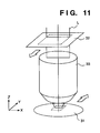
- a so-called stepper In this apparatus, as shown in Fig. 11, an exposure process is performed while synchronously moving a reticle 32 and a wafer 31 at a constant velocity, thereby realizing a chip size that cannot be realized by the conventional stepper.
- Fig. 11 shows the arrangement of a synchronous scan type reduction projection exposure apparatus.
- the wafer 31 and the reticle 32 are synchronously moved in opposite directions at a velocity ratio equal to a selected reduction ratio.
- light emitted by a light source (not shown) is converted into strip-shaped light L having a small width in the scan direction by a rectangular stop.
- the above-mentioned synchronous scan operation is performed while forming an image of a chip drawn on the reticle 32 at a desired position on the wafer 31 at a predetermined reduction ratio via a lens 33.
- the exposure operation of a chip size that cannot be realized by the conventional step-driving type exposure apparatus (stepper) can be attained.
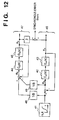
- Fig. 12 is a typical block diagram of a control system in the synchronous scan type exposure apparatus.
- a target state quantity (i.e., a target position in this case) with respect to a wafer stage 43 is generated by a target state quantity generating unit 41, and is supplied to a wafer control system 46.
- the target state quantity is also supplied to a target state quantity conversion unit 48.
- the target state conversion unit 48 multiplies the target state quantity with 1/ ⁇ (where ⁇ is the reduction ratio) to generate a target state quantity with respect to a reticle stage 45, and outputs the converted quantity to a reticle control system 47. In this manner, the synchronous target positions respectively for the wafer stage 43 and the reticle stage 45 are generated.
- a deviation e m between the target state quantity in the wafer control system 46 and a position X m of the wafer stage 43 is multiplied with 1/ ⁇ by a synchronous error correction unit 49, and is supplied to the reticle control system 47.
- a synchronous error e sync is suppressed.
- control system of the synchronous scan type exposure apparatus is a master-slave control system which has the wafer control system 46 as the master system and the reticle control system 47 as the slave system.
- a final performance index is given by a synchronous error e sync that is the deviation between the position X m of the wafer stage 43, and a value obtained by multiplying the position of the reticle stage 45 with ⁇ .
- problem (2) is a problem associated with the coupling method of the control systems, and problem (1) is most important. Therefore, the following description will be focused on technical problem (1), i.e., the technical problem upon performing high-precision scan control at high velocity.
- the minimum line width of a chip is about 250 nm in the case of a 256M DRAM, and a scan type semiconductor exposure apparatus must perform scan control while maintaining precision between the wafer and the reticle to be about a fraction of the minimum line width.
- a scan type semiconductor exposure apparatus must perform scan control while maintaining precision between the wafer and the reticle to be about a fraction of the minimum line width.
- the stage is moved to a desired position, and upon completion of settling, an exposure process is performed. Therefore, even when slight friction or the like is present within the step moving range, and the stage suffers slight velocity nonuniformity during traveling (although the alignment time is slightly prolonged), they do not adversely influence the yield.
- the presence of a factor that disturbs high-precision, constant-velocity movement such as friction within a scan region in other words, a factor that disturbs the synchronous relationship between the wafer and the reticle, distorts an exposed image and adversely influences the yield.
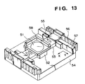
- a linear motor When a linear motor is used as a driving element, a method of assuring a long-stroke movable range using a plurality of voice coils or permanent magnets as stators is popularly used. This is for the following reason. That is, in the case of a moving magnet type motor in which the coil side serves as a stator, if a long-stroke- movable range is covered by a single voice coil, the driving current increases, and a problem of thermal deformation due to heat generated by the coil readily occurs. On the other hand, in the case of a moving coil type motor in which the permanent magnets serve as stators, it is difficult to manufacture a permanent magnet which can cover a long stroke.
- Fig. 13 shows an example of a non-contact movement type stage using a moving magnet type linear motor. The stage shown in Fig. 13 has degrees of freedom in two orthogonal, horizontal directions, and with this stage, the movement control of the wafer or reticle is performed.
- thrust nonuniformity is generated upon switching the stators.
- Figs. 14A and 14B show this state. More specifically, thrust nonuniformity is also generated depending on the stator position due to variations in magnetic force of coils or permanent magnets as a plurality of stators, variations in magnetic force depending on the stator position, or excitation timing shifts of coils when the stators comprise voice coils, and the like.
- the deviation upon scanning the stage at a constant velocity depends on the thrust nonuniformity, as shown in Fig. 15.
- the deviation nonuniformity increases. For this reason, when synchronous scan control is performed in such control system, its synchronous error also depends on the thrust nonuniformity. Therefore, the scan velocity cannot be sufficiently increased, and hence, the throughput of the apparatus cannot be improved.
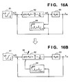
- a variable gain g(x) in a variable gain type PID compensator 62 is fixed to be 1, and a stage target state quantity for driving the stage on a scan traveling region at a constant velocity, i.e., a target position x r (t), is generated by a target state quantity generating unit 61, thus performing a so-called preliminary scan operation.
- a data sequence u(x) having the position of a stage 63 as an index is generated using a command value u(t) to the stage 63 and displacement data x(t) of the stage 63, and is stored in a memory unit 64.
- a command value u(t) to the stage 63
- displacement data x(t) of the stage 63 is stored in a memory unit 64.
- a gain table g(x) is generated by cutting the high-frequency components of the data sequence u(x) and then normalizing the data sequence u(x), thus updating data in the memory unit 64.
- the gain of the variable gain type PID compensator 62 is changed by a varying unit 65 on the basis of the gain table g(x).
- a normalization method a method of setting an expected value of g(x) to be 1, a method of giving a bias value to u(x) so that the maximum value of g(x) becomes 1, and the like may be used.
- a method of setting an expected value of g(x) to be 1 a method of giving a bias value to u(x) so that the maximum value of g(x) becomes 1, and the like may be used.
- the conventional technique suffers the following problems in the case of, e.g., the gain table look-up method.
- the local control characteristics largely vary in the conventional control apparatus which adopts the gain table look-up method.
- acceleration, constant-velocity scan, and deceleration operations are repeated in correspondence with the exposure regions of a plurality of chips arranged within the movable range of the stage. Therefore, when the local control system characteristics largely vary as in the conventional technique, the acceleration and deceleration times vary, and the throughput of the apparatus is considerably limited.
- the same problems are posed when the gain of the control system is changed by a function.
- the linear motor as the driving element will be described in detail below.
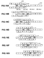
- Figs. 18A to 18G show an example of the arrangement of a poly-phase linear motor having a plurality of coils.
- reference numeral 212 denotes linear motor coils (stators), which are assigned Nos. 1 to 4 for the sake of convenience.
- Reference numeral 213 denotes movable magnets (movable members), which are arranged so that adjacent or opposing magnets have opposite polarities.
- the positions of the movable member 213 are detected by, e.g., Hall elements arranged in the coils, and by detecting the polarities (N and S poles) of the movable magnets 213, a predetermined coil is energized.
- Figs. 18A to 18G also show a method of selecting the coil to be energized. Note that marks ⁇ and ⁇ indicate the directions of currents to be supplied to the coils.
- the circuit arrangement for driving the poly-phase linear motor with the arrangement shown in Figs. 18A to 18G is described in Japanese Patent Laid-Open No. 1-298410.
- the thrusts generated by the respective coil portions are not always equal to each other.
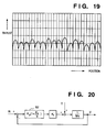
- Adjacent coils are normally arranged to be separated by a given gap. Due to the presence of the gap between adjacent coils, the thrust also varies depending on the position of the movable members, and consequently, a thrust distribution shown in Fig. 19 is normally obtained. Therefore, for example, when constant-velocity control of the movable members is to be performed, it is impossible to sufficiently reduce the control deviation or control error due to the influence of such thrust variation.
- Fig. 20 shows a velocity control system of a motor that constitutes a velocity feedback loop, and a PI (proportional + integral) compensator is arranged for the sake of simplicity. Also, K t is a torque constant, and M is the mass of a movable portion.
- control frequency range need only be broadened by increasing, e.g., the gain of the PI compensator.
- the expected control frequency range cannot always be obtained.
- the present invention provides a control apparatus and method as set out in the appended claims.
- the first embodiment of the present invention will be described below while taking as an example a wafer stage control system using a moving magnet type linear motor.
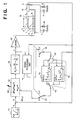
- reference numeral 1 denotes a stage in a synchronous scan type reduction projection exposure apparatus; 2, an anti-vibration table; 3, a wafer carried on the stage 1; 4, a movable member of a linear motor, which is fixed to the stage 1; 5, a stator of the linear motor, which is fixed to the anti-vibration table 2; 6, static pressure bearings; 7, dampers that act in their supporting direction with respect to the anti-vibration anti-vibration table 2; 8, springs for supporting the table 2; 9, a laser interferometer for measuring the position of the stage 1; 10, a mirror fixed on the stage 1 and adapted to reflect a laser beam emitted by the laser interferometer 9; 11, a target state quantity generating unit for generating a target position of the stage 1; 12, a PID compensator connected to the output terminal of a variable phase compensator 13; 13, a variable phase compensator corresponding one of the characteristic features of this embodiment; 14, a signal processing unit for a driving signal
- the stage 1 that carries the wafer 3 moves in a non-contact manner on the anti-vibration table 2 in the X-axis direction by the movable member 4, the stator 5, and the static pressure bearings 6.
- the anti-vibration table 2 is shielded from floor vibrations by the dampers 7 and the springs 8.
- a displacement x m of the mirror 10 on the stage 1 with respect to the anti-vibration table 2 is measured by the laser interferometer 9.
- a position deviation e is generated based on a target state quantity, i.e., a target position X r of the stage 1 generated by the target state quantity generating unit 11, and the displacement x m of the stage 1 measured by the laser interferometer 9, and is supplied to a so-called serial compensation unit constituted by the variable phase compensator 13 and the PID compensator 12.
- the characteristic of the compensator 12 is indicated by using corner frequency ⁇ i and ⁇ d as shown in Fig. 1.
- the output, u, from the serial compensation unit is supplied to the driver 21, and is current-amplified.
- the current output, i, from the driver 21 is supplied to the stator 5 of the linear motor.
- Fig. 1 is a block diagram showing the control arrangement of a precision control apparatus according to the first embodiment.
- the major features of the control system of the first embodiment are that the variable phase compensator 13 is arranged at the input side of the serial compensator constituted by the PID compensator 12, and the gain tables 15 and 16 corresponding to the driving directions, i.e., the forward and reverse directions, of the stage 1 are arranged.
- variable phase compensator 13 An improvement in control characteristics by the variable phase compensator 13 will be explained below.
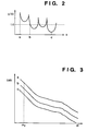
- Fig. 2 shows an example of a gain table formed by a preliminary scan operation.
- a command signal u to be supplied to the linear motor in a preliminary scan operation is subjected to filter processing so as to cut high frequency noise components, and thereafter, the processed signal is multiplied with a predetermined bias value so that the expected value becomes 1.
- Deviation nonuniformity caused by a thrust nonuniformity is generated upon switching coils or permanent magnets to be energized. Therefore, the deviation nonuniformity in a constant-speed scan operation has predetermined periodicity. This periodicity is represented by ⁇ g . Note that ⁇ g is as low as several rad/sec.
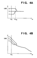
- Fig. 3 shows changes in gain of the open-loop transfer characteristics of the control system of the above-mentioned three points when the gains are changed by the conventional technique using the gain table shown in Fig. 2.
- the conventional technique since the entire gain characteristics of the system change up and down, local characteristic variations of the control system become very large.
- the angular frequency of the deviation nonuniformity to be removed by the gain of the table is ⁇ g , and is as low as several rad/sec, the characteristics in the high-frequency range are needlessly changed in the conventional technique.
- variable phase compensator 13 in place of changing the gain of the entire system, the variable phase compensator 13 given by formula (2) below is added to the compensation system: g(x) ⁇ lag + s ⁇ lag + s
- the phase lead frequency is changed by the gain g(x) of the table.
- the variable phase compensator serves as a phase lead-lag compensator when g ⁇ 1, or serves as a phase lag-lead compensator when g > 1.
- ⁇ lag indicates corner frequency.
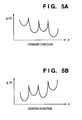
- Fig. 4A shows the gain characteristics of the variable phase compensator 13 at the above-mentioned three points. Although the gain in the low-frequency range including the angular frequency ⁇ g of the thrust nonuniformity is changed by the gain table, the gain in the high-frequency range is left unchanged.
- Fig. 4B shows the open-loop transfer characteristics of the control system when this variable phase compensator 13 is used. As shown in Fig. 4B, only the gain in the low-frequency range including the frequency ⁇ g of the thrust nonuniformity changes, and the characteristics in the high-frequency range are not influenced at all. Therefore, characteristic variations of the system due to the gain table can be minimized, and the deviation nonuniformity can also be suppressed.
- a preliminary scan operation is performed so as to form a gain table on the basis of the influence of the thrust nonuniformity. More specifically, the preliminary scan operation of the stage 1 is performed by assigning a target position X r so that a constant stage velocity is obtained in the entire movable region of the stage 1. At this time, the switches 17 and 18 are set at the p side.
- a forward preliminary scan operation is performed.
- the switches 19 and 20 are set at the f side.
- a control command signal u(t) in the forward scan operation obtained in this state and stage position information x(t) are supplied to the signal processing unit 14, and a table u(x m ) using the stage position x m as an index is formed based on the two signal sequences.
- the signal processing unit 14 performs filter processing and normalization processing for the table u(x m ), thus forming a forward gain table g f (x m ). This procedure for this process has already been described above with reference to Fig. 2.
- the gain table g f (x m ) is stored in the memory unit 15 corresponding to the forward feed direction.
- Figs. 5A and 5B respectively show the forward and reverse gain tables formed in this manner.
- the control characteristics especially at the end portion of the stage movable range deteriorate, and such deterioration adversely influences the throughput.
- this embodiment since this embodiment has a plurality of tables depending on the stage position, such dependence on the feed direction of the gain table can be appropriately coped with.
- the switches 17 and 18 are set at the s side, and a scan operation is performed. At this time, the switches 19 and 20 are switched to the f or r side depending on the feed direction. Then, tables values corresponding to the forward and reverse directions are looked up using the stage position x m as an index, and are transferred to the varying unit 22.
- the varying unit 22 changes the corner frequency of the variable phase compensator 13. In this embodiment, characteristic variations of the control system due to the table look-up operation can be minimized, and the deviation nonuniformity due to the thrust nonuniformity can be sufficiently removed, as has been described above with reference to Figs. 2 and 3 and Figs. 4A and 4B.
- variable phase compensator 13 can be easily constituted when the compensator 13 is approximately implemented using a digital filter which is obtained by discrete approximation at a predetermined sampling period, and is mounted using a microprocessor.
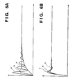
- Figs. 6A and 6B illustrate unit step responses of the stage control system at the three points a, b, and c shown in Fig. 2.
- Fig. 6A shows unit step responses in the conventional technique, and characteristic variations of the control system are very large due to the influence of the gain table. Therefore, when scan control is performed in practice using the conventional technique, the settling time considerably deteriorates in some shots, resulting in a low throughput.
- characteristic variations of the control system due to a gain variation can be minimized, and a high throughput can be obtained.
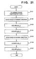
- step S101 the variable phase compensator 13 is fixed to be "1".
- step S102 the stage 1 is driven in the forward direction. Note that the switches 19 and 20 are set at the f side at this time, and a gain table is formed in the memory unit 15.
- step S103 the signal processing unit 14 acquires u at each position x m , and acquires u(x m ).
- the signal processing unit 14 performs filter processing and normalization processing for the obtained u(x m ) to acquire g f (x m ), which is stored in the memory unit 15.
- the switches 19 and 20 are set at the r side, and the same processing as in steps S102 to S104 is performed (steps S105, S106, and S107).
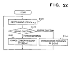
- step S121 the position information x m of the stage is fetched from the laser interferometer 9 upon driving the stage 1.
- step S122 the current driving direction of the stage 1 is discriminated. If the driving direction is the forward direction, the flow advances to step S123.
- step S123 the switches 19 and 20 are set at the f side, and the corner frequency is corrected using the table g f (x m ).
- step S124 the switches 19 and 20 are set at the r side, and the corner frequency is corrected using the table g r (x m ).
- the gain table g(x) is set so that its maximum value assumes "1"
- a phase lead-lag compensator is always constituted. Therefore, when only the gain in the low-frequency range is changed by the variable phase lead-lag compensator using the gain table normalized by g ⁇ 1, the phase compensation of the control system can be increased. That is, the stability of the control system can be improved by the variable phase lead-lag compensator.
- the control system of the wafer stage in the scan type exposure apparatus has been exemplified.
- the present invention can be similarly applied to any other apparatuses that require constant-velocity control with high precision, e.g., removal of cogging nonuniformity of a motor in constant-speed control of an image scanner or a copying machine, independently of 1-input/output systems or multi-input/output systems.
- the compensation system is constituted by a normal serial compensator using a PID compensator and a variable phase compensator.
- the serial compensator is not limited to the PID compensator, and the compensation system may be constituted using any other serial compensators.
- the present invention can be applied to any state quantities such as a displacement, velocity, and the like of the controlled object.
- the compensation system is constituted by two compensators, i.e., a normal serial compensator and a variable phase compensator.
- a portion of the normal serial compensator may directly constitute the variable phase compensator.
- a compensation system of a lower order can be constituted.
- the present invention is applied to the control system including only a serial compensator, i.e., a so-called single-degree-freedom control system.
- a serial compensator i.e., a so-called single-degree-freedom control system.
- the present invention is not limited to this.
- the present invention can be similarly applied to a two-degree-freedom control system, e.g., a control system having a feedforward system.
- variable phase compensation since the variable phase compensation is adopted, a control apparatus which can realize good control performance in the entire movable region of the controlled object while suppressing characteristic variations of the control system, and can remove the deviation nonunifority, even when variations due to a gain table or function are large by changing the time constant using the gain table and/or the function so as to remove deviation nonuniformity due to thrust nonuniformity of driving elements, can be realized.
- Fig. 7 shows the arrangement of a poly-phase linear motor control apparatus according to the second embodiment of the present invention.
- reference numeral 201 denotes a look-up table forming unit; and 202, a table look-up unit.
- Reference numeral 203 denotes a memory serving as a look-up table storing unit; 204, a control operation unit; and 205, a target position generating unit.
- the look-up table forming unit 201, the table look-up unit 202, the control operation unit 204, and the target position generating unit 205 are realized by a microprocessor 206 such as a CPU, DSP, or the like.
- a D/A converter 207 receives a command value from the microprocessor 206, converts it into an analog signal, and supplies the analog signal to an amplifier 208.
- a current control loop is constituted, and hence, the amplifier 208 serves as a current mode amplifier.
- a poly-phase linear motor 209 is driven by the amplifier 208, and the position of an object to be driven is detected by a position detector 210.
- the poly-phase linear motor 209 has the same arrangement as that shown in Figs. 18A to 18G used in the description of the prior art.
- the position detector 210 comprises a laser interferometer, but may comprise a linear encoder or the like.
- the control operation unit 204 performs a control compensation operation such as a PID operation using position information output from the position detector 210, and supplies the operation result to the D/A converter 207 as a current command value, thus constituting a feedback loop for performing position control.
- a control compensation operation such as a PID operation using position information output from the position detector 210
- a movable element of the poly-phase linear motor is moved at a constant velocity to a first position in accordance with a target value generated by the target position generating unit 205 (step S201).
- the movable member is driven to a second position by applying the same target value pattern as that used for actually driving the poly-phase linear motor (steps S202 and S203).
- the microprocessor 206 stores positions P n of the movable member and the differences between the target positions and the actual positions of the movable member, i.e., control deviations E n , in the memory 203 at predetermined periods (1 msec) (step S202).
- the storage operation in the memory ends.
- the positions and the control deviations stored in the memory 3 normally include high-frequency components represented by external noise. Including such high-frequency components in a table is not preferable since the control system is forced to perform an insignificant operation. In some cases, the operation of the control system may become unstable. Therefore, in this embodiment, the high-frequency components are removed using a high-frequency cutoff type linear phase filter (steps S204 to S206).
- the cutoff frequency of the filter is set to be lower than the lower limit of the control frequency band estimated from parameters of a control compensator included in the control operation unit 204.
- a 50th-order FIR filter given by equation (3) below is used, and its cutoff frequency is set to be 20 Hz.
- y is the output from the filter
- x is the input time sequence of the filter
- f is a coefficient of the filter
- n is time.
- the positions P n and the control deviations E n are subjected to the above-mentioned filter processing to obtain a position time sequence PF n and a control deviation time sequence EF n .
- the relationship between the position of the movable member of the poly-phase linear motor and the control deviation is formed as a table.
- Values in the position time sequence PF n subjected to the filter processing are checked one by one in turn, and every time the value increases by one unit (6), the value in the control deviation time sequence EF n is extracted and determined as a look-up table value (steps S207 to S209).
- one unit 6 represents the resolution (pitch) of the look-up table, and is set to be 0.1 mm in this embodiment. However, one unit 6 may be set to be sufficiently small as long as the memory capacity allows.
- a look-up table K m obtained by the processing performed so far is stored in the memory 203, and is looked up by the table look-up unit 202 as needed.
- the table look-up unit 202 will be described below.
- the table look-up unit 202 Upon execution of actual operations such as velocity control, alignment, and the like by driving the poly-phase linear motor, the table look-up unit 202 looks up the table in accordance with a rule represented by equations (4) below on the basis of position information p obtained by the position detector 210, thus obtaining a correction value k at that position.
- the position information p obtained by the position detector 210 is converted into a value an integer multiple of the pitch 6 of the table, and the converted value is used as an offset (index L) from the beginning of the look-up table in the memory, thereby obtaining a correction value k corresponding to the current position.
- the obtained correction value k is added to the calculation result of the control deviation in the control operation unit 204, and thereafter, the compensation calculation result such as PID calculation result is input as a manipulated variable, i.e., a control input to the D/A converter 207, thus driving the poly-phase linear motor.
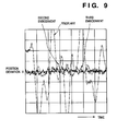
- Fig. 9 shows the position deviation in a steady state upon performing a constant-velocity driving operation in the system shown in Fig. 7, as compared to that in the prior art, so as to show the effect of the present invention.
- the position deviation caused by a conventional poly-phase linear motor driving apparatus is indicated by a dotted curve
- the position deviation caused by the present invention is indicated by a broken curve.
- the position deviation is suppressed by the present invention.
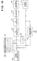
- Fig. 23 is a block diagram showing the control arrangement of a poly-phase linear motor according to the second embodiment of the present invention.
- reference numeral 203' denotes a look-up table stored in the memory 203.
- Reference numeral 202' denotes an index calculation unit included in the table look-up unit 202.
- the index calculation unit 202' calculates an index L on the basis of position information p supplied from the position detector 210 and the unit 6 of the look-up table 203'.
- a correction value stored at an address corresponding to the index L is read out from the look-up table 203', and is added to the control deviation.
- the look-up table forming unit 201 Upon forming a look-up table, the look-up table forming unit 201 generates correction values in the above-mentioned sequence, and registers them in the look-up table. Note that the correction value input from the look-up table 203' is fixed to be zero upon forming a look-up table.
- the look-up table is formed in accordance with the flow chart shown in Fig. 8.
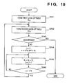
- Fig. 10 is a flow chart showing this procedure.
- a first look-up table K m is formed in accordance with the flow chart shown in Fig. 8 (step S241). As described in the second embodiment, a value obtained from the first look-up table K m is added to the control deviation to drive the motor. At this time, a second look-up table K' m is formed in accordance with the flow chart shown in Fig. 8 (step S242), and is added to the first look-up table K m in units of elements to obtain a new look-up table (steps S244 to S246).
- step S243 information which cannot be reflected in a table obtained by the N-th correction can be reflected in a table obtained by the (N+1)-th correction, and the position deviation suppression performance can be further improved.
- Fig. 9 also shows the position deviation waveform (solid curve) obtained when the table correction is performed three times. As can be seen from Fig. 9, the position deviation is further suppressed to 1/2 that obtained when no table correction is performed.
- the memory 203 such as a RAM or the like is used as the look-up table storing unit.
- the look-up table may be stored in a medium such as a magnetic disk or the like. Once the look-up table is formed, it need not be repetitively formed unless the characteristics of a mechanical system change. Therefore, the look-up table is loaded only once from the medium such as a magnetic disk that stores the look-up table upon starting up an equipment, and can be stored in, e.g., a RAM. After the poly-phase linear motor is driven over a long term, the look-up table may be automatically re-formed, thus correcting aging of the mechanical system.
- a poly-phase linear motor driving apparatus which can sufficiently remove thrust variations of a poly-phase linear motor in a system using the poly-phase linear motor can be provided.
- the drive control method and apparatus can be used in a semiconductor exposure apparatus for the manufacture of semiconductor devices.
- the accurate control of the relative movement of the mask and wafer allows for the fabrication of semiconductor devices having smaller line widths.
- the driving control is carried out during the exposure operation of the wafer to a pattern of the substrate.
- semiconductor devices can be fabricated from the wafer using conventional techniques e.g. etching of the exposed photo-resist on the wafer.
Landscapes
- Physics & Mathematics (AREA)
- General Physics & Mathematics (AREA)
- Engineering & Computer Science (AREA)
- Human Computer Interaction (AREA)
- Manufacturing & Machinery (AREA)
- Automation & Control Theory (AREA)
- Exposure And Positioning Against Photoresist Photosensitive Materials (AREA)
- Control Of Position Or Direction (AREA)
Claims (27)
- Regelungsvorrichtung zur Erzeugung eines Regelungsausgangssignals zur Regelung der Bewegung eines Objekts (1), wobei die Vorrichtung umfaßt:gekennzeichnet durcheine Erfassungseinrichtung (9, 10; 210) zur Erfassung einer Ist-Zustandsgröße des Regelungsobjekts,eine Erzeugungseinrichtung (11) zur Erzeugung einer Soll-Zustandsgröße des Regelungsobjekts,eine Regelungseinrichtung (12, 13, 21; 204, 207, 208) zur Bereitstellung des Regelungsausgangssignals auf der Grundlage der Ist-Zustandsgröße und der Soll-Zustandsgröße des Regelungsobjekts,eine Bestimmungseinrichtung zur Bestimmung eines Betriebszustands des Regelungsobjekts,eine Einstelleinrichtung (15, 16; 201, 203) zur Bereitstellung von Einstell-Informationen mit einer Tabelle von Einstell-Größen für jeden Betriebszustand, wobei jede Einstell-Größe einer Zustandsgröße des Regelungsobjekts entspricht, wobeidie Regelungseinrichtung (12, 13, 21; 204, 207, 208) auf die Einstelleinrichtung (15, 16; 201, 203) derart reagiert, daß sie das Regelungsausgangssignal auf der Grundlage der Einstell-Größe für den bestimmten Betriebszustand einstellt, der der Ist-Zustandsgröße entspricht.
- Vorrichtung nach Anspruch 1, wobei die Zustandsgröße mit dem Regelungsobjekt verbundene Positionsinformationen darstellt und der Betriebszustand eine Bewegungsrichtung des Regelungsobjekts darstellt.
- Vorrichtung nach Anspruch 1, wobei die Erfassungseinrichtung (9, 10; 210) zur Erfassung von mit dem Regelungsobjekt verbundenen Geschwindigkeitsinformationen eingerichtet ist, und die Bestimmungseinrichtung zur Bestimmung der Bewegungsrichtung des Regelungsobjekts eingerichtet ist.
- Vorrichtung nach einem der vorstehenden Ansprüche, wobei die Regelungseinrichtung (12, 13, 21; 204, 207, 208) auf die Einstelleinrichtung (15, 16; 201, 203) dahingehend reagiert, eine Phasenkompensation an dem Ausgangssignal auf der Grundlage der entsprechenden Einstell-Informationen zu ändern.
- Vorrichtung nach Anspruch 4, wobei die Regelungseinrichtung (12, 13, 21; 204, 207, 208) auf die Einstelleinrichtung (15, 16; 201, 203) dahingehend reagiert, eine Eckfrequenz der Phasenkompensation auf der Grundlage der entsprechenden Einstell-Informationen zu ändern.
- Vorrichtung nach einem der vorstehenden Ansprüche, wobei die Einstelleinrichtung (15, 16; 201, 203) eine Einstell-Informations-Erzeugungseinrichtung (14) zur Ermittlung einer Beziehung zwischen der Zustandsgröße des Regelungsobjekts und einer Regelungsgröße der Regelungseinrichtung (12, 13, 21; 204, 207, 208) in einer Betriebsart, bei der eine Einstellung durch die Einstelleinrichtung (15, 16; 201, 203) blockiert ist, und zur Erzeugung der Einstell-Informationen auf der Grundlage der ermittelten Beziehung und des Betriebszustands zu diesem Zeitpunkt aufweist.
- Vorrichtung nach Anspruch 2, wobei die Regelungseinrichtung (12, 13, 21; 204, 207, 208) zur Ansteuerung eines Linearmotors des Typs eingerichtet ist, der durch Schalten von Spulen angesteuert wird, denen entsprechend einem Zustand eines bewegbaren Teils Energie zuzuführen ist.
- Vorrichtung nach Anspruch 7, zusätzlich miteiner Ermittlungseinrichtung zur Ansteuerung des Linearmotors und zur Ermittlung von Regelungsabweichungen bei einer Vielzahl von Positionen des bewegbaren Teils, während eine Einstellung durch die Einstelleinrichtung blockiert ist, undeiner Informations-Erzeugungseinrichtung zur Erzeugung von Einstell-Informationen entsprechend jeder Position des bewegbaren Teils auf der Grundlage der durch die Ermittlungseinrichtung ermittelten Regelungsabweichungen.
- Vorrichtung nach Anspruch 8, wobeidie Ermittlungseinrichtung zur Ermittlung der Positionen des bewegbaren Teils und der Regelungsabweichungen als Zeitfolge-Daten eingerichtet ist unddie Informations-Erzeugungseinrichtung zur Erzeugung einer Nachschlag-Tabelle eingerichtet ist, die Regelungsabweichungen entsprechend den Positionen des bewegbaren Teils auf der Grundlage der Zeitfolge-Daten registriert.
- Vorrichtung nach Anspruch 9, wobei die Informations-Erzeugungseinrichtung zur Erzeugung der Nachschlag-Tabelle auf der Grundlage eines durch das Entfernen von Hochfrequenz-Komponenten von den Zeitfolge-Daten erhaltenen Ergebnisses eingerichtet ist.
- Vorrichtung nach Anspruch 10, wobei die Informations-Erzeugungseinrichtung ein phasenlineares Tiefpaßfilter zur Entfernung der Hochfrequenzkomponenten von den Zeitfolge-Daten aufweist, wobei die Grenzfrequenz des Filters niedriger eingestellt ist als die untere Grenze des Regelungsfrequenzbereichs eines Regelsystems.
- Vorrichtung nach Anspruch 7 miteiner Halteeinrichtung zum Halten einer ersten Nachschlag-Tabelle, die Einstell-Informationen entsprechend jeder Position des bewegbaren Teils des Linearmotors registriert,einer Nachschlag-Tabellen-Erzeugungseinrichtung zur Erzeugung einer zweiten Nachschlag-Tabelle auf der Grundlage von Zeitfolge-Daten von Regelungsabweichungen und Positionen des bewegbaren Teils, die als Ergebnis einer Regelung durch das Regelungsausgangssignal erhalten werden, undeiner Nachschlag-Tabellen-Korrektureinrichtung zur Korrektur der ersten Nachschlag-Tabelle auf der Grundlage der zweiten Nachschlag-Tabelle.
- Vorrichtung nach Anspruch 12, wobei die Halteeinrichtung darauf eingerichtet ist, die erste, durch eine mehrfach wiederholte Einstellung durch die Einstelleinrichtung erhaltene Nachschlag-Tabelle zu halten.
- Verfahren zur Regelung der Bewegung eines Objekts (1) mit den Schritten:Erfassen einer Ist-Zustandsgröße des Regelungsobjekts,Erzeugen einer Soll-Zustandsgröße des Regelungsobjekts,Bestimmen des Betriebszustands des Regelungsobjekts,Bereitstellen von Einstell-Informationen mit einer Tabelle von Einstell-Größen für jeden Betriebszustand, wobei jede Einstell-Größe einer Zustandsgröße des Regelungsobjekts entspricht, undErzeugen eines Regelungsausgangssignals auf der Grundlage der Ist-Zustandsgröße und der Soll-Zustandsgröße des Regelungsobjekts, wobei das Regelungsausgangssignal auf der Grundlage der Einstell-Informationen für den bestimmten Betriebszustand eingestellt ist, der der Ist-Zustandsgröße entspricht.
- Verfahren nach Anspruch 14, wobei es sich bei der Zustandsgröße um dem Regelungsobjekt zugehörige Positionsinformationen handelt und bei dem Betriebszustand um eine Bewegungsrichtung des Regelungsobjekts handelt.
- Verfahren nach Anspruch 14, wobei es sich bei der Zustandsgröße um dem Regelungsobjekt zugehörige Geschwindigkeitsinformationen handelt und bei dem Betriebszustand um die Bewegungsrichtung des Regelungsobjekts handelt.
- Verfahren nach einem der Ansprüche 14 bis 16, wobei eine Einstellung durch Ändern der Phasenkompensation an dem Ausgangssignal auf der Grundlage der entsprechenden Einstell-Informationen ausgeführt wird.
- Verfahren nach Anspruch 17, wobei eine Eckfrequenz der Phasenkompensation auf der Grundlage der entsprechenden Einstell-Informationen verändert wird.
- Verfahren nach einem der Ansprüche 14 bis 18, zusätzlich mit den Anfangs schrittenErmitteln einer Beziehung zwischen der Zustandsgröße des Regelungsobjekts und einer Regelungsgröße in einer Betriebsart, bei der eine Einstellung blockiert ist, undErzeugen der Einstell-Informationen auf der Grundlage der ermittelten Beziehung und dem Betriebszustand zu diesem Zeitpunkt.
- Verfahren nach Anspruch 15, wobei das Regelungsausgangssignal zum Ansteuern eines Linearmotors des Typs eingerichtet ist, der durch Schalten von Spulen angesteuert wird, denen entsprechend einem Zustand eines bewegbaren Teils Energie zuzuführen ist.
- Verfahren nach Anspruch 20, zusätzlich mit den Schritten:Ansteuern des Linearmotors und Ermitteln von Regelungsabweichungen bei einer Vielzahl von Positionen des bewegbaren Teils, während eine Einstellung blockiert ist, undErzeugen von Einstell-Informationen entsprechend jeder Position des bewegbaren Teils auf der Grundlage der während der Ermittlung ermittelten Regelungsabweichungen.
- Verfahren nach Anspruch 21, wobeibei dem Ermitteln die Positionen des bewegbaren Teils und die Regelungsabweichungen als Zeitfolge-Daten ermittelt werden undbei dem Erzeugen von Einstell-Informationen eine Nachschlag-Tabelle erzeugt wird, die Regelungsabweichungen entsprechend der Position des bewegbaren Teils auf der Grundlage der Zeitfolge-Daten registriert.
- Verfahren nach Anspruch 22, wobei die Erzeugung der Nachschlag-Tabelle ein Entfernen von Hochfrequenz-Komponenten von den Zeitfolge-Daten umfaßt.
- Verfahren nach Anspruch 23, wobei die Hochfrequenz-Komponenten von den Zeitfolge-Daten unter Verwendung eines phasen linearen Tiefpaßfilters entfernt werden und die Grenzfrequenz des Filters niedriger eingestellt ist als die unterr Grenze des Regelungsfrequenzbereichs eines Regelsystems.
- Verfahren nach Anspruch 20, zusätzlich mit den Schritten:Halten einer ersten Nachschlag-Tabelle, die Einstell-Informationen entsprechend jeder Position des bewegbaren Teils des Linearmotors registriert,Erzeugen einer zweiten Nachschlag-Tabelle auf der Grundlage von Zeitfolge-Daten von Regelungsabweichungen und Positionen des bewegbaren Teils, die als ein Ergebnis einer Regelung durch das Regelungsausgangssignal erhalten werden, undKorrigieren der ersten Nachschlag-Tabelle auf der Grundlage der zweiten Nachschlag-Tabelle.
- Verfahren nach Anspruch 25, wobei das Halten der ersten Nachschlag-Tabelle durch mehrfaches Wiederholen einer Einstellung erhalten wird.
- Verfahren einer Fertigung einer Halbleitervorrichtung unter Verwendung des Ansteuerregelungsverfahren nach einem der Ansprüche 14 bis 26 zur Regelung eines synchronen Abtastens eines Wafers und einer Maske, während der der Wafer über ein Maskenmuster belichtet wird, und zur Herstellung einer Halbleitervorrichtung unter Verwendung des Wafers.
Applications Claiming Priority (4)
| Application Number | Priority Date | Filing Date | Title |
|---|---|---|---|
| JP248266/95 | 1995-09-04 | ||
| JP24826695A JP3320276B2 (ja) | 1995-09-04 | 1995-09-04 | 精密制御装置 |
| JP32787295A JP3387715B2 (ja) | 1995-11-24 | 1995-11-24 | 多相リニアモータ制御装置 |
| JP327872/95 | 1995-11-24 |
Publications (2)
| Publication Number | Publication Date |
|---|---|
| EP0762255A1 EP0762255A1 (de) | 1997-03-12 |
| EP0762255B1 true EP0762255B1 (de) | 1999-03-17 |
Family
ID=26538682
Family Applications (1)
| Application Number | Title | Priority Date | Filing Date |
|---|---|---|---|
| EP96306378A Expired - Lifetime EP0762255B1 (de) | 1995-09-04 | 1996-09-03 | Einrichtung zur Antriebsregelung |
Country Status (4)
| Country | Link |
|---|---|
| US (1) | US5757149A (de) |
| EP (1) | EP0762255B1 (de) |
| KR (1) | KR100226599B1 (de) |
| DE (1) | DE69601763T2 (de) |
Cited By (1)
| Publication number | Priority date | Publication date | Assignee | Title |
|---|---|---|---|---|
| TWI488016B (zh) * | 2012-11-16 | 2015-06-11 | 唐明中 | 可攜式遠端互動系統 |
Families Citing this family (40)
| Publication number | Priority date | Publication date | Assignee | Title |
|---|---|---|---|---|
| US5874820A (en) | 1995-04-04 | 1999-02-23 | Nikon Corporation | Window frame-guided stage mechanism |
| US5528118A (en) * | 1994-04-01 | 1996-06-18 | Nikon Precision, Inc. | Guideless stage with isolated reaction stage |
| US6989647B1 (en) * | 1994-04-01 | 2006-01-24 | Nikon Corporation | Positioning device having dynamically isolated frame, and lithographic device provided with such a positioning device |
| US7365513B1 (en) | 1994-04-01 | 2008-04-29 | Nikon Corporation | Positioning device having dynamically isolated frame, and lithographic device provided with such a positioning device |
| TW318255B (de) | 1995-05-30 | 1997-10-21 | Philips Electronics Nv | |
| JP3501559B2 (ja) * | 1995-06-27 | 2004-03-02 | キヤノン株式会社 | リニア・モータ装置 |
| JP4039728B2 (ja) * | 1998-03-13 | 2008-01-30 | オリエンタルモーター株式会社 | ステッピングモータの制御装置 |
| US6260282B1 (en) * | 1998-03-27 | 2001-07-17 | Nikon Corporation | Stage control with reduced synchronization error and settling time |
| US6037737A (en) * | 1998-04-30 | 2000-03-14 | Trw Inc. | Simple friction-compensating control algorithm for high precision mechanisms |
| JPH11354417A (ja) | 1998-06-11 | 1999-12-24 | Canon Inc | 走査型露光装置およびこれを用いたデバイス製造方法ならびにステージ制御装置 |
| US6144118A (en) * | 1998-09-18 | 2000-11-07 | General Scanning, Inc. | High-speed precision positioning apparatus |
| JP3595708B2 (ja) * | 1998-10-30 | 2004-12-02 | キヤノン株式会社 | 露光装置、デバイス製造方法および制御方法 |
| US6487458B1 (en) | 1999-08-31 | 2002-11-26 | Delphi Technologies, Inc. | Adaptive closed-loop servo control |
| US6573976B2 (en) | 2000-10-04 | 2003-06-03 | Canon Kabushiki Kaisha | Exposure apparatus, exposure method, and semiconductor device manufacturing method |
| EP1267213B1 (de) * | 2001-06-13 | 2006-09-20 | ASML Netherlands B.V. | Lithographischer Projektionsapparat |
| JP3870058B2 (ja) * | 2001-10-05 | 2007-01-17 | キヤノン株式会社 | スキャン露光装置及び方法並びにデバイスの製造方法 |
| JP3963426B2 (ja) * | 2001-11-28 | 2007-08-22 | キヤノン株式会社 | ステージ装置および露光装置 |
| US6922025B2 (en) * | 2002-02-21 | 2005-07-26 | Anorad Corporation | Zero ripple linear motor system |
| JP3907566B2 (ja) * | 2002-09-27 | 2007-04-18 | キヤノン株式会社 | 位置決め装置における測定手段を初期化する方法 |
| US6949896B2 (en) * | 2002-12-03 | 2005-09-27 | Ricoh Company, Limited | Apparatus for and method of driving motor to move object at a constant velocity |
| US7119511B2 (en) | 2003-04-11 | 2006-10-10 | International Business Machines Corporation | Servo system for a two-dimensional micro-electromechanical system (MEMS)-based scanner and method therefor |
| JP4315420B2 (ja) * | 2003-04-18 | 2009-08-19 | キヤノン株式会社 | 露光装置及び露光方法 |
| NL1027851C2 (nl) * | 2004-12-22 | 2006-06-27 | Assembleon Nv | Werkwijze voor het regelen van een dynamisch systeem alsmede een dergelijke inrichting. |
| US7265813B2 (en) * | 2004-12-28 | 2007-09-04 | Asml Netherlands B.V. | Lithographic apparatus and device manufacturing method |
| US20060170382A1 (en) * | 2005-01-28 | 2006-08-03 | Nikon Corporation | Linear motor force ripple identification and compensation with iterative learning control |
| US7253580B2 (en) * | 2005-05-06 | 2007-08-07 | Marvell International Technology Ltd. | Method and apparatus for adaptive motor speed control |
| US20070206456A1 (en) * | 2005-09-30 | 2007-09-06 | Sullivan Jeffrey S | Trajectory mapping for improved motion-system jitter while minimizing tracking error |
| US7468589B2 (en) * | 2006-01-13 | 2008-12-23 | Asml Netherlands B.V. | Lithographic apparatus having a controlled motor, and motor control system and method |
| CA2637582A1 (en) | 2006-02-16 | 2007-08-30 | Kadant Inc. | Linear traversing carriage incorporating an air gap inductive motivator |
| US7453228B2 (en) * | 2006-04-07 | 2008-11-18 | Asml Netherlands B.V. | Method for controlling a positioning device, positioning device, and lithographic apparatus provided with a positioning device |
| US7818073B2 (en) * | 2006-04-20 | 2010-10-19 | Asml Netherlands B.V. | Method for obtaining improved feedforward data, a lithographic apparatus for carrying out the method and a device manufacturing method |
| CN100593767C (zh) * | 2006-06-30 | 2010-03-10 | 深圳市大族激光科技股份有限公司 | 电容传感器的控制方法 |
| US8267388B2 (en) * | 2007-09-12 | 2012-09-18 | Xradia, Inc. | Alignment assembly |
| US8452424B2 (en) * | 2008-03-05 | 2013-05-28 | National Univeristy Corporation Nagoya Institute of Technology | Moving object feed-forward control method |
| NL2003331A (en) * | 2008-09-02 | 2010-03-12 | Asml Netherlands Bv | Device manufacturing method, control system, computer program and computer-readable medium. |
| US8649885B2 (en) * | 2008-11-25 | 2014-02-11 | Nikon Corporation | Frequency selective iterative learning control system and method for controlling errors in stage movement |
| JP5308249B2 (ja) * | 2009-06-22 | 2013-10-09 | 三菱重工業株式会社 | サーボ制御装置 |
| NL2006981A (en) * | 2010-07-26 | 2012-01-30 | Asml Netherlands Bv | Position control system, lithographic apparatus, and method to control a position of a movable object. |
| EP3363085B1 (de) * | 2015-10-16 | 2023-05-10 | Thorlabs, Inc. | Linearmotor zur schnellen abstimmung eines laserresonator |
| JP7645658B2 (ja) * | 2021-02-24 | 2025-03-14 | キヤノン株式会社 | 制御装置、位置決め装置、リソグラフィー装置および物品製造方法 |
Family Cites Families (17)
| Publication number | Priority date | Publication date | Assignee | Title |
|---|---|---|---|---|
| JPS58116735A (ja) * | 1981-12-29 | 1983-07-12 | Canon Inc | 投影焼付方法 |
| JPS60168149A (ja) * | 1984-02-13 | 1985-08-31 | Canon Inc | 位置合わせ信号処理装置 |
| JPS6115341A (ja) * | 1984-07-02 | 1986-01-23 | Canon Inc | ウエハプロ−バ |
| US4747608A (en) * | 1984-10-30 | 1988-05-31 | Canon Kabushiki Kaisha | Wafer chuck |
| US4870288A (en) * | 1986-04-01 | 1989-09-26 | Canon Kabushiki Kaisha | Alignment method |
| US4714400A (en) * | 1986-04-14 | 1987-12-22 | Ibm Corporation | Plural robotic drive |
| JPH01298410A (ja) * | 1988-05-27 | 1989-12-01 | Canon Inc | 位置決めテーブル装置 |
| NL8902471A (nl) * | 1989-10-05 | 1991-05-01 | Philips Nv | Tweetraps positioneerinrichting. |
| US5216590A (en) * | 1990-07-13 | 1993-06-01 | Seiko Seiki Kabushiki Kaisha | Contactless guided positioning table |
| JP2864060B2 (ja) * | 1991-09-04 | 1999-03-03 | キヤノン株式会社 | 縮小投影型露光装置及び方法 |
| DE69322983T2 (de) * | 1992-02-21 | 1999-07-15 | Canon K.K., Tokio/Tokyo | System zum Steuern von Trägerplatten |
| JP3217522B2 (ja) * | 1992-03-02 | 2001-10-09 | キヤノン株式会社 | 精密位置決め装置 |
| JP3002351B2 (ja) * | 1993-02-25 | 2000-01-24 | キヤノン株式会社 | 位置合わせ方法および装置 |
| DE69412719T2 (de) * | 1993-06-24 | 1999-02-18 | Canon K.K., Tokio/Tokyo | Steuerung für einen mehrphasigen Motor |
| JPH07161798A (ja) * | 1993-12-06 | 1995-06-23 | Canon Inc | 位置決めテーブル装置 |
| US5609136A (en) * | 1994-06-28 | 1997-03-11 | Cummins Engine Company, Inc. | Model predictive control for HPI closed-loop fuel pressure control system |
| US5557156A (en) * | 1994-12-02 | 1996-09-17 | Digital Instruments, Inc. | Scan control for scanning probe microscopes |
-
1996
- 1996-09-03 EP EP96306378A patent/EP0762255B1/de not_active Expired - Lifetime
- 1996-09-03 DE DE69601763T patent/DE69601763T2/de not_active Expired - Lifetime
- 1996-09-03 KR KR1019960037952A patent/KR100226599B1/ko not_active Expired - Fee Related
- 1996-09-04 US US08/697,950 patent/US5757149A/en not_active Expired - Lifetime
Cited By (1)
| Publication number | Priority date | Publication date | Assignee | Title |
|---|---|---|---|---|
| TWI488016B (zh) * | 2012-11-16 | 2015-06-11 | 唐明中 | 可攜式遠端互動系統 |
Also Published As
| Publication number | Publication date |
|---|---|
| KR100226599B1 (ko) | 1999-10-15 |
| DE69601763T2 (de) | 1999-09-09 |
| US5757149A (en) | 1998-05-26 |
| KR970018132A (ko) | 1997-04-30 |
| DE69601763D1 (de) | 1999-04-22 |
| EP0762255A1 (de) | 1997-03-12 |
Similar Documents
| Publication | Publication Date | Title |
|---|---|---|
| EP0762255B1 (de) | Einrichtung zur Antriebsregelung | |
| EP1970941B1 (de) | Trägerplattensystem zur Verwendung in einem Belichtungsgerät | |
| US6714842B1 (en) | Synchronous position control apparatus and method | |
| US6130517A (en) | Magnetic actuator producing large acceleration on fine stage and low RMS power gain | |
| US6881963B2 (en) | Vibration control of an object | |
| US6286644B1 (en) | Active vibration isolator, exposure apparatus, exposure method and device manufacturing method | |
| US6473159B1 (en) | Anti-vibration system in exposure apparatus | |
| US5504407A (en) | Stage driving system | |
| US5511930A (en) | Precision positioning apparatus | |
| JP2964915B2 (ja) | レンズ駆動制御装置 | |
| JP4209121B2 (ja) | デュアル分離されたシステムを有するリソグラフィーツールおよびそれを構成する方法 | |
| US8140288B2 (en) | On-machine methods for identifying and compensating force-ripple and side-forces produced by actuators on a multiple-axis stage | |
| US6903806B2 (en) | Stage control apparatus, exposure apparatus, and device manufacturing method | |
| US7016049B2 (en) | Alignment apparatus, control method therefor, exposure apparatus, device manufacturing method, semiconductor manufacturing factory, and exposure apparatus maintenance method | |
| US20070097340A1 (en) | Active damper with counter mass to compensate for structural vibrations of a lithographic system | |
| US5545962A (en) | Positioning system | |
| JP3320276B2 (ja) | 精密制御装置 | |
| US6448723B1 (en) | Stage system and exposure apparatus | |
| EP1361486B1 (de) | Mechanismus für ein bewegliches Teil und Steuerungsverfahren für den selben | |
| US5714860A (en) | Stage device capable of applying a damping force to a movable member | |
| US20030097205A1 (en) | Control scheme and system for active vibration isolation | |
| US7583361B2 (en) | System for controlling a dual mover assembly for an exposure apparatus | |
| US11112705B2 (en) | Motor, dual stroke stage and lithographic apparatus | |
| JP4841008B2 (ja) | 移動体機構 | |
| JP2001332467A (ja) | ステージ装置、露光装置およびデバイス製造方法 |
Legal Events
| Date | Code | Title | Description |
|---|---|---|---|
| PUAI | Public reference made under article 153(3) epc to a published international application that has entered the european phase |
Free format text: ORIGINAL CODE: 0009012 |
|
| AK | Designated contracting states |
Kind code of ref document: A1 Designated state(s): DE FR GB NL |
|
| 17P | Request for examination filed |
Effective date: 19970723 |
|
| 17Q | First examination report despatched |
Effective date: 19970918 |
|
| GRAG | Despatch of communication of intention to grant |
Free format text: ORIGINAL CODE: EPIDOS AGRA |
|
| GRAG | Despatch of communication of intention to grant |
Free format text: ORIGINAL CODE: EPIDOS AGRA |
|
| GRAH | Despatch of communication of intention to grant a patent |
Free format text: ORIGINAL CODE: EPIDOS IGRA |
|
| GRAH | Despatch of communication of intention to grant a patent |
Free format text: ORIGINAL CODE: EPIDOS IGRA |
|
| GRAA | (expected) grant |
Free format text: ORIGINAL CODE: 0009210 |
|
| AK | Designated contracting states |
Kind code of ref document: B1 Designated state(s): DE FR GB NL |
|
| REF | Corresponds to: |
Ref document number: 69601763 Country of ref document: DE Date of ref document: 19990422 |
|
| ET | Fr: translation filed | ||
| PLBE | No opposition filed within time limit |
Free format text: ORIGINAL CODE: 0009261 |
|
| STAA | Information on the status of an ep patent application or granted ep patent |
Free format text: STATUS: NO OPPOSITION FILED WITHIN TIME LIMIT |
|
| 26N | No opposition filed | ||
| REG | Reference to a national code |
Ref country code: GB Ref legal event code: IF02 |
|
| PGFP | Annual fee paid to national office [announced via postgrant information from national office to epo] |
Ref country code: GB Payment date: 20080911 Year of fee payment: 13 |
|
| GBPC | Gb: european patent ceased through non-payment of renewal fee |
Effective date: 20090903 |
|
| PG25 | Lapsed in a contracting state [announced via postgrant information from national office to epo] |
Ref country code: GB Free format text: LAPSE BECAUSE OF NON-PAYMENT OF DUE FEES Effective date: 20090903 |
|
| PGFP | Annual fee paid to national office [announced via postgrant information from national office to epo] |
Ref country code: DE Payment date: 20140930 Year of fee payment: 19 Ref country code: NL Payment date: 20140804 Year of fee payment: 19 |
|
| PGFP | Annual fee paid to national office [announced via postgrant information from national office to epo] |
Ref country code: FR Payment date: 20140924 Year of fee payment: 19 |
|
| REG | Reference to a national code |
Ref country code: DE Ref legal event code: R119 Ref document number: 69601763 Country of ref document: DE |
|
| REG | Reference to a national code |
Ref country code: NL Ref legal event code: MM Effective date: 20151001 |
|
| REG | Reference to a national code |
Ref country code: FR Ref legal event code: ST Effective date: 20160531 |
|
| PG25 | Lapsed in a contracting state [announced via postgrant information from national office to epo] |
Ref country code: DE Free format text: LAPSE BECAUSE OF NON-PAYMENT OF DUE FEES Effective date: 20160401 |
|
| PG25 | Lapsed in a contracting state [announced via postgrant information from national office to epo] |
Ref country code: FR Free format text: LAPSE BECAUSE OF NON-PAYMENT OF DUE FEES Effective date: 20150930 Ref country code: NL Free format text: LAPSE BECAUSE OF NON-PAYMENT OF DUE FEES Effective date: 20151001 |