EP0762310B1 - Système d'échange de données comportant une pluralité de porteurs de données - Google Patents
Système d'échange de données comportant une pluralité de porteurs de données Download PDFInfo
- Publication number
- EP0762310B1 EP0762310B1 EP96202413A EP96202413A EP0762310B1 EP 0762310 B1 EP0762310 B1 EP 0762310B1 EP 96202413 A EP96202413 A EP 96202413A EP 96202413 A EP96202413 A EP 96202413A EP 0762310 B1 EP0762310 B1 EP 0762310B1
- Authority
- EP
- European Patent Office
- Prior art keywords
- signal
- identification
- data carriers
- source separation
- filtering
- Prior art date
- Legal status (The legal status is an assumption and is not a legal conclusion. Google has not performed a legal analysis and makes no representation as to the accuracy of the status listed.)
- Expired - Lifetime
Links
Images


Classifications
-
- H—ELECTRICITY
- H04—ELECTRIC COMMUNICATION TECHNIQUE
- H04B—TRANSMISSION
- H04B7/00—Radio transmission systems, i.e. using radiation field
- H04B7/24—Radio transmission systems, i.e. using radiation field for communication between two or more posts
- H04B7/26—Radio transmission systems, i.e. using radiation field for communication between two or more posts at least one of which is mobile
-
- G—PHYSICS
- G06—COMPUTING OR CALCULATING; COUNTING
- G06K—GRAPHICAL DATA READING; PRESENTATION OF DATA; RECORD CARRIERS; HANDLING RECORD CARRIERS
- G06K7/00—Methods or arrangements for sensing record carriers, e.g. for reading patterns
- G06K7/10—Methods or arrangements for sensing record carriers, e.g. for reading patterns by electromagnetic radiation, e.g. optical sensing; by corpuscular radiation
- G06K7/10009—Methods or arrangements for sensing record carriers, e.g. for reading patterns by electromagnetic radiation, e.g. optical sensing; by corpuscular radiation sensing by radiation using wavelengths larger than 0.1 mm, e.g. radio-waves or microwaves
- G06K7/10019—Methods or arrangements for sensing record carriers, e.g. for reading patterns by electromagnetic radiation, e.g. optical sensing; by corpuscular radiation sensing by radiation using wavelengths larger than 0.1 mm, e.g. radio-waves or microwaves resolving collision on the communication channels between simultaneously or concurrently interrogated record carriers.
- G06K7/10029—Methods or arrangements for sensing record carriers, e.g. for reading patterns by electromagnetic radiation, e.g. optical sensing; by corpuscular radiation sensing by radiation using wavelengths larger than 0.1 mm, e.g. radio-waves or microwaves resolving collision on the communication channels between simultaneously or concurrently interrogated record carriers. the collision being resolved in the time domain, e.g. using binary tree search or RFID responses allocated to a random time slot
- G06K7/10059—Methods or arrangements for sensing record carriers, e.g. for reading patterns by electromagnetic radiation, e.g. optical sensing; by corpuscular radiation sensing by radiation using wavelengths larger than 0.1 mm, e.g. radio-waves or microwaves resolving collision on the communication channels between simultaneously or concurrently interrogated record carriers. the collision being resolved in the time domain, e.g. using binary tree search or RFID responses allocated to a random time slot transponder driven
-
- G—PHYSICS
- G06—COMPUTING OR CALCULATING; COUNTING
- G06K—GRAPHICAL DATA READING; PRESENTATION OF DATA; RECORD CARRIERS; HANDLING RECORD CARRIERS
- G06K7/00—Methods or arrangements for sensing record carriers, e.g. for reading patterns
- G06K7/0008—General problems related to the reading of electronic memory record carriers, independent of its reading method, e.g. power transfer
Definitions
- the invention relates to a data exchange system. comprising a base station and at least one data carrier coupled to each other through wireless links to exchange data, the station comprising transmission means and reception means for respectively interrogating at least one data carrier and to receive, in response, a signal of identification issued by the data carrier questioned, the data carrier comprising transmission / reception means.
- the invention also relates to a base station.
- Such systems are used, for example, in controlling people to access premises, to vehicle identification, for the identification of goods, or more generally to identify any badge or another portable device used to recognize the wearer.
- the system includes a station basic coupled to the data carrier, for example a badge.
- a station basic coupled to the data carrier, for example a badge.
- the badge includes a memory, possibly programmable, in which stores content, including an identifier, allowing identify the person, animal or object wearing the badge.
- the badge is interrogated by the base station in sending an interrogation signal.
- the badge returns in response a return signal which contains the identifier contained in the badge.
- the base station demodulates and decodes this return signal, and, if the badge is recognized and accepted, the base station validates this recognition and take appropriate action.
- US patent specification 5,349,355 discloses a system identification including an interrogation station which can operate simultaneously with a plurality of badges to be identified.
- the principle implemented in this document is a time allocation plurality of slots for identification signals badges.
- the interrogating station transmits a signal question mark which it repeats sequentially to different modulation frequencies.
- a badge recognizes a frequency of particular modulation of the interrogating station, it responds by transmitting an identification signal at a code frequency particular during a particular broadcast slot.
- One drawback of this system is that it requires the badges to be provided with means specific complex to identify the modulation frequency of the interrogation signal and spot the niche of sound emission identification signal.
- Another disadvantage of this system is introduce a delay in the badge identification process, since the badge must wait for a particular time slot for issue its identification signal.
- the object of the invention is therefore to propose a system data exchange to quickly identify and simultaneously a plurality of data carriers, without complicating the structure of the data carrier, avoiding any protocol although the badges respond simultaneously, the system more reliable, even in the presence of noise high ambient.
- the station's reception means include a device for source separation to process dependent mix signals mixtures of identification signals emitted by carriers of data, said source separation device comprising filtering means for filtering said mixing signals to using filter coefficients, means of summing the filtered mixing signals, means for adapting them filter coefficients, the reception means comprising several demodulation units placed either at the output or at input source separation means, reception means delivering estimated identification signals for said carriers of data to be connected simultaneously.
- the badges In response to the interrogation signal from the station the badges respond by each sending a return signal modulated by their own identifier. Mixed signals, from all the badges issuing simultaneously, are then separated in the base station by applying a separation technique sources. Complex procedures for multiple interrogations followed confirmation responses are no longer required. In addition the system is much more robust to ambient noise which allows increase the recognition distances between the base station and the badge. In addition, the system can reduce consumption of energy required for operation.
- Wireless links can be diverse, for example infrared links, radio frequency links, ultrasonic connections. To each particular type of connection without wire, the system has specific input / output means for transmission and reception of exchanged signals. So, it will be antennas for radio frequency links, transducers transmitter / receiver for ultrasonic connections, or transmitters and light receivers for infrared links.
- the separation device sources either between the demodulation units and the means input reception specific to each type of link, i.e. after the demodulation units.
- the device source separation provides a modulated estimation signal depending on the identification signal of the data carrier.
- the source separation device provides directly the estimated identification signal.
- mixtures of signals arriving at the input of the source separation are instantaneous linear mixtures in the case of amplitude modulated signals.
- the source separation device may have a direct structure, a recursive structure or a mixed structure combining a partially direct structure and a partially recursive structure. All these structures make intervene filter coefficients applied to the different signals.
- the system calculates the filter coefficients itself necessary to perform signal separation.
- FIG. 3 represents a known system for exchanging data. It includes a base station 1 which receives from a carrier data 2, for example a TAG badge, an identification signal containing an ID identifier. The connection between the badge and the base station operates over a wireless link using a carrier modulated by the identification signal.
- the base station includes, in series, a 3 EXTRACT module for extracting the badge identifier, a 5 VALID validation module the identifier, and an actuator module 7 ACT which performs an action, for example opening an access to a place with reserved access.
- Figure 1 shows part of a known system data exchange. It includes the extraction module 3 and the badge 2 which must be identified when it is in the field of the base station.
- the extraction module includes transmission means comprising an oscillator 10 provided with an antenna 11, for example with an inductive effect.
- Badge 2 has a reception antenna 21a and a transmission antenna 21b associated with a processor 23 PROCES which is connected to storage means MEM 22 providing data. This data is for example a ID identifier specific to the badge.
- the extraction module includes also reception means 18 comprising an antenna reception 13 associated with a demodulation unit 12 DEMOD followed a DECOD 14 decoding unit. The modulated signal, received by antenna 13 in the base station is demodulated in the demodulation 12 which supplies the demodulated signal to the decoding unit 14 which delivers the badge ID identifier.
- the base station must identify the ID identifier contained in the badge so as either to give to the individual wearing the badge the authorization provided in this case, either to be prohibited authorization in the event of non-recognition. It can also be good recognition of an object or an animal training the triggering of actions planned in such a case.
- the oscillator 10 transmits through the antenna 11 a signal which arrives by a wireless link to the receiving antenna 21a of the badge, when it is placed within the scope of the base station.
- the processor 23 extracts from the received signal, by example, a clock rate and different control signals for operating and addressing memory 22 (connection 24).
- this operating mode can only be valid if there is only one badge in communication with the base station at a given time. Indeed, when at least two badges require simultaneously to be identified, the interrogation signal emitted by antenna 11 simultaneously interrogates all badges that respond at the same time, which means that the modulated signals re-emitted by the badges arrive mixed on the antenna 13.
- FIG. 2 represents the system according to the invention in the case, given by way of example, where the source separation device 15 is placed after the demodulation units and being limited to two badges 2 1 , 2 2 requiring simultaneously to be put in communication with the base station.
- the extraction means 3 comprise two reception antennas 13 1 , 13 2 respectively joined to two demodulation units 12 1 , 12 2 .
- Each reception antenna 13 1 , 13 2 receives signals from the two badges 2 1 , 2 2 in the form of mixtures of two modulated signals each containing an identification signal X 1 (t) or X 2 (t).
- the mixing signals are demodulated in the demodulation means 12 1 and 12 2 which supply demodulated signals E 1 (t) and E 2 (t) which are subjected to the action of the SEPAR device 15 for source separation.
- the latter delivers estimates X and 1 ( t ) and X and 2 ( t ) of the original signals X 1 (t) and X 2 (t) emitted by the badges by modulation of a carrier.
- the estimated signals X and 1 ( t ) and X and 2 ( t ) are decoded in the decoding means 14 1 and 14 2 to provide the identifiers ID 1 and ID 2 of the two badges.
- the filtering set used in the source separation device may, in in the general case, be formed of cells operating a filtering adaptive, and, in special cases, be formed of cells each implementing a single filter coefficient called then separation coefficient.
- a combination of these two types filtering is possible, a channel applying adaptive filtering with several coefficients and another way applying only one separation coefficient.
- the source separation device comprises cells each implementing a separation coefficient.
- the source separation then carried out by the source separation device 15 can be written in the form: for a direct structure, and for a recursive structure.
- the coefficients C ki , d ki are filter coefficients called separation coefficients which are calculated in real time by the source separation device.
- the example given concerns signals modulated by amplitude modulation.
- modulations for example frequency or phase modulation, can be processed similar.
- FIG. 4 represents another embodiment of the receiving means 18.
- the separation device 15 of sources is arranged at the output of the antennas, in front of the means demodulation.
- the separation thus relates to signals of modulated mixtures dependent on mixtures of identification signals data carriers, demodulation only taking place when the mixed signals have been separated.
- FIG. 5 relates, by way of example, to the case of three badges for the embodiment of FIG. 2. It represents a source separation device 15 having a recursive structure intended to deliver three estimated identification signals X and 1 ( t ), X and 2 ( t ) and X and 3 ( t ) from three mixed signals E 1 (t), E 2 (t) and E 3 (t).
- the source separation device comprises a plurality of multiplication cells 111, 211, 311, 113, 213, 313 each comprising a single separation coefficient.
- This structure includes a first adder 112 having an input 110 connected to the signal E 1 (t) and an output 115 which delivers the estimated signal X and 1 ( t ).
- a second adder 212 has an input connected to the signal E 2 (t) and an output which delivers the estimated signal X and 2 ( t ).
- a third adder 312 has an input connected to the signal E 3 (t) and an output which delivers the estimated signal X and 3 ( t ).
- a second input of the first summer 112 is connected to the output of the second summer 212 through the multiplication cell 111 which weights the output signal of the second summer by a coefficient -d 12 .
- a third input of the first adder 112 is connected to the output of the third adder 312 through the multiplication cell 113 which weights the output signal of the third adder by a coefficient -d 13 .
- a second and a third input of the second summator 212 are connected respectively to the output of the first 112 and of the third summator 312 through respectively the multiplication cells 211 and 213 which weight the output signal of the first and the third summator by respectively of the coefficients -d 21 and -d 23 .
- the third summator 312 is joined to the outputs of the other summers 112 and 212 through the multiplication cells 311 and 313 which weight the output signal of the first and of the second summator by respectively separation coefficients -d 31 and -d 32 .
- the adaptation of the separation coefficients d ki is carried out in adaptation means ADAPT 105 into which the estimated signals X and 1 ( t ), X and 2 ( t ) and X and 3 ( t ) enter.
- the adaptation means 105 calculate the separation coefficients d ki according to equations (3), (4), (5) and (6) already described.
- Summers and multiplication cells can be part of a computer, microprocessor or unit digital signal processing correctly programmed for perform the functions described.
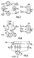
- FIG. 6 represents a part of a 15 k source separation subunit with direct structure intended to enter into the composition of a source separation device 15.
- the sub-unit comprises a plurality of multiplication cells 73 1 to 73 n , each receiving a mixed signal E 1 (t) to E n (t).
- Each of these multiplication cells multiplies the signal by the separation coefficient C k1 to C kn assigned to the input, with 1 ⁇ k ⁇ n.
- the outputs of all the multiplication cells 73 1 to 73 n are connected to a summator 125 k to add all the signals and deliver, on an output 72 k , the estimated primary signal X and k ( t ).
- the source separation device 15 contains as many partial sub-units 15 k as there are estimated signals X and k ( t ) to be determined, that is to say badges to be processed simultaneously.
- the adaptation of the separation coefficients C ki is carried out in adaptation means ADAPT 105.
- Figure 7 refers to a simple example dealing with only two mixing signals.
- the summer 112 receives, on the one hand, the signal E1 (t) and, on the other hand, the signal E2 (t) multiplied by a coefficient -b 12 in the multiplication cell 711.
- the summer 212 receives , on the one hand, the signal E2 (t) and, on the other hand, the output signal X and 1 ( t ) multiplied by a coefficient -b 21 in the multiplication cell 713.
- the estimated identification signals X and 1 ( t ) and X and 2 ( t ) are supplied respectively by the summers 112 and 212.
- a summator can therefore receive, on the one hand, directly one of the mixing signals and, on the other hand, both zero, one or more other mixing signals E (t) and zero, one or more estimated identification signals, the latter signals being weighted respectively by a separation coefficient. Cases with zero other mixing signals and with zero estimated identification signals are mutually exclusive.
- the adaptation of the coefficients b ki is carried out, as before, in adaptation means ADAPT 105.
- the summator 112 receives, on an input 76, the mixing signal Ei (t) to which the identification signal corresponds. estimated X andi ( t ) delivered by the output 78.
- the adder 112 also receives other mixing signals Ej (t) and / or estimated identification signals X andj ( t ) on other inputs 79 1 to 79 n-1 , these other signals being weighted by separation coefficients in cells 80 1 to 80 n-1 .
- the adaptation of the coefficients b ki is carried out, as before, in adaptation means ADAPT 105.
- FIGS. 5, 6, 7, 8 have been shown with filter cells formed by multiplication cells each applying a single separation coefficient.
- the filter cell 211 (multiplication cell) of FIG. 5 must be replaced by the adaptive filter cell shown in FIG. 9.
- This adaptive filter cell comprises a battery of shift registers 90 1 to 90 p of which the outputs are connected to multiplication means 92 0 to 92 p whose role is to multiply the signal presented on their input each by a weighting coefficient.
- the outputs of all the multiplication means 92 0 to 92 p are added in a summation means 95 which delivers a filtered version ⁇ I (t)> of the signal I (t) placed at the input.
Landscapes
- Engineering & Computer Science (AREA)
- Physics & Mathematics (AREA)
- Toxicology (AREA)
- Artificial Intelligence (AREA)
- Computer Vision & Pattern Recognition (AREA)
- General Physics & Mathematics (AREA)
- Theoretical Computer Science (AREA)
- Health & Medical Sciences (AREA)
- Computer Networks & Wireless Communication (AREA)
- Electromagnetism (AREA)
- General Health & Medical Sciences (AREA)
- Signal Processing (AREA)
- Mobile Radio Communication Systems (AREA)
- Data Exchanges In Wide-Area Networks (AREA)
Description
- une entrée reliée respectivement à un signal de mélange,
- une sortie pour délivrer soit le signal d'identification estimé d'un des porteurs de données, soit un signal d'estimation dépendant du signal d'identification,
- et n-1 entrées reliées chacune respectivement à la sortie d'un des n-1 autres sommateurs à travers respectivement n-1 moyens de filtrage appliquant respectivement au moins un coefficient de filtrage,
- n entrées reliées chacune respectivement à un des n signaux de mélange à travers respectivement n moyens de filtrage appliquant respectivement au moins un coefficient de filtrage,
- et une sortie pour délivrer soit le signal d'identification estimé d'un des porteurs de données, soit un signal d'estimation dépendant du signal d'identification,
- une entrée reliée respectivement à un signal de mélange,
- une sortie pour délivrer soit le signal d'identification estimé d'un des porteurs de données, soit un signal d'estimation dépendant du signal d'identification,
- et n-1 entrées reliées, pour une part, respectivement à la sortie d'une partie des n-1 autres sommateurs, et pour une autre part, respectivement à un des autres signaux de mélange, à travers respectivement n-1 moyens de filtrage appliquant respectivement au moins un coefficient de filtrage,


Claims (8)
- Système d'échange de données comprenant une station de base(1) et au moins un porteur de données (21, 22) couplés l'un à l'autre à travers des liaisons sans fil pour échanger des données, la station comprenant des moyens d'émission (10,11) et des moyens de réception (18) pour respectivement interroger au moins un porteur de données (21, 22) et pour recevoir, en réponse, un signal d'identification émis par le porteur de données interrogé, le porteur de données comportant des moyens d'émission (21b)/réception (21a), système dans lequel, pour établir simultanément plusieurs liaisons sans fil entre la station de base (1) et plusieurs porteurs de données (21, 22), les moyens de réception (18) de la station comportent un dispositif de séparation de sources (15) pour traiter des signaux de mélanges (E1(t), E2(t)) dépendant de mélanges des signaux d'identification émis par les porteurs de données, caractérisé en ce que ledit dispositif de séparation de sources (15) comprend des moyens de filtrage destinés à filtrer lesdits signaux de mélange à l'aide de coefficients de filtrage, des moyens de sommation des signaux de mélange filtrés, des moyens d'adaptation (105) desdits coefficients de filtrage, les moyens de réception (18) comportant plusieurs unités de démodulation (121, 122) placées soit en sortie soit en entrée des moyens de séparation de sources (15), les moyens de réception délivrant des signaux d'identification estimés (X and 1(t),X and 2( t ))pour lesdits porteurs de données à connecter simultanément.
- Système selon la revendication 1 caractérisé en ce que, pour identifier simultanément n porteurs de données, le dispositif de séparation de sources (15) comprend n sommateurs (112, 212, 312) récursivement connectés, chaque sommateur ayant:une entrée (110) reliée respectivement à un signal de mélange (E1(t)),une sortie (115) pour délivrer soit le signal d'identification estimé (X ^ / 1(t)) d'un des porteurs de données, soit un signal d'estimation dépendant du signal d'identification,et n-1 entrées reliées chacune respectivement à la sortie d'un des n-1 autres sommateurs (212, 312) à travers respectivement n-1 moyens de filtrage appliquant respectivement au moins un coefficient de filtrage (d12, d13).
- Système selon la revendication 1 caractérisé en ce que, pour identifier simultanément n porteurs de données, le dispositif de séparation de sources (15) comprend n sommateurs (125k) non récursivement connectés, chaque sommateur ayant:n entrées (701-70n) reliées chacune respectivement à un des n signaux de mélange (E1(t)-En(t)) à travers respectivement n moyens de filtrage appliquant respectivement au moins un coefficient de filtrage (Ck1-Ckn),et une sortie (72k) pour délivrer soit le signal d'identification estimé (X ^ / k(t)) d'un des porteurs de données, soit un signal d'estimation dépendant du signal d'identification.
- Système selon la revendication 1 caractérisé en ce que, pour identifier simultanément n porteurs de données, le dispositif de séparation de sources (15) comprend n sommateurs (112, 212), chaque sommateur ayant:une entrée (76) reliée respectivement à un signal de mélange (Ei(t))une sortie (78) pour délivrer soit le signal d'identification estimé (X and i(t)) d'un des porteurs de données, soit un signal d'estimation dépendant du signal d'identification,et n-1 entrées reliées (791-79n-1), pour une part, respectivement à la sortie d'une partie des n-1 autres sommateurs (X andj (t)), et pour une autre part, respectivement à un des autres signaux de mélange (Ej(t)), à travers respectivement n-1 moyens de filtrage (801-80n-1) appliquant respectivement au moins un coefficient de filtrage.
- Station de base destinée à être couplée par des liaisons sans fil à au moins un porteur de données, la station comprenant des moyens d'émission (10,11) et des moyens de réception (18) pour respectivement interroger le porteur de données et pour recevoir en réponse un signal d'identification émis par le porteur de données interrogé, station dans laquelle, pour établir simultanément plusieurs liaisons sans fil avec plusieurs porteurs de données (2 1 , 2 2 ), les moyens de réception (18) comportent un dispositif de séparation de sources (15) pour traiter des signaux de mélanges dépendant de mélanges des signaux d'identification émis par les porteurs de données, caractérisé en ce que ledit dispositif de séparation de sources comprend des moyens de filtrage destinés à filtrer lesdits signaux de mélange à l'aide de coefficients de filtrage, des moyens de sommation des signaux de mélange filtrés, des moyens d'adaptation (105) desdits coefficients de filtrage, les moyens de réception (18) comportant plusieurs unités de démodulation (121, 122) placées soit en sortie soit en entrée des moyens de séparation de sources, les moyens de réception délivrant des signaux d'identification estimés pour lesdits porteurs de données à connecter simultanément.
- Station de base selon la revendication 5 caractérisée en ce que, pour identifier simultanément n porteurs de données, le dispositif de séparation de sources (15) comprend n sommateurs récursivement connectés (112, 212, 312), chaque sommateur ayant:une entrée (110) reliée respectivement à un signal de mélange (E1(t)),une sortie (115) pour délivrer soit le signal d'identification estimé ((X and 1(t)) d'un des porteurs de données, soit un signal d'estimation dépendant du signal d'identification,et n-1 entrées (111, 113) reliées chacune respectivement à la sortie d'un des n-1 autres sommateurs (212, 312) à travers respectivement n-1 moyens de filtrage appliquant respectivement au moins un coefficient de filtrage (d12, d13).
- Station de base selon la revendication 5 caractérisée en ce que, pour identifier simultanément n porteurs de données, le dispositif de séparation de sources (15k) comprend n sommateurs (125k), chaque sommateur ayant:n entrées (731-73n) reliées chacune respectivement à un des n signaux de mélange (E1(t)-En(t)) à travers respectivement n moyens de filtrage appliquant respectivement au moins un coefficient de filtrage (Ck1-Ckn),et une sortie (72k) pour délivrer soit le signal d'identification estimé ((X andk (t)) d'un des porteurs de données, soit un signal d'estimation dépendant du signal d'identification.
- Station de base selon la revendication 5 caractérisée en ce que, pour identifier simultanément n porteurs de données, le dispositif de séparation de sources comprend n sommateurs non récursivement connectés, chaque sommateur ayant:une entrée (76) reliée respectivement à un signal de mélange (Ei(t)),une sortie (78) pour délivrer soit le signal d'identification estimé (X andi (t)) d'un des porteurs de données, soit un signal d'estimation dépendant du signal d'identification,et n-1 entrées (791-79n-1) reliées, pour une part, respectivement à la sortie (X andj (t)) d'une partie des n-1 autres sommateurs, et pour une autre part, respectivement à un des autres signaux de mélange (Ej(t)), à travers respectivement n-1 moyens de filtrage (801-80n-1) appliquant respectivement au moins un coefficient de filtrage.
Applications Claiming Priority (2)
| Application Number | Priority Date | Filing Date | Title |
|---|---|---|---|
| FR9510444 | 1995-09-06 | ||
| FR9510444A FR2738369A1 (fr) | 1995-09-06 | 1995-09-06 | Systeme d'echange de donnees comportant une pluralite de porteurs de donnees. |
Publications (2)
| Publication Number | Publication Date |
|---|---|
| EP0762310A1 EP0762310A1 (fr) | 1997-03-12 |
| EP0762310B1 true EP0762310B1 (fr) | 2004-11-03 |
Family
ID=9482312
Family Applications (1)
| Application Number | Title | Priority Date | Filing Date |
|---|---|---|---|
| EP96202413A Expired - Lifetime EP0762310B1 (fr) | 1995-09-06 | 1996-08-30 | Système d'échange de données comportant une pluralité de porteurs de données |
Country Status (7)
| Country | Link |
|---|---|
| US (1) | US5956654A (fr) |
| EP (1) | EP0762310B1 (fr) |
| JP (1) | JP3916699B2 (fr) |
| KR (1) | KR100397685B1 (fr) |
| CN (1) | CN1092892C (fr) |
| DE (1) | DE69633763T2 (fr) |
| FR (1) | FR2738369A1 (fr) |
Families Citing this family (6)
| Publication number | Priority date | Publication date | Assignee | Title |
|---|---|---|---|---|
| US6617962B1 (en) * | 2000-01-06 | 2003-09-09 | Samsys Technologies Inc. | System for multi-standard RFID tags |
| AU2001283101A1 (en) * | 2000-08-14 | 2002-02-25 | Adbeep. Com, Llc | Method and apparatus for displaying advertising indicia on wireless device |
| NZ526638A (en) * | 2000-12-22 | 2004-11-26 | Gallagher Group Ltd | Improved identification reader for decoding signals which have different modulation schemes |
| SE0103611D0 (sv) * | 2001-10-31 | 2001-10-31 | Pergo Ab | Surface covering unit |
| US20050099267A1 (en) * | 2002-03-13 | 2005-05-12 | Franz Amtmann | Communication station for communication with transponders and further communication stations with the aid of different transmission parameters |
| KR100769880B1 (ko) | 2006-04-27 | 2007-10-24 | 연세대학교 산학협력단 | Rfid 리더에서의 주파수 채널 탐색 장치 |
Family Cites Families (6)
| Publication number | Priority date | Publication date | Assignee | Title |
|---|---|---|---|---|
| GB8408538D0 (en) * | 1984-04-03 | 1984-05-16 | Senelco Ltd | Transmitter-responder systems |
| NL8901659A (nl) * | 1989-06-30 | 1991-01-16 | Nedap Nv | Multipassysteem. |
| US5500650A (en) * | 1992-12-15 | 1996-03-19 | Micron Technology, Inc. | Data communication method using identification protocol |
| CA2103288C (fr) * | 1992-11-18 | 2004-08-17 | Michael John Camille Marsh | Detection d'une multiplicite d'articles |
| US5349355A (en) * | 1993-01-21 | 1994-09-20 | The United States Of America As Represented By The Secretary Of The Navy | Credential tracking system |
| US5594447A (en) * | 1995-01-11 | 1997-01-14 | Mitsubishi Denki Kabushiki Kaisha | Moving target identifying system in a base station radar unit for specifying information about moving targets carrying a mobile station radar unit |
-
1995
- 1995-09-06 FR FR9510444A patent/FR2738369A1/fr not_active Withdrawn
-
1996
- 1996-08-30 DE DE69633763T patent/DE69633763T2/de not_active Expired - Fee Related
- 1996-08-30 EP EP96202413A patent/EP0762310B1/fr not_active Expired - Lifetime
- 1996-09-06 KR KR1019960038576A patent/KR100397685B1/ko not_active Expired - Fee Related
- 1996-09-06 CN CN96122459A patent/CN1092892C/zh not_active Expired - Fee Related
- 1996-09-06 JP JP23667396A patent/JP3916699B2/ja not_active Expired - Fee Related
- 1996-09-06 US US08/709,499 patent/US5956654A/en not_active Expired - Fee Related
Also Published As
| Publication number | Publication date |
|---|---|
| DE69633763T2 (de) | 2005-10-27 |
| US5956654A (en) | 1999-09-21 |
| KR100397685B1 (ko) | 2003-11-20 |
| FR2738369A1 (fr) | 1997-03-07 |
| DE69633763D1 (de) | 2004-12-09 |
| KR970019197A (ko) | 1997-04-30 |
| CN1092892C (zh) | 2002-10-16 |
| EP0762310A1 (fr) | 1997-03-12 |
| CN1160319A (zh) | 1997-09-24 |
| JPH09191320A (ja) | 1997-07-22 |
| JP3916699B2 (ja) | 2007-05-16 |
Similar Documents
| Publication | Publication Date | Title |
|---|---|---|
| EP2517141B1 (fr) | Carte a puce multi-applicatifs avec validation biometrique | |
| FR2981026A1 (fr) | Systeme de controle a distance, et procede pour verrouiller et/ou pour deverrouiller automatiquement au moins un ouvrant d'un vehicule automobile et/ou pour demarrer un moteur d'un vehicule automobile a l'aide d'un systeme de controle a distance | |
| EP2065857A2 (fr) | Carte à microprocesseur, téléphone comprenant une telle carte et procédé d'exécution d'une commande dans une telle carte | |
| EP3110190B1 (fr) | Procédé et dispositif de gestion d'applications sans contact | |
| EP0762310A1 (fr) | Système d'échange de données comportant une pluralité de porteurs de données | |
| FR2923632A1 (fr) | Carte a microprocesseur, telephone comprenant une telle carte et procede de traitement dans une telle carte. | |
| WO2015124535A1 (fr) | Procede et systeme de transaction electronique via un accessoire portable | |
| FR2803160A1 (fr) | Module d'interfacage pour un hote tel un decodeur, decodeur l'integrant et procede de traitement d'informations pour un hote | |
| FR2670594A1 (fr) | Carte portative de reception de messages personnels. | |
| WO1996008802A1 (fr) | Dispositif et procede de tele-controle d'un objet | |
| FR3011655A1 (fr) | Procede de communication par un lecteur de radio-etiquettes passives fonctionnant en mode de retrodiffusion | |
| EP1794896B1 (fr) | Dispositif sans contact de protection de la vie privee | |
| WO2019186041A1 (fr) | Procédé et dispositif d'authentification d'un utilisateur | |
| EP1459265B1 (fr) | Systeme et procede de detection du passage d'un individu ou d'un objet par une entree-sortie a un espace delimite | |
| CA2297797A1 (fr) | Objet portatif a communication sans contact suivant deux voies de communication, inductive et hertzienne | |
| EP3868029B1 (fr) | Gestion de transactions dans un dispositif nfc | |
| EP3813330B1 (fr) | Procédés et dispositifs d'appairage | |
| EP0337912A1 (fr) | Carte de détection et d'identification du type radar permettant un dialogue interactif | |
| EP3900228B1 (fr) | Procédé et dispositif de reconnaissance d'un utilisateur | |
| WO2005124656A1 (fr) | Procede et systeme de communication haut debit a contacts electriques | |
| EP4395187A1 (fr) | Protection d'une transaction | |
| EP3177998B1 (fr) | Procédé de consultation de l'état d'une ressource d'un appareil électronique, entité électronique associée et appareil électronique équipé d'une telle entité électronique | |
| FR2834811A1 (fr) | Procede d'anti-collision d'elements a identifier par un ordinateur hote | |
| FR2757335A1 (fr) | Procede et appareil electrique pour l'echange de donnees, et carte a puce pour la mise en oeuvre du procede | |
| WO2014001677A1 (fr) | Systeme de transmission securisee de donnees numeriques |
Legal Events
| Date | Code | Title | Description |
|---|---|---|---|
| PUAI | Public reference made under article 153(3) epc to a published international application that has entered the european phase |
Free format text: ORIGINAL CODE: 0009012 |
|
| AK | Designated contracting states |
Kind code of ref document: A1 Designated state(s): DE FR GB IT |
|
| 17P | Request for examination filed |
Effective date: 19970912 |
|
| RAP1 | Party data changed (applicant data changed or rights of an application transferred) |
Owner name: KONINKLIJKE PHILIPS ELECTRONICS N.V. |
|
| 17Q | First examination report despatched |
Effective date: 20030312 |
|
| GRAP | Despatch of communication of intention to grant a patent |
Free format text: ORIGINAL CODE: EPIDOSNIGR1 |
|
| GRAS | Grant fee paid |
Free format text: ORIGINAL CODE: EPIDOSNIGR3 |
|
| GRAA | (expected) grant |
Free format text: ORIGINAL CODE: 0009210 |
|
| AK | Designated contracting states |
Kind code of ref document: B1 Designated state(s): DE FR GB IT |
|
| REG | Reference to a national code |
Ref country code: GB Ref legal event code: FG4D Free format text: NOT ENGLISH |
|
| REF | Corresponds to: |
Ref document number: 69633763 Country of ref document: DE Date of ref document: 20041209 Kind code of ref document: P |
|
| GBT | Gb: translation of ep patent filed (gb section 77(6)(a)/1977) | ||
| REG | Reference to a national code |
Ref country code: GB Ref legal event code: 746 Effective date: 20050105 |
|
| PLBE | No opposition filed within time limit |
Free format text: ORIGINAL CODE: 0009261 |
|
| STAA | Information on the status of an ep patent application or granted ep patent |
Free format text: STATUS: NO OPPOSITION FILED WITHIN TIME LIMIT |
|
| 26N | No opposition filed |
Effective date: 20050804 |
|
| PGFP | Annual fee paid to national office [announced via postgrant information from national office to epo] |
Ref country code: GB Payment date: 20070925 Year of fee payment: 12 |
|
| PGFP | Annual fee paid to national office [announced via postgrant information from national office to epo] |
Ref country code: IT Payment date: 20070829 Year of fee payment: 12 Ref country code: DE Payment date: 20071015 Year of fee payment: 12 |
|
| PGFP | Annual fee paid to national office [announced via postgrant information from national office to epo] |
Ref country code: FR Payment date: 20070807 Year of fee payment: 12 |
|
| GBPC | Gb: european patent ceased through non-payment of renewal fee |
Effective date: 20080830 |
|
| REG | Reference to a national code |
Ref country code: FR Ref legal event code: ST Effective date: 20090430 |
|
| PG25 | Lapsed in a contracting state [announced via postgrant information from national office to epo] |
Ref country code: IT Free format text: LAPSE BECAUSE OF NON-PAYMENT OF DUE FEES Effective date: 20080830 Ref country code: FR Free format text: LAPSE BECAUSE OF NON-PAYMENT OF DUE FEES Effective date: 20080901 Ref country code: DE Free format text: LAPSE BECAUSE OF NON-PAYMENT OF DUE FEES Effective date: 20090303 |
|
| PG25 | Lapsed in a contracting state [announced via postgrant information from national office to epo] |
Ref country code: GB Free format text: LAPSE BECAUSE OF NON-PAYMENT OF DUE FEES Effective date: 20080830 |