EP0762369B1 - Profil für eine Anzeigevorrichtung und eine Anzeigevorrichtung, die aus solchen Profilen zusammengestellt ist - Google Patents
Profil für eine Anzeigevorrichtung und eine Anzeigevorrichtung, die aus solchen Profilen zusammengestellt ist Download PDFInfo
- Publication number
- EP0762369B1 EP0762369B1 EP96401558A EP96401558A EP0762369B1 EP 0762369 B1 EP0762369 B1 EP 0762369B1 EP 96401558 A EP96401558 A EP 96401558A EP 96401558 A EP96401558 A EP 96401558A EP 0762369 B1 EP0762369 B1 EP 0762369B1
- Authority
- EP
- European Patent Office
- Prior art keywords
- plane
- face
- faces
- section
- display device
- Prior art date
- Legal status (The legal status is an assumption and is not a legal conclusion. Google has not performed a legal analysis and makes no representation as to the accuracy of the status listed.)
- Expired - Lifetime
Links
- 230000001154 acute effect Effects 0.000 claims description 5
- 238000005034 decoration Methods 0.000 claims description 2
- 238000005452 bending Methods 0.000 description 4
- KWGRBVOPPLSCSI-WPRPVWTQSA-N (-)-ephedrine Chemical compound CN[C@@H](C)[C@H](O)C1=CC=CC=C1 KWGRBVOPPLSCSI-WPRPVWTQSA-N 0.000 description 1
- 238000004519 manufacturing process Methods 0.000 description 1
- 230000000284 resting effect Effects 0.000 description 1
- 125000006850 spacer group Chemical group 0.000 description 1
Images


Classifications
-
- G—PHYSICS
- G09—EDUCATION; CRYPTOGRAPHY; DISPLAY; ADVERTISING; SEALS
- G09F—DISPLAYING; ADVERTISING; SIGNS; LABELS OR NAME-PLATES; SEALS
- G09F15/00—Boards, hoardings, pillars, or like structures for notices, placards, posters, or the like
- G09F15/0006—Boards, hoardings, pillars, or like structures for notices, placards, posters, or the like planar structures comprising one or more panels
- G09F15/0012—Boards, hoardings, pillars, or like structures for notices, placards, posters, or the like planar structures comprising one or more panels frames therefor
Definitions
- the present invention relates to a profile for the production at least two opposite parallel sides of a device display, such as a panel or board, intended for present a poster with indications, information, advertising or the like and / or used to decoration. It also relates to such a device display produced at least partially using said display streamlined.
- the object of the present invention is to enable the realization display devices in which the presentation of the poster can be both flat and curved and thanks to which one or more faces of presentation of said poster.
- a device display having at least a couple of two sides opposite parallels each consisting of a profile, said sections profiles of the couple being made integral with one another so that the first and third plane faces of one profiles are located opposite respectively first and third plane faces of the other of said profiles of the couple and that said first planar faces of the two profiles are coplanar.
- each of the four flat faces of a profile can be formed by a facet of it, internal or external.
- At least one of the four flat faces of the profile can have or be formed by the edges of a groove in a rectangular dovetail.
- a rectangular dovetail groove whose ledges constitute said flat face or are part of the latter.
- the section of said profile has a shape general triangular. As we will see below, it can be advantageous that the outside angle of said section is equal to 30 degrees.
- the third and fourth flat faces of the profile form two consecutive walls of a bent section groove.
- the profile may include a third and / or a fourth additional flat face, for example respectively parallel to said third or fourth planar face.
- this poster can spontaneously take a parallel position at the first faces of two profiles forming a couple of display device.
- the lateral edge a poster is applied and / or attached to the fourth side plane or the fourth additional plane face of a streamlined, said poster may spontaneously take a curved shape towards the outside of the display device.
- said poster is supported by two of its opposite edges by said third flat faces of said sections constituting the two opposite parallel sides of said display device and said poster is parallel to said first faces profiles planes.
- the poster is supported by two of its edges opposite by said fourth flat face of sections constituting the two opposite parallel sides of the display device and the poster is curved relative to said first flat faces of the profiles, with its concavity directed towards said planar faces.
- the poster can be made of a sheet of a relatively rigid material, but easily bendable.
- a relatively rigid support is provided and bendable against which the said poster is applied and which is used to secure it to the profiles.
- said profiles can form both horizontal sides as the vertical sides of the device display according to the invention, except possibly in the case where the poster is curved.
- the two profiles of a couple of the display device form the vertical sides of it, because then said profiles can be part and / or constitute the base of this display device.
- this includes another couple of two opposite parallel sections identical to the first couple mentioned above and the two couples are joined to each other by said first faces of profiles that constitute them.
- a display device which can have two posters directed in opposite directions.
- said device in the case where the triangular section of the two profiles has an angle at the top of 30 degrees, said device includes two other pairs of two profiles opposite parallels, identical to the first couple mentioned and the three couples are two by two joined by the second faces of the sections which constitute them.
- a display device capable of presenting three posters, whose planes form an equilateral triangle.
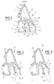
- Figure 1 shows the section of a first embodiment of the profile according to the present invention.
- Figures 2 and 3 illustrate the arrangement of the side edge of a poster, respectively, to be parallel to the profile reference face ( Figure 2) or be curved by compared to the latter ( Figure 3).
- Figure 4 illustrates a sectional display device consisting of two profiles similar to that of the figure 1, the poster being parallel to the reference faces of the two profiles constituting the display device.
- FIG. 5 illustrates an embodiment of the device display in which the poster is displayed curved.
- Figure 6 shows, also in section, an embodiment display device in accordance with this invention, consisting of four sections conforming to the figure 1.
- Figure 7 illustrates in section another alternative embodiment display device in accordance with this invention, consisting of six sections according to the figure 1.
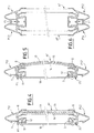
- FIG. 8 shows, in section, an alternative embodiment of the profile according to the present invention.
- Figure 9 illustrates the attachment of the side edge of a displays, in case this must be parallel to the reference face of said profile.
- Figures 10 and 11 illustrate two variants of the attachment from the side edge of a poster in case it must be curved outwards.
- Figures 12, 13 and 14 illustrate, in section, three modes of the display device according to the present invention, constituted respectively by two, four and six sections illustrated in figure 8.
- the second and fourth oblique faces F2 and F4 are each directed towards the other and converge one towards each other, by making an angle C, for example equal to 30 degrees.
- the P1 profile has another bent tab 6, external, the parts of which 6a and 6b are respectively separated and substantially parallel to parts 5a and 5b of the bent tab 5, of so that said tabs 5 and 6 delimit between them an angled groove G, the opening of which, delimited by the parts of tabs 5a and 6a, has a direction general parallel to the third face F3 and the bottom of which, delimited by the parts of tabs 5b and 6b, present a general direction parallel to the fourth face F4.
- the bent tab 6 is extended towards the face F2 by a fifth external flat face F5, for example parallel to said fourth face F4 and making an acute angle C, by example equal to 30 degrees, with the side F2, so that the section of profile P1 has a generally triangular shape.
- the edge b of the poster AF is engaged deep in the groove G so as to be applied and / or fixed against the fourth face F4 of the profile P1.
- the lateral part of the AF attachment is inclined towards the outside with respect to the reference face F1, so that the AF poster bulges naturally when its lateral edge opposite the edge b is brought back towards the F1 face plan.
- Figures 4 and 5 show the two modes of presentation of the AF poster, respectively shown on the Figures 2 and 3, in the case of a display device consisting of a pair of two identical sections P1.1 and P1.2 to profile P1 in Figure 1.
- the two profiles P1.1 and P1.2 are arranged so that their grooves G are in look at each other and that their F1 reference faces are coplanar.
- the two sections P1.1 and P1.2 were made integral from each other by a spacer 10 resting on the F1 reference faces of the two profiles and fixed to them by screw and nut systems 11, 12, cooperating with the grooves 3.
- the poster AF is flat and parallel to the plane of the faces F1, in accordance with what is shown in figure 2.
- the AF poster is curved towards the exterior, its concavity being directed towards the plane of F1 reference faces of profiles P1.1 and P1.2, the edges of said poster cooperating with the fourth faces of these two profiles, as shown in Figure 3.
- the profile P1 further comprises a bent tab 9 carrying a third additional flat face F3 'and a fourth additional flat face F4 ', respectively parallel to said third flat face F3 or the fourth flat face F4, so that said tabs 5 and 9 define between them an additional angled groove G ', similar to the angled throat G.
- the groove G ′ can be used as the groove G, especially for fixing bending mandrel 14 (see below).
- the variant embodiment of the display device shown in Figure 6 has, in addition to the pair of profiles P1.1 and P1.2 mentioned above, another pair of profiles P1.3 and P1.4, also identical to profile P1 of Figure 1.
- FIG 7 there is shown in section a another variant of the display device according to the present invention having three faces of presentation at 60 degrees.
- This variant embodiment comprises three pairs of sections P1.1, P1.2; P1.3, P1.4 and P1.5, P1.6 respectively identical to each other and to P1 profile of Figure 1.
- Each couple is arranged to identical to profiles P1.1 and P1.2 in Figures 4 and 5 and the couples are two by two joined by the faces oblique F2 of their profiles.
- a rigid support 14 is provided which is applied said poster 13. In the case of a presentation curved, this support 14 is more bendable, so serve as a bending mandrel for poster 13.
- another transparent plate 15 covers poster 13 to protect it.
- FIGS. 9 and 10 there are shown provisions respectively similar to those of FIGS. 2 and 3, the lateral edge b of the poster AF being fixed respectively to said third and fourth faces F3 and F4 by means of screws and nuts 28 and 29. It is therefore easily understood that, by using the face F3 or the face F4 of the section P2 of FIG. 8, it is possible to obtain, for the AF poster, a flat presentation or a domed presentation respectively similar to those illustrated in Figures 4 and 5.
- FIG. 11 a variant of FIG. 10 has been illustrated, using the fourth additional face F4 '.
- the extreme lateral edge b of the poster AF is engaged in the groove g .
- FIGS. 12, 13 and 14 three modes of realization of the device according to the present invention, produced using pairs of profiles P2.1, P2.2; P2.3, P2.4 and P2.5, P2.6 identical to each other, as well as to the profile P2 and corresponding respectively to the embodiments Figures 4, 5, 6 and 7 relating to the profile P1.
Landscapes
- Physics & Mathematics (AREA)
- General Physics & Mathematics (AREA)
- Engineering & Computer Science (AREA)
- Theoretical Computer Science (AREA)
- Illuminated Signs And Luminous Advertising (AREA)
- Testing, Inspecting, Measuring Of Stereoscopic Televisions And Televisions (AREA)
- Devices For Indicating Variable Information By Combining Individual Elements (AREA)
- Measuring Pulse, Heart Rate, Blood Pressure Or Blood Flow (AREA)
- Tents Or Canopies (AREA)
- Preliminary Treatment Of Fibers (AREA)
Claims (20)
- Profilteil (P1, P2) für die Realisierung wenigstens zweier einander gegenüberliegender, paralleler Seiten einer Anzeigevorrichtung, wie eine Platte oder eine Tafel, die zur Präsentation einer Anzeigefläche (AF) bestimmt ist, welche Anzeigen, Informationen, Werbung oder Ähnliches trägt,
dadurch gekennzeichnet,daß sie im Schnitt umfaßt,eine erste ebene Bezugsfläche (F1),eine schräge zweite ebene Fläche (F2), die mit der ersten ebenen Bezugsfläche (F1) einen stumpfen Winkel (A) bildet,eine dritte ebene Fläche (F3), die von der ersten ebenen Bezugsfläche (F1) entfernt und zu dieser im wesentlichen parallel ist, undeine schräge vierte ebene Fläche (F4), die mit der dritten ebenen Fläche (F3) einen stumpfen Winkel (B) bildet,und daß die schrägen zweiten und vierten ebenen Flächen (F2, F4) miteinander einen spitzen Winkel (C) bilden. - Profilteil nach Anspruch 1, dadurch gekennzeichnet, daß wenigstens eine seiner vier ebenen Flächen (F1, F2, F3, F4) die Ränder (1, 2 - 23, 24) einer schwalbenschwanzförmigen Nut mit rechteckiger Form (3 - 25) beinhaltet.
- Profilteil nach einem der Ansprüche 1 oder 2, dadurch gekennzeichnet, daß die dritten und vierten ebenen Flächen (F3, F4) äußere Schrägflächen des Profilteils bilden.
- Profilteil nach Anspruch 3, dadurch gekennzeichnet, daß die zweiten und vierten Flächen (F2, F4) miteinander einen Winkel von 30 Grad bilden.
- Profilteil nach einem der Ansprüche 1 oder 2, dadurch gekennzeichnet, daß die dritten und vierten ebenen Flächen (F3, F4) innere Schrägflächen des Profilteils bilden.
- Profilteil nach Anspruch 5, dadurch gekennzeichnet, daß es eine äußere Schrägfläche (F5) aufweist, die in bezug auf die dritten und vierten inneren ebenen Flächen (F3, F4) außen liegt und mit der zweiten ebenen Fläche (F2) einen spitzen Winkel (C) bildet.
- Profilteil nach Anspruch 6, dadurch gekennzeichnet, daß die äußere Schrägfläche (F5) zur vierten inneren ebenen Fläche (F4) parallel ist.
- Profilteil nach einem der Ansprüche 5 oder 6, dadurch gekennzeichnet, daß die äußere Schrägfläche (F5) und die zweite ebene Fläche (F2) miteinander einen Winkel von 30 Grad bilden.
- Profilteil nach einem der Ansprüche 5 bis 8, dadurch gekennzeichnet, daß die dritten und vierten ebenen Flächen zwei benachbarte Wände einer Nut mit knieförmigem Schnitt (G) bilden.
- Profilteil nach einem der Ansprüche 1 bis 9, dadurch gekennzeichnet, daß es eine zusätzliche dritte ebene Fläche (F3') aufweist, die von der ersten ebenen Bezugsfläche (F1) entfernt und zu dieser im wesentlichen parallel ist.
- Profilteil nach Anspruch 10, dadurch gekennzeichnet, daß die dritte zusätzliche ebene Fläche (F3') zur dritten ebenen Fläche (F3) parallel ist.
- Profilteil nach einem der Ansprüche 1 bis 11, dadurch gekennzeichnet, daß es eine zusätzliche vierte ebene Fläche (F4') aufweist, die mit der dritten ebenen Fläche einen stumpfen Winkel bildet.
- Profilteil nach Anspruch 12, dadurch gekennzeichnet, daß die zusätzliche vierte ebene Fläche (F4') zur vierten ebenen Fläche (F4) parallel ist.
- Anzeigevorrichtung, wie eine Platte oder eine Tafel, die zur Präsentation einer Anzeigefläche bestimmt ist, welche Anzeigen, Informationen, Werbung oder Ähnliches trägt, oder als Dekoration dienen soll, wobei die Anzeigevorrichtung wenigstens ein Paar von zwei einander gegenüberliegenden, parallelen Seiten aufweist, die jeweils aus einem Profilteil bestehen,
dadurch gekennzeichnet,daß jedes der Profilteile (P1.1, P1.2 - P2.1, P2.2), die die Seiten der Anzeigevorrichtung bilden, im Schnitt aufweist,eine erste ebene Bezugsfläche (F1),eine schräge zweite ebene Fläche (F2), die mit der ersten ebenen Bezugsfläche (F1) einen stumpfen Winkel (A) bildet,eine dritte ebene Fläche (F3), die von der ersten ebenen Bezugsfläche (F1) entfernt und zu dieser im wesentlichen parallel ist, undeine schräge vierte ebene Fläche (F4), die mit der dritten ebenen Fläche (F3) einen stumpfen Winkel (B) bildet, wobei die schrägen zweiten und vierten ebenen Flächen miteinander einen spitzen Winkel (C) bilden,und daß die Profilteile miteinander fest verbunden werden, so daß die ersten und dritten ebenen Flächen eines der Profilteile sich den ersten bzw. dritten ebenen Flächen des anderen Profilteils gegenüber befinden, und daß die ersten ebenen Flächen der beiden Profilteile koplanar sind. - Anzeigevorrichtung nach Anspruch 14, dadurch gekennzeichnet, daß die Anzeigefläche (AF) durch zwei ihrer entgegengesetzten Ränder (b) von den dritten ebenen Flächen (F3) der Profilteile getragen wird, die die beiden einander gegenüberliegenden, parallelen Seiten der Anzeigevorrichtung bilden, und daß die Anzeigefläche zu den ersten ebenen Flächen (F1) der Profilteile parallel ist.
- Anzeigevorrichtung nach Anspruch 14, dadurch gekennzeichnet, daß die Anzeigefläche durch zwei ihrer entgegengesetzten Ränder (b) von den vierten ebenen Flächen (F4) der Profilteile getragen wird, die die beiden einander gegenüberliegenden, parallelen Seiten der Anzeigevorrichtung bilden, und daß die Anzeigefläche in bezug auf die ersten ebenen Flächen der Profilteile gewölbt ist, wobei ihre Konkavität zu den ersten ebenen Flächen (F1) zeigt.
- Anzeigevorrichtung nach einem der Ansprüche 14 bis 16 für die Präsentation einer dünnen Anzeigefläche, dadurch gekennzeichnet, daß sie einen Träger (14) aufweist, an dem die dünne Anzeigefläche angebracht ist, und der zur Verbindung der Anzeigefläche mit den Profilteilen dient.
- Anzeigevorrichtung nach einem der Ansprüche 14 bis 17, dadurch gekennzeichnet, daß die Profilteile (P1.1, P1.2; P2.1, P2.2) vertikale Seiten der Vorrichtung bilden.
- Anzeigevorrichtung nach einem der Ansprüche 14 bis 18, dadurch gekennzeichnet, daß sie ein weiteres Paar (P1.3, P1.4; P2.3, P2.4) von zwei einander gegenüberliegenden, parallelen Seiten aufweist, die zum ersten Paar identisch sind, und daß die beiden Paare durch die ersten Flächen (F1) der Profilteile, die sie bilden, aneinandergefügt sind.
- Anzeigevorrichtung nach einem der Ansprüche 14 bis 18, dadurch gekennzeichnet, daß sie zwei weitere Paare (P1.3, P1.4; P1.5, P1.6 - P2.3, P2.4; P2.5, P2.6) von zwei einander gegenüberliegenden, parallelen Seiten aufweist, die zum ersten Paar identisch sind, und daß jedes der Profilteile einen dreieckigen Schnitt aufweist, dessen Winkel auf der Seite der zweiten und vierten ebenen Flächen gleich 30 Grad beträgt, und daß die drei Paare paarweise durch die zweiten Flächen (F2) der Profilteile, die sie bilden, zusammengefügt sind.
Applications Claiming Priority (3)
| Application Number | Priority Date | Filing Date | Title |
|---|---|---|---|
| FR9510124 | 1995-08-28 | ||
| FR9510214A FR2738374B1 (fr) | 1995-08-30 | 1995-08-30 | Profile pour dispositif d'affichage et dispositif d'affichage realise avec ledit profile |
| FR9510214 | 1995-08-30 |
Publications (2)
| Publication Number | Publication Date |
|---|---|
| EP0762369A1 EP0762369A1 (de) | 1997-03-12 |
| EP0762369B1 true EP0762369B1 (de) | 1999-04-07 |
Family
ID=9482165
Family Applications (1)
| Application Number | Title | Priority Date | Filing Date |
|---|---|---|---|
| EP96401558A Expired - Lifetime EP0762369B1 (de) | 1995-08-30 | 1996-07-15 | Profil für eine Anzeigevorrichtung und eine Anzeigevorrichtung, die aus solchen Profilen zusammengestellt ist |
Country Status (5)
| Country | Link |
|---|---|
| EP (1) | EP0762369B1 (de) |
| AT (1) | ATE178734T1 (de) |
| DE (1) | DE69601992T2 (de) |
| ES (1) | ES2130765T3 (de) |
| FR (1) | FR2738374B1 (de) |
Families Citing this family (5)
| Publication number | Priority date | Publication date | Assignee | Title |
|---|---|---|---|---|
| DE29815265U1 (de) * | 1998-08-19 | 1999-09-23 | ABB Daimler-Benz Transportation (Technology) GmbH, 13627 Berlin | Einbaukonstruktion für ein Anzeigegerät |
| JP2004234780A (ja) * | 2003-01-31 | 2004-08-19 | Toshiba Corp | 磁気記録再生装置及び磁気ヘッド |
| DE10360595A1 (de) * | 2003-12-19 | 2005-07-28 | Jakob Maul Gmbh | Glasboard |
| FR2961936A1 (fr) * | 2010-06-28 | 2011-12-30 | Sud L A Ser | Profile multifonction pour un dispositif de signaletique et dispositif de signaletique realise avec le profile |
| CN105761640B (zh) * | 2016-05-16 | 2018-08-31 | 杭州邦美展览器材有限公司 | 一种背光绷布拉网展架 |
Family Cites Families (4)
| Publication number | Priority date | Publication date | Assignee | Title |
|---|---|---|---|---|
| DE2140232A1 (de) * | 1971-08-11 | 1973-03-01 | Rido Busse | Bilderrahmen |
| EP0277796A3 (de) * | 1987-01-31 | 1990-09-05 | Signaid Limited | Anzeige |
| DE4040124C1 (en) * | 1990-12-15 | 1992-02-20 | Metallbauwerk Tegtmeier Gmbh & Co Kg, 4972 Loehne, De | Fixing appts. for placards - incorporates frame with gap accommodating placard edge |
| US5377463A (en) * | 1991-10-25 | 1995-01-03 | Howe Ian T | Panel mounting |
-
1995
- 1995-08-30 FR FR9510214A patent/FR2738374B1/fr not_active Expired - Fee Related
-
1996
- 1996-07-15 EP EP96401558A patent/EP0762369B1/de not_active Expired - Lifetime
- 1996-07-15 ES ES96401558T patent/ES2130765T3/es not_active Expired - Lifetime
- 1996-07-15 DE DE69601992T patent/DE69601992T2/de not_active Expired - Fee Related
- 1996-07-15 AT AT96401558T patent/ATE178734T1/de not_active IP Right Cessation
Also Published As
| Publication number | Publication date |
|---|---|
| FR2738374B1 (fr) | 1997-11-14 |
| ATE178734T1 (de) | 1999-04-15 |
| EP0762369A1 (de) | 1997-03-12 |
| FR2738374A1 (fr) | 1997-03-07 |
| DE69601992T2 (de) | 2000-03-30 |
| ES2130765T3 (es) | 1999-07-01 |
| DE69601992D1 (de) | 1999-05-12 |
Similar Documents
| Publication | Publication Date | Title |
|---|---|---|
| USD419864S (en) | Combined bottle and cap | |
| USD1032249S1 (en) | Combined digital signage with display stand | |
| EP0762369B1 (de) | Profil für eine Anzeigevorrichtung und eine Anzeigevorrichtung, die aus solchen Profilen zusammengestellt ist | |
| FR3121087A1 (fr) | Dispositif d’affichage | |
| USD410861S (en) | Safety sign | |
| EP0801912A2 (de) | Modulares Schaugestell | |
| WO1996032707A1 (fr) | Caisson lumineux | |
| FR2499839A1 (fr) | Perfectionnements aux cadres pour gravures, photographies ou analogues | |
| USD1119651S1 (en) | Road information display sign | |
| USD1120790S1 (en) | Road information display sign | |
| FR2773969A3 (fr) | Support de presentation comportant un cadre et un fond | |
| EP1557502B1 (de) | Umkehrbares Solidarisierungselement, Bretter und Ordnen, die solche Elemente verwirklichen | |
| EP1562165B1 (de) | Anzeigevorrichtung zur Identifizierung oder zur Bestimmung von Gebauden | |
| FR2673086A1 (fr) | Renfort metallique pour tablette de rayonnage et tablette aussi renforcee. | |
| USD433454S (en) | Advertising sign for vehicles | |
| EP1360679A1 (de) | Werbetafel aus einer vielzahl von abnehmbaren bildteilen, die auf seitenflächen angeordnet sind | |
| FR2683653A1 (fr) | Dispositif d'affichage et de visualisation. | |
| WO1996020799A1 (fr) | Procede de fabrication de pieces plates, et pieces plates formees par sa mise en ×uvre | |
| JP3500186B2 (ja) | 枠体構造 | |
| FR2931577A1 (fr) | Dispositif d'affichage pour feuille ou document | |
| FR2469160A1 (fr) | Dispositif de support pour medaille ou plaque commemorative | |
| FR2761509A1 (fr) | Structure de borne informative notamment en carton | |
| FR2904137A1 (fr) | Dispositif de presentation, notamment d'informations, de produits. | |
| FR2481094A1 (fr) | Presentoir d'objets | |
| JP2001255821A (ja) | 展示装置 |
Legal Events
| Date | Code | Title | Description |
|---|---|---|---|
| PUAI | Public reference made under article 153(3) epc to a published international application that has entered the european phase |
Free format text: ORIGINAL CODE: 0009012 |
|
| AK | Designated contracting states |
Kind code of ref document: A1 Designated state(s): AT BE CH DE DK ES FI GB IE IT LI LU MC NL PT SE |
|
| 17P | Request for examination filed |
Effective date: 19970526 |
|
| GRAG | Despatch of communication of intention to grant |
Free format text: ORIGINAL CODE: EPIDOS AGRA |
|
| 17Q | First examination report despatched |
Effective date: 19980522 |
|
| GRAG | Despatch of communication of intention to grant |
Free format text: ORIGINAL CODE: EPIDOS AGRA |
|
| GRAH | Despatch of communication of intention to grant a patent |
Free format text: ORIGINAL CODE: EPIDOS IGRA |
|
| GRAH | Despatch of communication of intention to grant a patent |
Free format text: ORIGINAL CODE: EPIDOS IGRA |
|
| GRAA | (expected) grant |
Free format text: ORIGINAL CODE: 0009210 |
|
| AK | Designated contracting states |
Kind code of ref document: B1 Designated state(s): AT BE CH DE DK ES FI GB IE IT LI LU MC NL PT SE |
|
| PG25 | Lapsed in a contracting state [announced via postgrant information from national office to epo] |
Ref country code: SE Free format text: THE PATENT HAS BEEN ANNULLED BY A DECISION OF A NATIONAL AUTHORITY Effective date: 19990407 Ref country code: FI Free format text: LAPSE BECAUSE OF NON-PAYMENT OF DUE FEES Effective date: 19990407 Ref country code: AT Free format text: LAPSE BECAUSE OF FAILURE TO SUBMIT A TRANSLATION OF THE DESCRIPTION OR TO PAY THE FEE WITHIN THE PRESCRIBED TIME-LIMIT Effective date: 19990407 |
|
| REF | Corresponds to: |
Ref document number: 178734 Country of ref document: AT Date of ref document: 19990415 Kind code of ref document: T |
|
| REG | Reference to a national code |
Ref country code: CH Ref legal event code: NV Representative=s name: JOHN P. MUNZINGER INGENIEUR-CONSEIL Ref country code: CH Ref legal event code: EP |
|
| GBT | Gb: translation of ep patent filed (gb section 77(6)(a)/1977) |
Effective date: 19990408 |
|
| REG | Reference to a national code |
Ref country code: IE Ref legal event code: FG4D Free format text: FRENCH |
|
| REF | Corresponds to: |
Ref document number: 69601992 Country of ref document: DE Date of ref document: 19990512 |
|
| REG | Reference to a national code |
Ref country code: ES Ref legal event code: FG2A Ref document number: 2130765 Country of ref document: ES Kind code of ref document: T3 |
|
| PG25 | Lapsed in a contracting state [announced via postgrant information from national office to epo] |
Ref country code: PT Free format text: LAPSE BECAUSE OF FAILURE TO SUBMIT A TRANSLATION OF THE DESCRIPTION OR TO PAY THE FEE WITHIN THE PRESCRIBED TIME-LIMIT Effective date: 19990707 Ref country code: DK Free format text: LAPSE BECAUSE OF FAILURE TO SUBMIT A TRANSLATION OF THE DESCRIPTION OR TO PAY THE FEE WITHIN THE PRESCRIBED TIME-LIMIT Effective date: 19990707 |
|
| PG25 | Lapsed in a contracting state [announced via postgrant information from national office to epo] |
Ref country code: LU Free format text: LAPSE BECAUSE OF NON-PAYMENT OF DUE FEES Effective date: 19990715 |
|
| PG25 | Lapsed in a contracting state [announced via postgrant information from national office to epo] |
Ref country code: ES Free format text: LAPSE BECAUSE OF NON-PAYMENT OF DUE FEES Effective date: 19990716 |
|
| PG25 | Lapsed in a contracting state [announced via postgrant information from national office to epo] |
Ref country code: BE Free format text: LAPSE BECAUSE OF NON-PAYMENT OF DUE FEES Effective date: 19990731 |
|
| PG25 | Lapsed in a contracting state [announced via postgrant information from national office to epo] |
Ref country code: IE Free format text: LAPSE BECAUSE OF NON-PAYMENT OF DUE FEES Effective date: 19991206 |
|
| REG | Reference to a national code |
Ref country code: IE Ref legal event code: FD4D |
|
| BERE | Be: lapsed |
Owner name: VILLARD GERARD Effective date: 19990731 |
|
| PG25 | Lapsed in a contracting state [announced via postgrant information from national office to epo] |
Ref country code: MC Free format text: LAPSE BECAUSE OF NON-PAYMENT OF DUE FEES Effective date: 20000131 |
|
| PLBE | No opposition filed within time limit |
Free format text: ORIGINAL CODE: 0009261 |
|
| STAA | Information on the status of an ep patent application or granted ep patent |
Free format text: STATUS: NO OPPOSITION FILED WITHIN TIME LIMIT |
|
| 26N | No opposition filed | ||
| PGFP | Annual fee paid to national office [announced via postgrant information from national office to epo] |
Ref country code: GB Payment date: 20000713 Year of fee payment: 5 |
|
| PGFP | Annual fee paid to national office [announced via postgrant information from national office to epo] |
Ref country code: NL Payment date: 20000731 Year of fee payment: 5 |
|
| PGFP | Annual fee paid to national office [announced via postgrant information from national office to epo] |
Ref country code: DE Payment date: 20000801 Year of fee payment: 5 |
|
| PGFP | Annual fee paid to national office [announced via postgrant information from national office to epo] |
Ref country code: CH Payment date: 20010615 Year of fee payment: 6 |
|
| PG25 | Lapsed in a contracting state [announced via postgrant information from national office to epo] |
Ref country code: GB Free format text: LAPSE BECAUSE OF NON-PAYMENT OF DUE FEES Effective date: 20010715 |
|
| PG25 | Lapsed in a contracting state [announced via postgrant information from national office to epo] |
Ref country code: NL Free format text: LAPSE BECAUSE OF NON-PAYMENT OF DUE FEES Effective date: 20020201 |
|
| GBPC | Gb: european patent ceased through non-payment of renewal fee |
Effective date: 20010715 |
|
| NLV4 | Nl: lapsed or anulled due to non-payment of the annual fee |
Effective date: 20020201 |
|
| PG25 | Lapsed in a contracting state [announced via postgrant information from national office to epo] |
Ref country code: DE Free format text: LAPSE BECAUSE OF NON-PAYMENT OF DUE FEES Effective date: 20020501 |
|
| PG25 | Lapsed in a contracting state [announced via postgrant information from national office to epo] |
Ref country code: LI Free format text: LAPSE BECAUSE OF NON-PAYMENT OF DUE FEES Effective date: 20020731 Ref country code: CH Free format text: LAPSE BECAUSE OF NON-PAYMENT OF DUE FEES Effective date: 20020731 |
|
| REG | Reference to a national code |
Ref country code: CH Ref legal event code: PL |
|
| REG | Reference to a national code |
Ref country code: ES Ref legal event code: FD2A Effective date: 20000810 |
|
| PG25 | Lapsed in a contracting state [announced via postgrant information from national office to epo] |
Ref country code: IT Free format text: LAPSE BECAUSE OF NON-PAYMENT OF DUE FEES;WARNING: LAPSES OF ITALIAN PATENTS WITH EFFECTIVE DATE BEFORE 2007 MAY HAVE OCCURRED AT ANY TIME BEFORE 2007. THE CORRECT EFFECTIVE DATE MAY BE DIFFERENT FROM THE ONE RECORDED. Effective date: 20050715 |