EP0762597A2 - Leistungssteuerungsverfahren sowie Gerät und System zur Batteriestromversorgung - Google Patents
Leistungssteuerungsverfahren sowie Gerät und System zur Batteriestromversorgung Download PDFInfo
- Publication number
- EP0762597A2 EP0762597A2 EP96306234A EP96306234A EP0762597A2 EP 0762597 A2 EP0762597 A2 EP 0762597A2 EP 96306234 A EP96306234 A EP 96306234A EP 96306234 A EP96306234 A EP 96306234A EP 0762597 A2 EP0762597 A2 EP 0762597A2
- Authority
- EP
- European Patent Office
- Prior art keywords
- voltage
- output command
- command value
- set voltage
- output
- Prior art date
- Legal status (The legal status is an assumption and is not a legal conclusion. Google has not performed a legal analysis and makes no representation as to the accuracy of the status listed.)
- Withdrawn
Links
Images



Classifications
-
- H—ELECTRICITY
- H02—GENERATION; CONVERSION OR DISTRIBUTION OF ELECTRIC POWER
- H02J—ELECTRIC POWER NETWORKS; CIRCUIT ARRANGEMENTS OR SYSTEMS FOR SUPPLYING OR DISTRIBUTING ELECTRIC POWER; SYSTEMS FOR STORING ELECTRIC ENERGY
- H02J7/00—Circuit arrangements for charging or discharging batteries or for supplying loads from batteries
- H02J7/34—Parallel operation in networks using both storage and other DC sources, e.g. providing buffering
- H02J7/35—Parallel operation in networks using both storage and other DC sources, e.g. providing buffering with light sensitive cells
-
- Y—GENERAL TAGGING OF NEW TECHNOLOGICAL DEVELOPMENTS; GENERAL TAGGING OF CROSS-SECTIONAL TECHNOLOGIES SPANNING OVER SEVERAL SECTIONS OF THE IPC; TECHNICAL SUBJECTS COVERED BY FORMER USPC CROSS-REFERENCE ART COLLECTIONS [XRACs] AND DIGESTS
- Y10—TECHNICAL SUBJECTS COVERED BY FORMER USPC
- Y10S—TECHNICAL SUBJECTS COVERED BY FORMER USPC CROSS-REFERENCE ART COLLECTIONS [XRACs] AND DIGESTS
- Y10S323/00—Electricity: power supply or regulation systems
- Y10S323/906—Solar cell systems
Definitions
- the present invention relates to a power control method and apparatus applied to an apparatus having a power conversion means, and a battery power supply system to which the method or apparatus is applied and, more particularly, to a power control method and apparatus and a power supply system, which enable to increase an output from a battery power supply.
- an output from a solar cell using a photoelectric conversion element largely varies depending on the solar radiation, the temperature, the operating point voltage, and the like. For this reason, the load with respect to the solar cell must be adjusted to always extract the maximum power from the solar cell.
- the voltage or current at the operating point of the solar cell is detected on the input side of the power conversion unit for converting the output from the solar cell into power and feeding the power to the load.
- the output power from the solar cell is easily calculated by multiplication, and the operating point is controlled such that the calculated output power is maximized.
- Japanese Patent Laid-Open No. 62-85312 discloses a method in which the output voltage from the solar cell is changed, and the voltage reference. is changed in a direction of increasing the detection value of the output power from the solar cell.
- the operating voltage of the solar power generation system is changed, and output power from the power conversion unit connected to the solar cell to perform power conversion and feed the power to the load is detected.
- the direction of changing the operating voltage is determined in accordance with an increase/decrease in the power detection value of the output from the power conversion unit (e.g., Japanese Patent Publication No. 6-54452).
- the output current from the power conversion unit is detected, and the direction of changing the operating voltage is determined in accordance with an increase/decrease in current detection value of the output from the power conversion unit (e.g., Japanese Patent Laid-Open No. 6-110571).
- the output power from the power conversion unit is controlled to be maximized.
- the conversion efficiency of the power conversion unit changes in accordance with the input voltage to the power conversion unit. Therefore, even when the output power from the solar cell is maximized, the power converted and output from the power conversion unit is not always maximized.
- the load on the unit is increased, though it is smaller than the load in output power calculation, when the output current from the power conversion unit is an AC current.
- the conventional power control methods cause an erroneous operation. Therefore, the operating point may be largely deviated from the optimum operating point, resulting in a decrease in conversion efficiency.
- a first period e.g., a past or present period
- the output command value fetching step further comprises the step of setting the same set voltage before and after one or a plurality of set voltages to fetch (sample) the output command value for each set voltage
- the variation calculation step further comprises the step of calculating the variation on the basis of at least two of the output command values for the same set voltage, of the output command values for the respective set voltages.
- the output command value input to the power conversion means is controlled to be maximized, and power proportional to the output command value is output from the power conversion means.
- the maximum power is supplied from the power conversion unit to the load, so that the entire system is operated at the maximum conversion efficiency.
- the output command value is a DC signal in the control system, so that the load can be much smaller than that in calculation using an AC power value or an AC current value.
- the output command value input to the power conversion unit is detected.
- a variation at the time of detection is estimated on the basis of the output command value for the same set voltage, and the output command value is corrected.
- Fig. 1 is a block diagram showing the arrangement of a solar power generation system using a power control method according to a preferred embodiment (first embodiment) of the present invention.
- reference numeral 1 denotes a battery power supply; 2, a power conversion means; 3, a load; 4, a voltage setting means; 5, a voltage control means; 6, a voltage detection means; and 7, a comparison control means.
- the DC power of the solar cell 1 serving as a battery power supply is subjected to power conversion by the power conversion means 2 and supplied to the load 3.
- a solar cell using amorphous silicon, crystallite silicon, or polysilicon, as a non-monocrystalline semiconductor, monocrystalline silicon, or a compound semiconductor can be used.
- a plurality of solar cell modules are serially or parallelly combined to constitute an array such that a predetermined voltage and current can be obtained.
- a DC/DC converter using a self-arc-extinguishing switching device such as a power transistor, a power MOSFET, or an IGBT, or a self-excited voltage DC/AC inverter can be used.
- the power conversion means 2 can control the power flow, the input/output voltage, the output frequency, and the like by changing the ON/OFF duty ratio of a gate pulse.
- an electric heating load As the load 3, an electric heating load, a motor load, a commercial AC system, or a combination thereof can be used.
- the solar power generation system is called a system linkage solar power generation system. Since power supplied to the system is not limited to a specific one, the power control method of the present invention which supplies a high power from the battery power supply can be suitably applied to this system.
- the voltage setting means 4 performs calculation upon receiving an output command value, thereby determining the set voltage.
- the voltage setting means 4 is realized by a control microcomputer and has a CPU, a RAM, a ROM, I/O ports, and the like.
- the voltage control means 5 is constituted by the voltage detection means 6 and the comparison control means 7.
- the voltage detection means 6 divides the output voltage from the battery power supply 1 by a resistor, converts the voltage value into a digital value by A/D conversion, and sends the digital value to the comparison control means 7.
- the comparison control means 7 receives the voltage value detected by the voltage detection means 6 and the set voltage output from the voltage setting means 4 and controls the output command value such that the voltage values match each other.
- the comparison control means 7 is realized by a CPU, a RAM, a ROM, I/O ports, and the like, which can be shared by the voltage setting means 4. In this case, the arrangement is simplified.
- the power conversion means 2 generates a switching device driving pulse by triangular wave comparison or instantaneous current tracking control in accordance with the output command value from the voltage control means 5 to turn on/off the switching device, thereby performing a power conversion operation.
- the voltage control means 5 and the power conversion means 2 perform feedback control, so that the output voltage from the battery power supply 1 is controlled to match the set voltage.
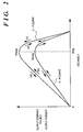
- Fig. 2 is a graph showing an example of characteristic curves, in which the output voltage from the solar cell is plotted along the abscissa, and the output command value and the output power of the power conversion means 2 are plotted along the ordinate.
- the power supplied from the power conversion means 2 to the load 3 changes in proportion to the output command value, as shown in Fig. 2. As the output command value becomes large, a higher power is supplied from the power conversion means 2.
- the output voltage of the battery power supply 1 is a value Vmp at which the output power of the power conversion means 2 is a maximum value Pmax
- the output command value is a maximum value Kmax. Therefore, when a set voltage for maximizing the output command value is set, the power supplied from the battery power supply 1 to the load 3 through the power conversion means 2 is maximized.
- the voltage setting means 4 fetches the output command value and compares it with a previous output command value.
- a voltage to be subsequently set is changed in the same direction as in the previous operation. More specifically, when the set voltage is increased in the previous operation (mode (b) in Fig. 2), the set voltage is also increased in the next operation. If the set voltage is decreased in the previous operation (mode (c) in Fig. 2), the set voltage is decreased in the next operation.
- the output command value decreases, the set voltage to be subsequently set is changed in a direction opposite to that in the previous operation. That is, if the set voltage is increased in the previous operation (mode (d) in Fig.
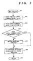
- Fig. 3 is a flow chart showing an example of this operation.
- a previous output command value K1 is stored as K1P (302).
- a new output command value K1 and a voltage V1 are read (303).
- the output command values K1 and K1P are compared with each other to check a variation in output command value. In this case, it is determined whether the output command value increases (304). If the output command value does not increase (i.e., if NO in 304), the searching direction is reversed, i.e., the direction of changing the output command value is reversed (305). After the searching direction is reversed, or if the output command value increases (i.e., if YES in 304), the operating voltage is set in accordance with the change direction and the previous operating voltage (306). This operation is repeatedly performed (307).
- the above operation is repeatedly performed at a predetermined period, and the voltage of the battery power supply 1 is controlled such that the power supplied from the power conversion means 2 to the load 3 is maximized.
- a solar power generation system using a power control method of the second embodiment has an arrangement as shown in Fig. 1, as in the first embodiment.
- a power control system different from the first embodiment will be described below with reference to Fig. 4.
- Fig. 4 is a graph showing characteristic curves at various times, in which the output voltage from a solar cell serving as a battery power supply 1 is plotted along the abscissa, and the output command value is plotted along the ordinate.
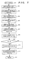
- Fig. 5 is a flow chart showing an operation to be described below.
- a set voltage is defined as V1 first. Control is performed by a voltage control means 5 such that the output voltage from the battery power supply 1 becomes the set voltage. At time tl, sampling is performed to fetch the output voltage V1 from the battery power supply 1 and an output command value K1 at an operating point 1 (502).
- Control is performed by the voltage control means 5 such that the output voltage from the battery power supply 1 becomes the set voltage.
- the output voltage V2 and an output command value K2 at an operating point 2 are fetched (504).
- the set voltage is defined as V1 again (505).
- the output voltage is controlled by the voltage control means 5.
- the variation in solar radiation is estimated on the basis of the difference between the output command values for the same set voltage value V1.
- the variation in output power of the solar cell is almost proportional to the variation in solar radiation.
- the output power of a power conversion means 2 is almost proportional to the input power.
- the output command value is proportional to the output power of the power conversion means 2.
- the difference ⁇ K is calculated (507).
- the output command value K2 is corrected using the difference ⁇ K, i.e., information representing a change in solar radiation (508).
- the normal sampling period Ts is as short as about 1/30 sec, so that the change rate of solar radiation from time tl to time t3 can be regarded as constant. Near the operating point at which the maximum output can be obtained, the difference between the output command values for the voltages V1 and V2 is small. Therefore, the rate of change in output command value caused by the variation in solar radiation for a period corresponding to the sampling period Ts can be regarded as constant for the voltages V1 and V2.
- the output command values at the operating points 3 and 2' are compared with each other, thereby determining the next searching direction. More specifically, since the output command value K3 at the operating point 3 is larger than the output command value K2' at the operating point 2', the operating point at which the output command value, i.e., the operating point at which the maximum power can be obtained is smaller than that for the operating voltage V1. Therefore, the next searching direction, i.e., the voltage change direction is determined as "decrease". That is, K2' > K3 is determined (509), and the change direction is reversed in accordance with the determination result (510) as needed (i.e., if NO in 509). Thereafter, the operating voltage is set in accordance with the change direction and the previous operating voltage.
- the operating point at which the maximum power can be supplied from the power conversion means 2 can be tracked.
- Still another embodiment (third embodiment) of the present invention will be described below.
- a solar power generation system using a power control method of the third embodiment has an arrangement as shown in Fig. 1, as in the first and second embodiments.
- a power control method different from those described above will be described below with reference to Fig. 6.
- Fig. 6 is a graph showing characteristic curves at various times, in which the output voltage from the solar cell is plotted along the abscissa, and the output command value is plotted along the ordinate.
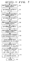
- Fig. 7 is a flow chart showing an operation to be described below.
- a set voltage is defined as V1 first. Control is performed by a voltage control means 5 such that the output voltage from a battery power supply 1 becomes the set voltage. At time tl, sampling is performed to fetch the output voltage V1 from the battery power supply 1 and an output command value K1 at an operating point 1 (702).
- Control is performed by the voltage control means 5 such that the output voltage from the battery power supply 1 becomes the set voltage.
- the output voltage V2 and an output command value K2 at an operating point 2 are fetched (704) .
- the set voltage is defined as V1 again (707).
- the output voltage is controlled by the voltage control means 5.
- V1 V4
- the output power of a power conversion means 2 is almost proportional to the input power.
- the output command value is proportional to the output power of the power conversion means 2. For this reason, the variation in output command value is almost proportional to the variation in solar radiation.
- the output power and output command value of the power conversion means 2 are also almost proportional to the variation in solar radiation as far as the input power varies only for a short period corresponding to the sampling period.
- Data is corrected using the difference ⁇ K, i.e., information representing a change in solar radiation (710 and 711).
- the normal sampling period Ts is as short as about 1/30 sec, so that the change rate of solar radiation from time t1 to time t4 can be regarded as constant. Near the operating point at which the maximum output can be obtained from the inverter, the difference between the output command values from the inverter for the voltages V1 and V2 or V3 is small. Therefore, the rate of change in output command value caused by the variation in solar radiation for a period corresponding to the sampling period Ts can be regarded as constant for the operating voltages V1 and V2 or V3.
- an output command value ⁇ K x (2/3), which corresponds to the change mount of solar radiation from time t2 to time t4, must be added to the output command value K2:
- K2' K2 + ⁇ K x (2/3)
- an output command value ⁇ K x (1/3), which corresponds to the change mount of solar radiation from time t3 to time t4, must be added to the output command value K3:
- K3' K3 + ⁇ K x (1/3)
- the next operating voltage is determined on the basis of the data at the three operating points 2', 3', and 4 in the following manner.
- the voltage vs. output command value characteristic curve at time t4 is approximated using a quadratic curve on the basis of the voltages and output command values at the operating points 2', 3', and 4. Normally, curve approximation within a small range can be satisfactorily achieved by a quadratic curve. In addition, since quadratic curve approximation is performed using data at the three points, the quadratic curve for approximation is uniquely defined.
- the voltage is calculated in accordance with this equation (712) and set as a next search start voltage V (713).
- the operating point at which the maximum power can be supplied from the power conversion means 2 can be tracked.
- the power conversion means for converting power from the battery power supply and supplying the power to the load
- the voltage setting means for setting the output voltage from the battery power supply
- the voltage control means for controlling the output command value to the power conversion means such that the voltage value of the battery power supply becomes the set voltage, comprising setting a voltage on the basis of the output command value or the output command value and the set voltage.
- the power control method for the apparatus having the battery power supply, the power conversion means for converting power from the battery power supply and supplying the power to the load, the voltage setting means for setting the output voltage from the battery power supply, and the voltage control means for controlling the output command value to the power conversion means such that the voltage value of the battery power supply becomes the set voltage comprises the steps of changing the output voltage from the battery power supply to fetch the output command value, calculating a fetching variation on the basis of a plurality of output command values for the same voltage, calculating a corrected output command value on the basis of the variation and the output command value, and setting the set voltage on the basis of the corrected output command value or the corrected output command value and the set voltage.
- the power control method and the power control apparatus using this method of the present invention is very useful. Particularly, a very large effect can be provided for a battery power supply system connected to a commercial system.
Landscapes
- Engineering & Computer Science (AREA)
- Power Engineering (AREA)
- Control Of Electrical Variables (AREA)
- Direct Current Feeding And Distribution (AREA)
Applications Claiming Priority (2)
| Application Number | Priority Date | Filing Date | Title |
|---|---|---|---|
| JP7242313A JPH0962387A (ja) | 1995-08-29 | 1995-08-29 | 電池電源の電力制御方法及び装置並びに電池電源システム |
| JP242313/95 | 1995-08-29 |
Publications (2)
| Publication Number | Publication Date |
|---|---|
| EP0762597A2 true EP0762597A2 (de) | 1997-03-12 |
| EP0762597A3 EP0762597A3 (de) | 1997-03-19 |
Family
ID=17087364
Family Applications (1)
| Application Number | Title | Priority Date | Filing Date |
|---|---|---|---|
| EP96306234A Withdrawn EP0762597A3 (de) | 1995-08-29 | 1996-08-28 | Leistungssteuerungsverfahren sowie Gerät und System zur Batteriestromversorgung |
Country Status (3)
| Country | Link |
|---|---|
| US (1) | US5838148A (de) |
| EP (1) | EP0762597A3 (de) |
| JP (1) | JPH0962387A (de) |
Cited By (2)
| Publication number | Priority date | Publication date | Assignee | Title |
|---|---|---|---|---|
| WO2007113358A1 (es) * | 2006-03-31 | 2007-10-11 | Univ Rovira I Virgili | Circuito y procedimiento de control del punto de potencia máxima para fuentes de energía solar y generador solar que incorpora dicho circuito |
| EP2722725A1 (de) * | 2012-10-16 | 2014-04-23 | Mitsubishi Electric R&D Centre Europe B.V. | Vorrichtung zur Verfolgung eines Punktes maximaler Leistung einer Stromquelle |
Families Citing this family (85)
| Publication number | Priority date | Publication date | Assignee | Title |
|---|---|---|---|---|
| JP3416461B2 (ja) * | 1997-05-30 | 2003-06-16 | キヤノン株式会社 | 太陽電池充電制御装置 |
| CN1161678C (zh) * | 1998-03-30 | 2004-08-11 | 三洋电机株式会社 | 太阳能发电装置 |
| US6005373A (en) * | 1998-10-27 | 1999-12-21 | Micron Technology, Inc. | System with anticipatory power supply load signal |
| JP2000284006A (ja) * | 1999-01-27 | 2000-10-13 | Canon Inc | 発電システムに用いられる情報表示装置、太陽光発電システム、情報中継装置、情報表示方法、情報中継方法、コンピュータプロダクト、および情報伝送方法 |
| KR20010097485A (ko) * | 2000-04-24 | 2001-11-08 | 이형도 | 로드유무에 따른 전압 센싱 이원화 장치 |
| WO2003065564A1 (en) * | 2002-01-31 | 2003-08-07 | Fuji Electric Holdings Co.,Ltd. | Method and device for controlling photovoltaic inverter, and feed water device |
| WO2004077576A1 (en) * | 2003-02-25 | 2004-09-10 | Vhf Technologies Sa | Photovoltaic device |
| US7256566B2 (en) * | 2003-05-02 | 2007-08-14 | Ballard Power Systems Corporation | Method and apparatus for determining a maximum power point of photovoltaic cells |
| JP2004336943A (ja) * | 2003-05-09 | 2004-11-25 | Canon Inc | 電力変換器 |
| US7269036B2 (en) * | 2003-05-12 | 2007-09-11 | Siemens Vdo Automotive Corporation | Method and apparatus for adjusting wakeup time in electrical power converter systems and transformer isolation |
| WO2004107543A2 (en) | 2003-05-28 | 2004-12-09 | Beacon Power Corporation | Power converter for a solar panel |
| EP1911101B1 (de) * | 2005-07-20 | 2011-05-04 | Ecosol Solar Technologies Inc. | Photovoltaische stromausgabebenutzende einrichtung |
| US11881814B2 (en) | 2005-12-05 | 2024-01-23 | Solaredge Technologies Ltd. | Testing of a photovoltaic panel |
| US10693415B2 (en) | 2007-12-05 | 2020-06-23 | Solaredge Technologies Ltd. | Testing of a photovoltaic panel |
| US7900361B2 (en) * | 2006-12-06 | 2011-03-08 | Solaredge, Ltd. | Current bypass for distributed power harvesting systems using DC power sources |
| US8013472B2 (en) | 2006-12-06 | 2011-09-06 | Solaredge, Ltd. | Method for distributed power harvesting using DC power sources |
| US11569659B2 (en) | 2006-12-06 | 2023-01-31 | Solaredge Technologies Ltd. | Distributed power harvesting systems using DC power sources |
| US9112379B2 (en) | 2006-12-06 | 2015-08-18 | Solaredge Technologies Ltd. | Pairing of components in a direct current distributed power generation system |
| US11888387B2 (en) | 2006-12-06 | 2024-01-30 | Solaredge Technologies Ltd. | Safety mechanisms, wake up and shutdown methods in distributed power installations |
| US8473250B2 (en) | 2006-12-06 | 2013-06-25 | Solaredge, Ltd. | Monitoring of distributed power harvesting systems using DC power sources |
| US9130401B2 (en) | 2006-12-06 | 2015-09-08 | Solaredge Technologies Ltd. | Distributed power harvesting systems using DC power sources |
| US8618692B2 (en) | 2007-12-04 | 2013-12-31 | Solaredge Technologies Ltd. | Distributed power system using direct current power sources |
| US11855231B2 (en) | 2006-12-06 | 2023-12-26 | Solaredge Technologies Ltd. | Distributed power harvesting systems using DC power sources |
| US8816535B2 (en) | 2007-10-10 | 2014-08-26 | Solaredge Technologies, Ltd. | System and method for protection during inverter shutdown in distributed power installations |
| US9088178B2 (en) | 2006-12-06 | 2015-07-21 | Solaredge Technologies Ltd | Distributed power harvesting systems using DC power sources |
| US11309832B2 (en) | 2006-12-06 | 2022-04-19 | Solaredge Technologies Ltd. | Distributed power harvesting systems using DC power sources |
| US8384243B2 (en) | 2007-12-04 | 2013-02-26 | Solaredge Technologies Ltd. | Distributed power harvesting systems using DC power sources |
| US11687112B2 (en) | 2006-12-06 | 2023-06-27 | Solaredge Technologies Ltd. | Distributed power harvesting systems using DC power sources |
| US12316274B2 (en) | 2006-12-06 | 2025-05-27 | Solaredge Technologies Ltd. | Pairing of components in a direct current distributed power generation system |
| US11735910B2 (en) | 2006-12-06 | 2023-08-22 | Solaredge Technologies Ltd. | Distributed power system using direct current power sources |
| US8319483B2 (en) | 2007-08-06 | 2012-11-27 | Solaredge Technologies Ltd. | Digital average input current control in power converter |
| US8947194B2 (en) * | 2009-05-26 | 2015-02-03 | Solaredge Technologies Ltd. | Theft detection and prevention in a power generation system |
| US8319471B2 (en) * | 2006-12-06 | 2012-11-27 | Solaredge, Ltd. | Battery power delivery module |
| US20080144294A1 (en) * | 2006-12-06 | 2008-06-19 | Meir Adest | Removal component cartridge for increasing reliability in power harvesting systems |
| US8963369B2 (en) | 2007-12-04 | 2015-02-24 | Solaredge Technologies Ltd. | Distributed power harvesting systems using DC power sources |
| US11296650B2 (en) | 2006-12-06 | 2022-04-05 | Solaredge Technologies Ltd. | System and method for protection during inverter shutdown in distributed power installations |
| EP3561881A1 (de) * | 2007-12-05 | 2019-10-30 | Solaredge Technologies Ltd. | Prüfung eines fotovoltaikplanels |
| EP3496258B1 (de) | 2007-12-05 | 2025-02-05 | Solaredge Technologies Ltd. | Sicherheitsmechanismus in verteilten strominstallationen |
| WO2009072075A2 (en) | 2007-12-05 | 2009-06-11 | Solaredge Technologies Ltd. | Photovoltaic system power tracking method |
| US8049523B2 (en) | 2007-12-05 | 2011-11-01 | Solaredge Technologies Ltd. | Current sensing on a MOSFET |
| US11264947B2 (en) | 2007-12-05 | 2022-03-01 | Solaredge Technologies Ltd. | Testing of a photovoltaic panel |
| EP2232690B1 (de) | 2007-12-05 | 2016-08-31 | Solaredge Technologies Ltd. | Parallel geschaltete umrichter |
| EP4145691A1 (de) | 2008-03-24 | 2023-03-08 | Solaredge Technologies Ltd. | Schaltwandler mit einem hilfskommutierungsschaltkreis zur nullstromschaltung |
| EP3121922B1 (de) | 2008-05-05 | 2020-03-04 | Solaredge Technologies Ltd. | Gleichstromleistungskombinierer |
| US8630098B2 (en) * | 2008-06-12 | 2014-01-14 | Solaredge Technologies Ltd. | Switching circuit layout with heatsink |
| WO2010002960A1 (en) * | 2008-07-01 | 2010-01-07 | Satcon Technology Corporation | Photovoltaic dc/dc micro-converter |
| US9048353B2 (en) | 2008-07-01 | 2015-06-02 | Perfect Galaxy International Limited | Photovoltaic DC/DC micro-converter |
| US8264195B2 (en) | 2008-10-01 | 2012-09-11 | Paceco Corp. | Network topology for monitoring and controlling a solar panel array |
| JP2012527767A (ja) * | 2009-05-22 | 2012-11-08 | ソラレッジ テクノロジーズ リミテッド | 電気絶縁された熱放散接続箱 |
| US8303349B2 (en) | 2009-05-22 | 2012-11-06 | Solaredge Technologies Ltd. | Dual compressive connector |
| US8690110B2 (en) | 2009-05-25 | 2014-04-08 | Solaredge Technologies Ltd. | Bracket for connection of a junction box to photovoltaic panels |
| US12418177B2 (en) | 2009-10-24 | 2025-09-16 | Solaredge Technologies Ltd. | Distributed power system using direct current power sources |
| US8710699B2 (en) | 2009-12-01 | 2014-04-29 | Solaredge Technologies Ltd. | Dual use photovoltaic system |
| US8766696B2 (en) | 2010-01-27 | 2014-07-01 | Solaredge Technologies Ltd. | Fast voltage level shifter circuit |
| FR2961040B1 (fr) * | 2010-06-04 | 2012-06-29 | Commissariat Energie Atomique | Circuit convertisseur et systeme electronique comportant un tel circuit |
| JP4988018B2 (ja) * | 2010-07-29 | 2012-08-01 | 株式会社ダイヘン | 太陽光発電制御装置 |
| US10673229B2 (en) | 2010-11-09 | 2020-06-02 | Solaredge Technologies Ltd. | Arc detection and prevention in a power generation system |
| GB2485527B (en) | 2010-11-09 | 2012-12-19 | Solaredge Technologies Ltd | Arc detection and prevention in a power generation system |
| US10673222B2 (en) | 2010-11-09 | 2020-06-02 | Solaredge Technologies Ltd. | Arc detection and prevention in a power generation system |
| US10230310B2 (en) | 2016-04-05 | 2019-03-12 | Solaredge Technologies Ltd | Safety switch for photovoltaic systems |
| GB2486408A (en) | 2010-12-09 | 2012-06-20 | Solaredge Technologies Ltd | Disconnection of a string carrying direct current |
| GB2483317B (en) | 2011-01-12 | 2012-08-22 | Solaredge Technologies Ltd | Serially connected inverters |
| US8922185B2 (en) | 2011-07-11 | 2014-12-30 | Solarbridge Technologies, Inc. | Device and method for global maximum power point tracking |
| US8570005B2 (en) | 2011-09-12 | 2013-10-29 | Solaredge Technologies Ltd. | Direct current link circuit |
| GB2498365A (en) | 2012-01-11 | 2013-07-17 | Solaredge Technologies Ltd | Photovoltaic module |
| GB2498790A (en) | 2012-01-30 | 2013-07-31 | Solaredge Technologies Ltd | Maximising power in a photovoltaic distributed power system |
| US9853565B2 (en) | 2012-01-30 | 2017-12-26 | Solaredge Technologies Ltd. | Maximized power in a photovoltaic distributed power system |
| GB2498791A (en) | 2012-01-30 | 2013-07-31 | Solaredge Technologies Ltd | Photovoltaic panel circuitry |
| GB2499991A (en) | 2012-03-05 | 2013-09-11 | Solaredge Technologies Ltd | DC link circuit for photovoltaic array |
| EP3499695B1 (de) | 2012-05-25 | 2024-09-18 | Solaredge Technologies Ltd. | Schaltung für verbundene gleichstromquellen |
| US10115841B2 (en) | 2012-06-04 | 2018-10-30 | Solaredge Technologies Ltd. | Integrated photovoltaic panel circuitry |
| US9941813B2 (en) | 2013-03-14 | 2018-04-10 | Solaredge Technologies Ltd. | High frequency multi-level inverter |
| US9548619B2 (en) | 2013-03-14 | 2017-01-17 | Solaredge Technologies Ltd. | Method and apparatus for storing and depleting energy |
| EP2779251B1 (de) | 2013-03-15 | 2019-02-27 | Solaredge Technologies Ltd. | Umgehungsmechanismus |
| CN103513693B (zh) * | 2013-09-29 | 2016-08-10 | 沈阳工业大学 | 基于单变量电流法光伏发电最大功率跟踪控制系统的控制方法 |
| US10256743B2 (en) * | 2013-10-03 | 2019-04-09 | City University Of Hong Kong | Method and apparatus for regulating an electrical power source based on global and local maximum load power |
| US9318974B2 (en) | 2014-03-26 | 2016-04-19 | Solaredge Technologies Ltd. | Multi-level inverter with flying capacitor topology |
| US11081608B2 (en) | 2016-03-03 | 2021-08-03 | Solaredge Technologies Ltd. | Apparatus and method for determining an order of power devices in power generation systems |
| US10599113B2 (en) | 2016-03-03 | 2020-03-24 | Solaredge Technologies Ltd. | Apparatus and method for determining an order of power devices in power generation systems |
| CN107153212B (zh) | 2016-03-03 | 2023-07-28 | 太阳能安吉科技有限公司 | 用于映射发电设施的方法 |
| US11177663B2 (en) | 2016-04-05 | 2021-11-16 | Solaredge Technologies Ltd. | Chain of power devices |
| US12057807B2 (en) | 2016-04-05 | 2024-08-06 | Solaredge Technologies Ltd. | Chain of power devices |
| US11018623B2 (en) | 2016-04-05 | 2021-05-25 | Solaredge Technologies Ltd. | Safety switch for photovoltaic systems |
| US11056875B2 (en) * | 2018-02-23 | 2021-07-06 | Maxim Integrated Products, Inc. | Systems and methods for gate driver with field-adjustable UVLO |
| CN115060961A (zh) * | 2022-03-09 | 2022-09-16 | 深圳市世纪云芯科技有限公司 | 供电方法、电压测量方法和装置 |
Family Cites Families (12)
| Publication number | Priority date | Publication date | Assignee | Title |
|---|---|---|---|---|
| FR2175653B1 (de) * | 1972-03-17 | 1977-04-01 | Labo Cent Telecommunicat | |
| DE2903559A1 (de) * | 1979-01-31 | 1980-12-18 | Eckhard Kienscherf | Solargenerator-leistungsadapter |
| FR2485827A1 (fr) * | 1980-06-26 | 1981-12-31 | Aerospatiale | Procede et systeme pour la production de puissance photovoltaique |
| US4404472A (en) * | 1981-12-28 | 1983-09-13 | General Electric Company | Maximum power control for a solar array connected to a load |
| DE3212022A1 (de) * | 1982-03-31 | 1983-10-06 | Siemens Ag | Verfahren und vorrichtung zum selbsttaetigen einstellen des optimalen arbeitspunktes einer gleichspannungsquelle |
| US4649334A (en) * | 1984-10-18 | 1987-03-10 | Kabushiki Kaisha Toshiba | Method of and system for controlling a photovoltaic power system |
| JPS6285312A (ja) * | 1985-10-09 | 1987-04-18 | Toshiba Corp | 電池電源の最大電力制御方法 |
| US4794272A (en) * | 1987-01-20 | 1988-12-27 | The Aerospace Corporation | Power regulator utilizing only battery current monitoring |
| JP2766407B2 (ja) * | 1991-08-20 | 1998-06-18 | 株式会社東芝 | 太陽光発電用インバータの制御装置 |
| US5327071A (en) * | 1991-11-05 | 1994-07-05 | The United States Of America As Represented By The Administrator Of The National Aeronautics & Space Administration | Microprocessor control of multiple peak power tracking DC/DC converters for use with solar cell arrays |
| JP2935311B2 (ja) * | 1992-07-24 | 1999-08-16 | 関西日本電気株式会社 | 充電回路 |
| JP3263444B2 (ja) * | 1992-09-30 | 2002-03-04 | シャープ株式会社 | 太陽電池利用給電システム |
-
1995
- 1995-08-29 JP JP7242313A patent/JPH0962387A/ja active Pending
-
1996
- 1996-08-28 EP EP96306234A patent/EP0762597A3/de not_active Withdrawn
- 1996-08-28 US US08/703,800 patent/US5838148A/en not_active Expired - Lifetime
Cited By (2)
| Publication number | Priority date | Publication date | Assignee | Title |
|---|---|---|---|---|
| WO2007113358A1 (es) * | 2006-03-31 | 2007-10-11 | Univ Rovira I Virgili | Circuito y procedimiento de control del punto de potencia máxima para fuentes de energía solar y generador solar que incorpora dicho circuito |
| EP2722725A1 (de) * | 2012-10-16 | 2014-04-23 | Mitsubishi Electric R&D Centre Europe B.V. | Vorrichtung zur Verfolgung eines Punktes maximaler Leistung einer Stromquelle |
Also Published As
| Publication number | Publication date |
|---|---|
| JPH0962387A (ja) | 1997-03-07 |
| EP0762597A3 (de) | 1997-03-19 |
| US5838148A (en) | 1998-11-17 |
Similar Documents
| Publication | Publication Date | Title |
|---|---|---|
| US5838148A (en) | Power control method and apparatus for battery power supply and battery power supply system | |
| JP2810630B2 (ja) | 太陽電池の電力制御装置、電力制御システム、電力制御方法及び電圧電流出力特性の測定方法 | |
| JP2771096B2 (ja) | 電力制御装置、電力制御方法及び電力発生装置 | |
| US5932994A (en) | Solar cell power source device | |
| JP4457692B2 (ja) | 最大電力追尾制御方法及び電力変換装置 | |
| US8450883B2 (en) | Maximum power point tracking control apparatus for solar battery | |
| US20080183338A1 (en) | Ripple correlation control based on limited sampling | |
| US8866465B2 (en) | Nanosatellite photovoltaic regulator | |
| US20060290317A1 (en) | Maximum power point motor control | |
| US20130328406A1 (en) | Control system for solar power conversion unit, control method for the unit, and solar power generation system | |
| JPH08227324A (ja) | 太陽光発電装置 | |
| JPH1041535A (ja) | 最大電力点の検出回路 | |
| US20130063117A1 (en) | Maximum power point tracking method | |
| JPH08123563A (ja) | 太陽光発電システムならびにその電力制御装置および方法 | |
| US20120310436A1 (en) | Method of operating a maximum power point tracker | |
| JP3563865B2 (ja) | 太陽電池の電力制御装置 | |
| JP3091400B2 (ja) | 太陽光発電制御装置 | |
| US9608561B2 (en) | Power generation control apparatus, solar power generation system, and power generation control method | |
| JP2002108466A (ja) | 電力制御装置およびその制御方法、並びに、発電装置 | |
| JPH09261949A (ja) | Dc/dcコンバータおよび太陽光発電システム | |
| JP3359206B2 (ja) | 電池電源の電力制御装置 | |
| US9086716B2 (en) | Method for obtaining information enabling the determination of a characteristic of a power source | |
| CN114825449B (zh) | 一种分布式光储高效利用的柔性供电系统 | |
| Stamenic et al. | Novel microprocessor controlled real time MPPT for photovoltaic charging applications | |
| KR101128386B1 (ko) | 태양광 발전 시스템 |
Legal Events
| Date | Code | Title | Description |
|---|---|---|---|
| PUAI | Public reference made under article 153(3) epc to a published international application that has entered the european phase |
Free format text: ORIGINAL CODE: 0009012 |
|
| PUAL | Search report despatched |
Free format text: ORIGINAL CODE: 0009013 |
|
| AK | Designated contracting states |
Kind code of ref document: A2 Designated state(s): CH DE IT LI |
|
| AK | Designated contracting states |
Kind code of ref document: A3 Designated state(s): CH DE IT LI |
|
| 17P | Request for examination filed |
Effective date: 19970730 |
|
| 17Q | First examination report despatched |
Effective date: 19981229 |
|
| GRAG | Despatch of communication of intention to grant |
Free format text: ORIGINAL CODE: EPIDOS AGRA |
|
| GRAG | Despatch of communication of intention to grant |
Free format text: ORIGINAL CODE: EPIDOS AGRA |
|
| STAA | Information on the status of an ep patent application or granted ep patent |
Free format text: STATUS: THE APPLICATION HAS BEEN WITHDRAWN |
|
| 18W | Application withdrawn |
Effective date: 20051213 |