EP0762601A1 - Verbesserter Wechselstromgeneratorlaüfer, insbesondere für Kraftwagen - Google Patents
Verbesserter Wechselstromgeneratorlaüfer, insbesondere für Kraftwagen Download PDFInfo
- Publication number
- EP0762601A1 EP0762601A1 EP96401721A EP96401721A EP0762601A1 EP 0762601 A1 EP0762601 A1 EP 0762601A1 EP 96401721 A EP96401721 A EP 96401721A EP 96401721 A EP96401721 A EP 96401721A EP 0762601 A1 EP0762601 A1 EP 0762601A1
- Authority
- EP
- European Patent Office
- Prior art keywords
- rotor
- alternator
- arms
- alternator according
- fans
- Prior art date
- Legal status (The legal status is an assumption and is not a legal conclusion. Google has not performed a legal analysis and makes no representation as to the accuracy of the status listed.)
- Granted
Links
Images


Classifications
-
- H—ELECTRICITY
- H02—GENERATION; CONVERSION OR DISTRIBUTION OF ELECTRIC POWER
- H02K—DYNAMO-ELECTRIC MACHINES
- H02K21/00—Synchronous motors having permanent magnets; Synchronous generators having permanent magnets
- H02K21/02—Details
- H02K21/04—Windings on magnets for additional excitation ; Windings and magnets for additional excitation
- H02K21/042—Windings on magnets for additional excitation ; Windings and magnets for additional excitation with permanent magnets and field winding both rotating
- H02K21/044—Rotor of the claw pole type
-
- H—ELECTRICITY
- H02—GENERATION; CONVERSION OR DISTRIBUTION OF ELECTRIC POWER
- H02K—DYNAMO-ELECTRIC MACHINES
- H02K1/00—Details of the magnetic circuit
- H02K1/06—Details of the magnetic circuit characterised by the shape, form or construction
- H02K1/22—Rotating parts of the magnetic circuit
- H02K1/32—Rotating parts of the magnetic circuit with channels or ducts for flow of cooling medium
- H02K1/325—Rotating parts of the magnetic circuit with channels or ducts for flow of cooling medium between salient poles
-
- H—ELECTRICITY
- H02—GENERATION; CONVERSION OR DISTRIBUTION OF ELECTRIC POWER
- H02K—DYNAMO-ELECTRIC MACHINES
- H02K9/00—Arrangements for cooling or ventilating
- H02K9/02—Arrangements for cooling or ventilating by ambient air flowing through the machine
- H02K9/04—Arrangements for cooling or ventilating by ambient air flowing through the machine having means for generating a flow of cooling medium
- H02K9/06—Arrangements for cooling or ventilating by ambient air flowing through the machine having means for generating a flow of cooling medium with fans or impellers driven by the machine shaft
Definitions
- the present invention relates generally to alternators in particular for motor vehicles, and more particularly an improvement to alternators called internal ventilation.
- An alternator of this type conventionally comprises a rotor mounted on a shaft, said shaft being pivotally mounted in two half-bearings or half-casings on which the stator is mounted.
- the rotor is flanked by two fans which ensure, during rotation, ventilation and cooling of the alternator members through air inlet and outlet openings formed in the casing.
- each fan is produced by cutting and bending sheet steel, and is fixed to the respective flank of the rotor by welding.
- FR-A-2 609 583 discloses an alternator as defined in the preamble of claim 1, which allows easy and simple mounting of the rotor, with a reduced number of parts, and which also makes it possible to reduce the overall cost of the fans in an alternator with internal ventilation, to reduce noise and to protect the rotor against external agents.
- the present invention aims to improve the efficiency of an alternator of this type, and more precisely to increase the rotor flux by particularly simple means and economical, not complicating the manufacturing of the alternator.
- the invention provides for this purpose an alternator as defined in claim 1.
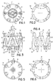
- FIG. 1 to 6 there is shown a set of shaft and rotor of a fan alternator.
- the shaft is designated by the reference A.
- the rotor comprises, conventionally in itself, two pole wheels 10, 20 sheltering between them a rotor winding and comprising pole horns 11, 21 of generally triangular shape, nested one inside the other. others by leaving between them, over their entire axial extent, interstices of essentially constant width.
- two fans are provided consisting of a single piece, generally indicated by the reference 30, preferably made in one piece by molding of plastic material.
- This part comprises a series of arms 35 oriented obliquely to axial planes, defining two by two a "V". These arms 35 meet at their ends in meeting regions, respectively 33 and 34, arranged as a whole in two circles centered on the axis of the rotor and spaced along said axis.
- From these joining regions extend, for example in planes parallel to the axis of the rotor, blades, respectively 31 and 32, extending outward from said circles.
- the frame of the part 30, constituted by the arms 35 and the joining parts, is shaped and dimensioned so that each "V" formed by two adjacent arms, on one side as on the other, can receive during from the rotor assembly a respective pole horn, 11 or 21.
- each arm 35 is designed so that its outer surface is substantially flush with the surfaces of the pole horns, together defining a cylinder of revolution having as its axis that of the rotor.
- the blades 31 constitute the so-called front fan (drive pulley side), while the blades 32 constitute the so-called rear fan (righting and regulation side).
- the shape, number and distribution of the blades 31 and 32 can be entirely arbitrary, the only constraints being that these blades must extend from the joining regions 33, 34 and not obstruct the axial engagement of the two pole wheels 10, 20 on either side of the part 30.
- FIG. 7 there is shown a second embodiment of the invention. This differs from the first essentially in that some of the arms 35 of the part 30 are hollowed out along their length to define a path of ventilation air going from the rear side of the alternator (bottom in FIG. 9) towards the front side (top).
- some of the arms 35 have over their length, at the edge between their outer face and their lateral face adjacent to a pole horn 21, a recess 36' of rectangular or square section (see in particular FIG. 10b), forming a channel, which extends over the length of the arm in question and which also passes through the corresponding joining parts 33, 34 to open axially on the terminal radial face of the part 30, in the vicinity of the blades 31, 32. More specifically, a channel 36 'opens on one side between two adjacent blades 31 and on the other side immediately outside a similar group of two adjacent blades.
- the arms 35 ′ in which the recesses 36 ′ are made are arms which extend from the rear towards the front of the rotor (that is to say from bottom to top in Figure 9), obliquely in the opposite direction to that of rotation. It can be all the arms having this orientation, that is to say one in two, or only some of these arms.
- the orientation of the air paths defined by the recesses 36 'relative to the direction of rotation of the rotor is such that an air flow is created, indicated by the arrow F1 in FIG. 9, between the rear and the front of the rotor, this air then being discharged radially by the front fan at the same time as the air introduced axially from the same side.
- FIGS. 14 to 20 illustrate a third embodiment of the present invention, which differs from the second essentially in that the arms in which the ventilation channels are formed have an inclination opposite to that of the arms 35 ′. More specifically, the arms 35 "which, with respect to the direction of rotation of the rotor, extend from the front to the rear of the rotor obliquely in the opposite direction to that of rotation, include recesses 36 "which cause a flow of ventilation air from the front side to the rear side of the rotor, flow designated by arrow F3 in FIG. 16.
- the channels 36 " produced on all the arms having this orientation, or only on some of them, open on one side between two adjacent blades 32 and on the other side immediately outside, upstream side, a similar group of blades 31.
- the fourth embodiment of the invention combines the provisions of the second and third embodiments in that it comprises, in the arms 35 ′ having the above-mentioned first inclination, channels 36 ′ ventilation from the rear to the front, and in the arms 35 "having the second inclination mentioned above, channels 36" from ventilation from the front to the rear, the channels 36 'and 36 “meeting, on the side before, at the level of the parts 33 for joining between arms.
- the arms fitted with channels can be all the arms of the part 30 or only some of these arms.
- FIGS. 28 to 33 A fifth embodiment of the invention is shown in FIGS. 28 to 33.
- it is sought to produce a large flow of ventilation air from the front side to the rear side of the rotor (from top to bottom on Figure 30).
- two arms 35 ′, 35 ′′ of the same “V” pointing towards the front side of the rotor are provided with recesses or channels, designated by the references 37 ′ and 37 ′′, whose inclination with respect to axial planes is as small as possible, and whose cross section decreases progressively from the front side to the rear side.
- each channel 37 ′, 37 ′′ has as its starting point a large notch located immediately adjacent to a group of blades 31 of the front fan, on one side or the other of this group, and for point d arrival a much narrower cut immediately adjacent to a group of blades 32 on the rear side, group angularly offset from the aforementioned group of blades 31.
- the ventilation channels 36 ', 36 ", 37' or 37" are formed at the edges between the outer face (adjacent to the stator) and lateral face (adjacent to a polar horn) of the arm considered.
- the piece 30 can be produced by overmolding on a metallic or other core, for example of steel, of stiffening.
- This core has a profile compatible with the arrangement of the arms 35 which accommodate its different sections.
- FIGS. 34 to 37 show a sixth embodiment of the present invention, in which the part 30 simultaneously constitutes a support for magnetic elements intended to increase the rotor flux of the machine, and therefore its current flow .
- each arm 35 receives along its length an elongated permanent magnet 40, oriented north-south in its transverse direction, so as to have a face of North polarity situated opposite a North pole horn. and a face of South polarity facing the adjacent polar horn, also of South polarity (see in particular Figure 37).
- These magnets are preferably flush with the outside surface of each arm.
- the part 30 provided with magnets 40 is produced by overmolding plastic material on the magnets previously placed in a mold.
- the shape of the magnets is chosen so as to ensure a satisfactory anchoring thereof in the material of the part 30 in particular in the radial direction, so as to withstand the centrifugal force (see in particular Figure 36, where the plastic of the arm 35 penetrates into grooves formed at the longitudinal ends of the magnet).
Landscapes
- Engineering & Computer Science (AREA)
- Power Engineering (AREA)
- Iron Core Of Rotating Electric Machines (AREA)
- Synchronous Machinery (AREA)
Applications Claiming Priority (2)
| Application Number | Priority Date | Filing Date | Title |
|---|---|---|---|
| FR9509426A FR2737617B1 (fr) | 1995-08-02 | 1995-08-02 | Alternateur a moyens de ventilation perfectionnes, notamment pour vehicule automobile |
| FR9509426 | 1995-08-02 |
Publications (2)
| Publication Number | Publication Date |
|---|---|
| EP0762601A1 true EP0762601A1 (de) | 1997-03-12 |
| EP0762601B1 EP0762601B1 (de) | 2001-10-24 |
Family
ID=9481654
Family Applications (1)
| Application Number | Title | Priority Date | Filing Date |
|---|---|---|---|
| EP19960401721 Expired - Lifetime EP0762601B1 (de) | 1995-08-02 | 1996-08-02 | Verbesserter Wechselstromgeneratorlaüfer, insbesondere für Kraftwagen |
Country Status (3)
| Country | Link |
|---|---|
| EP (1) | EP0762601B1 (de) |
| DE (1) | DE69616220T2 (de) |
| FR (1) | FR2737617B1 (de) |
Cited By (3)
| Publication number | Priority date | Publication date | Assignee | Title |
|---|---|---|---|---|
| WO1999008365A1 (en) * | 1997-08-05 | 1999-02-18 | Ford Motor Company | Rotor for an electrical machine |
| FR2798231A1 (fr) * | 1999-09-07 | 2001-03-09 | Mitsubishi Electric Corp | Structure de rotor |
| FR2866993A1 (fr) * | 2004-02-27 | 2005-09-02 | Valeo Equip Electr Moteur | Ensemble rotorique dont au moins un espace intergriffes est obture par le ventilateur |
Families Citing this family (2)
| Publication number | Priority date | Publication date | Assignee | Title |
|---|---|---|---|---|
| FR2912007B1 (fr) * | 2007-01-30 | 2013-01-18 | Valeo Equip Electr Moteur | Rotor de machine electrique tournante comportant une chaine ouverte d'au moins deux elements interpolaires formant barriere magnetique |
| FR3018404B1 (fr) * | 2014-03-04 | 2017-09-08 | Valeo Equip Electr Moteur | Support d'elements magnetiques pour rotor a griffes de machine electrique tournante et rotor a griffes de machine electrique tournante comportant un tel support |
Citations (4)
| Publication number | Priority date | Publication date | Assignee | Title |
|---|---|---|---|---|
| FR2609583A3 (fr) * | 1987-01-09 | 1988-07-15 | Ducellier & Cie | Generatrice sans balai comprenant un ensemble inducteur a elements polaires a griffes |
| US5306977A (en) * | 1991-08-08 | 1994-04-26 | Nippondenso Co., Ltd. | Cooling rotor for an alternator mounted on vehicle |
| US5329199A (en) * | 1992-11-23 | 1994-07-12 | Ford Motor Company | Rotor assembly with molded fans and method for making the same |
| GB2281665A (en) * | 1993-08-30 | 1995-03-08 | Nippon Denso Co | Mounting magnets in a rotor for an AC generator |
-
1995
- 1995-08-02 FR FR9509426A patent/FR2737617B1/fr not_active Expired - Fee Related
-
1996
- 1996-08-02 DE DE1996616220 patent/DE69616220T2/de not_active Expired - Fee Related
- 1996-08-02 EP EP19960401721 patent/EP0762601B1/de not_active Expired - Lifetime
Patent Citations (4)
| Publication number | Priority date | Publication date | Assignee | Title |
|---|---|---|---|---|
| FR2609583A3 (fr) * | 1987-01-09 | 1988-07-15 | Ducellier & Cie | Generatrice sans balai comprenant un ensemble inducteur a elements polaires a griffes |
| US5306977A (en) * | 1991-08-08 | 1994-04-26 | Nippondenso Co., Ltd. | Cooling rotor for an alternator mounted on vehicle |
| US5329199A (en) * | 1992-11-23 | 1994-07-12 | Ford Motor Company | Rotor assembly with molded fans and method for making the same |
| GB2281665A (en) * | 1993-08-30 | 1995-03-08 | Nippon Denso Co | Mounting magnets in a rotor for an AC generator |
Cited By (4)
| Publication number | Priority date | Publication date | Assignee | Title |
|---|---|---|---|---|
| WO1999008365A1 (en) * | 1997-08-05 | 1999-02-18 | Ford Motor Company | Rotor for an electrical machine |
| FR2798231A1 (fr) * | 1999-09-07 | 2001-03-09 | Mitsubishi Electric Corp | Structure de rotor |
| US6369485B1 (en) | 1999-09-07 | 2002-04-09 | Mitsubishi Denki Kabushiki Kaisha | Rotor structure |
| FR2866993A1 (fr) * | 2004-02-27 | 2005-09-02 | Valeo Equip Electr Moteur | Ensemble rotorique dont au moins un espace intergriffes est obture par le ventilateur |
Also Published As
| Publication number | Publication date |
|---|---|
| FR2737617B1 (fr) | 1997-10-24 |
| FR2737617A1 (fr) | 1997-02-07 |
| DE69616220D1 (de) | 2001-11-29 |
| EP0762601B1 (de) | 2001-10-24 |
| DE69616220T2 (de) | 2002-06-27 |
Similar Documents
| Publication | Publication Date | Title |
|---|---|---|
| EP0886366B1 (de) | Wechselstromgenrator mit verbesserten Mitteln zur Kühlung, insbesondere für ein Kraftfahrzeug | |
| FR2676873A1 (fr) | Alternateur triphase pour vehicules automobiles. | |
| WO2024132600A1 (fr) | Stator de machine électrique à flux axial | |
| WO2024132599A1 (fr) | Stator de machine électrique à flux axial | |
| EP0762601B1 (de) | Verbesserter Wechselstromgeneratorlaüfer, insbesondere für Kraftwagen | |
| EP4402779A1 (de) | Wicklungsführung für einen rotor eines elektromotors | |
| WO2022207985A1 (fr) | Rotor de machine électrique tournante | |
| FR3121555A1 (fr) | Stator pour moteur ou générateur sans balais | |
| FR2602925A1 (fr) | Dispositif interne de ventilation pour une machine electrique tournante telle qu'un alternateur | |
| FR2853365A1 (fr) | Dispositif de ventilation | |
| EP2005554B1 (de) | Rotor für eine elektrische rotormaschine mit rillen für magnete | |
| EP4111574B1 (de) | Rotor für einen elektromotor ausgestattet mit permanentmagneten aus kunststoffmaterial | |
| WO2018158517A1 (fr) | Rotor de machine électrique tournante munie d'au moins un roulement à ventilateur intégré | |
| EP3574571A1 (de) | Elektrische drehmaschine mit einer blende zur begrenzung der rückschleife von heissluft | |
| EP3382856A1 (de) | Elektrisch umlaufende maschine mit optimierter kühlung | |
| EP0762615B1 (de) | Lichtmaschine mit interner Lüftungsvorrichtung, insbesondere für Autos | |
| FR3132992A1 (fr) | Machine électrique tournante munie d'un flasque intégrant des élements saillants de dissipation thermique | |
| EP3850727B1 (de) | Rotierende elektrische maschine mit einem aus zwei übergossenen teilen hergestellten lager | |
| FR2797170A1 (fr) | Ensemble d'aspiration | |
| FR3077344A1 (fr) | Helice de ventilateur pour vehicule automobile | |
| FR2858884A1 (fr) | Dispsositif de refroidissement d'un alternateur avec guide d'air | |
| FR3157899A1 (fr) | Support moteur et générateur de flux d’air correspondant d’une installation de chauffage, ventilation et/ou climatisation d’un véhicule notamment automobile | |
| WO2018020188A1 (fr) | Machine electrique tournante munie d'un stator avec un bobinage epingle | |
| FR3164851A1 (fr) | Rotor pour moteur électrique équipé de flasques d’extrémité intégrant des plasto-aimants | |
| WO2025141216A1 (fr) | Support moteur et générateur de flux d'air correspondant d'une installation de chauffage, ventilation et/ou climatisation d'un véhicule notamment automobile |
Legal Events
| Date | Code | Title | Description |
|---|---|---|---|
| PUAI | Public reference made under article 153(3) epc to a published international application that has entered the european phase |
Free format text: ORIGINAL CODE: 0009012 |
|
| AK | Designated contracting states |
Kind code of ref document: A1 Designated state(s): DE ES FR GB IT |
|
| 17P | Request for examination filed |
Effective date: 19970901 |
|
| 17Q | First examination report despatched |
Effective date: 19990416 |
|
| GRAG | Despatch of communication of intention to grant |
Free format text: ORIGINAL CODE: EPIDOS AGRA |
|
| GRAG | Despatch of communication of intention to grant |
Free format text: ORIGINAL CODE: EPIDOS AGRA |
|
| GRAH | Despatch of communication of intention to grant a patent |
Free format text: ORIGINAL CODE: EPIDOS IGRA |
|
| GRAH | Despatch of communication of intention to grant a patent |
Free format text: ORIGINAL CODE: EPIDOS IGRA |
|
| GRAA | (expected) grant |
Free format text: ORIGINAL CODE: 0009210 |
|
| AK | Designated contracting states |
Kind code of ref document: B1 Designated state(s): DE ES FR GB IT |
|
| PG25 | Lapsed in a contracting state [announced via postgrant information from national office to epo] |
Ref country code: IT Free format text: LAPSE BECAUSE OF FAILURE TO SUBMIT A TRANSLATION OF THE DESCRIPTION OR TO PAY THE FEE WITHIN THE PRE;WARNING: LAPSES OF ITALIAN PATENTS WITH EFFECTIVE DATE BEFORE 2007 MAY HAVE OCCURRED AT ANY TIME BEFORE 2007. THE CORRECT EFFECTIVE DATE MAY BE DIFFERENT FROM THE ONE RECORDED.SCRIBED TIME-LIMIT Effective date: 20011024 |
|
| REF | Corresponds to: |
Ref document number: 69616220 Country of ref document: DE Date of ref document: 20011129 |
|
| REG | Reference to a national code |
Ref country code: GB Ref legal event code: IF02 |
|
| GBT | Gb: translation of ep patent filed (gb section 77(6)(a)/1977) |
Effective date: 20020105 |
|
| PG25 | Lapsed in a contracting state [announced via postgrant information from national office to epo] |
Ref country code: ES Free format text: LAPSE BECAUSE OF FAILURE TO SUBMIT A TRANSLATION OF THE DESCRIPTION OR TO PAY THE FEE WITHIN THE PRESCRIBED TIME-LIMIT Effective date: 20020430 |
|
| PLBE | No opposition filed within time limit |
Free format text: ORIGINAL CODE: 0009261 |
|
| STAA | Information on the status of an ep patent application or granted ep patent |
Free format text: STATUS: NO OPPOSITION FILED WITHIN TIME LIMIT |
|
| 26N | No opposition filed | ||
| PGFP | Annual fee paid to national office [announced via postgrant information from national office to epo] |
Ref country code: DE Payment date: 20080811 Year of fee payment: 13 |
|
| PGFP | Annual fee paid to national office [announced via postgrant information from national office to epo] |
Ref country code: GB Payment date: 20080808 Year of fee payment: 13 |
|
| GBPC | Gb: european patent ceased through non-payment of renewal fee |
Effective date: 20090802 |
|
| PG25 | Lapsed in a contracting state [announced via postgrant information from national office to epo] |
Ref country code: DE Free format text: LAPSE BECAUSE OF NON-PAYMENT OF DUE FEES Effective date: 20100302 |
|
| PG25 | Lapsed in a contracting state [announced via postgrant information from national office to epo] |
Ref country code: GB Free format text: LAPSE BECAUSE OF NON-PAYMENT OF DUE FEES Effective date: 20090802 |
|
| REG | Reference to a national code |
Ref country code: FR Ref legal event code: PLFP Year of fee payment: 20 |
|
| PGFP | Annual fee paid to national office [announced via postgrant information from national office to epo] |
Ref country code: FR Payment date: 20150831 Year of fee payment: 20 |