EP0762670A2 - TDMA Kommunikationsverfahren für Basisstation die für verschiedene Zonen verschiedene Frequenzen anwendet und Empfänger dafür - Google Patents
TDMA Kommunikationsverfahren für Basisstation die für verschiedene Zonen verschiedene Frequenzen anwendet und Empfänger dafür Download PDFInfo
- Publication number
- EP0762670A2 EP0762670A2 EP96114632A EP96114632A EP0762670A2 EP 0762670 A2 EP0762670 A2 EP 0762670A2 EP 96114632 A EP96114632 A EP 96114632A EP 96114632 A EP96114632 A EP 96114632A EP 0762670 A2 EP0762670 A2 EP 0762670A2
- Authority
- EP
- European Patent Office
- Prior art keywords
- tdma
- signals
- intermediate frequency
- signal
- frequency
- Prior art date
- Legal status (The legal status is an assumption and is not a legal conclusion. Google has not performed a legal analysis and makes no representation as to the accuracy of the status listed.)
- Withdrawn
Links
- 238000000034 method Methods 0.000 title claims description 27
- 238000004891 communication Methods 0.000 title claims description 11
- 230000001360 synchronised effect Effects 0.000 claims description 24
- 230000005540 biological transmission Effects 0.000 claims description 23
- 238000010586 diagram Methods 0.000 description 8
- 238000001228 spectrum Methods 0.000 description 4
- 108010076504 Protein Sorting Signals Proteins 0.000 description 3
- 230000000694 effects Effects 0.000 description 2
- 230000003321 amplification Effects 0.000 description 1
- 238000006243 chemical reaction Methods 0.000 description 1
- 230000003247 decreasing effect Effects 0.000 description 1
- 238000010295 mobile communication Methods 0.000 description 1
- 238000003199 nucleic acid amplification method Methods 0.000 description 1
- 230000008054 signal transmission Effects 0.000 description 1
Images


Classifications
-
- H—ELECTRICITY
- H04—ELECTRIC COMMUNICATION TECHNIQUE
- H04B—TRANSMISSION
- H04B7/00—Radio transmission systems, i.e. using radiation field
- H04B7/24—Radio transmission systems, i.e. using radiation field for communication between two or more posts
- H04B7/26—Radio transmission systems, i.e. using radiation field for communication between two or more posts at least one of which is mobile
- H04B7/2643—Radio transmission systems, i.e. using radiation field for communication between two or more posts at least one of which is mobile using time-division multiple access [TDMA]
-
- Y—GENERAL TAGGING OF NEW TECHNOLOGICAL DEVELOPMENTS; GENERAL TAGGING OF CROSS-SECTIONAL TECHNOLOGIES SPANNING OVER SEVERAL SECTIONS OF THE IPC; TECHNICAL SUBJECTS COVERED BY FORMER USPC CROSS-REFERENCE ART COLLECTIONS [XRACs] AND DIGESTS
- Y02—TECHNOLOGIES OR APPLICATIONS FOR MITIGATION OR ADAPTATION AGAINST CLIMATE CHANGE
- Y02D—CLIMATE CHANGE MITIGATION TECHNOLOGIES IN INFORMATION AND COMMUNICATION TECHNOLOGIES [ICT], I.E. INFORMATION AND COMMUNICATION TECHNOLOGIES AIMING AT THE REDUCTION OF THEIR OWN ENERGY USE
- Y02D30/00—Reducing energy consumption in communication networks
- Y02D30/70—Reducing energy consumption in communication networks in wireless communication networks
Definitions
- the present invention relates to a TDMA Communicating Method and a TDMA receiving apparatus, in particular, to a TDMA communicating method of a base station that communicates with a plurality of zones that use different radio frequencies and a TDMA receiving apparatus thereof.
- a base station corresponding to TDMA (Time Division Multiple Access) communicating method using a fan-shaped beam antenna for sectoring a service area has a plurality of independent TDMA receiving apparatuses that use different transmission/reception radio frequencies for individual fan-shaped divided zone.
- TDMA Time Division Multiple Access
- Such a sector zone method is mainly used to increase the number of subscriber stations accommodated in the service area of the base station with the TDMA receiving apparatuses having the communication capacity for a predetermined number of subscribers and radio frequency bands thereof.
- Japanese Patent Laid-Open Publication No. 3-206743 shows a sector control system.
- the control channel zone of a radio base station has a non-directional control channel zone.
- the control channel zone is divided into a plurality of sectors. Speech channels are controlled for individual sectors.
- a sector of a mobile station to be connected is determined by a radio loop check.
- Nakayama et al. shows a TDMA communicating method used in a 26 GHz band digital subscriber radio system.
- independent frames are formed for respective divided zones with different radio frequencies.
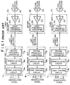
- receiving antennas for three fan-shaped divided zones are disposed. Outdoor units and indoor units corresponding to the receiving antennas are independently disposed.
- the structure of each of the three independent TDMA receiving apparatuses is the same. Only receiving radio frequencies of the TDMA receiving apparatuses are different from each other. Thus, in the following description, the structure of only the first TDMA receiving apparatus will be described.
- a receiving antenna 3a receives a radio frequency burst signal transmitted in the TDMA method by a subscriber station in a particular fan-shaped divided zone.
- the received signal is sent to an outdoor unit 2a disposed adjacent to the receiving antenna 3a.
- the received radio frequency signal is amplified and the received frequency is converted into a first intermediate frequency.
- the resultant signal is sent to a unit connecting cable 4a.
- the unit connecting cable 4a is connected to an indoor unit 1a so as to send the first intermediate frequency signal from the outdoor unit 2a to the indoor unit 1a.
- a demodulated signal is restored from the first intermediate frequency signal.
- information signals of individual subscribers are obtained by synchronizing the TDMA frame.
- the outdoor unit 2a has a low noise amplifier (LNA) 5a and a first frequency converter 6a.
- the low noise amplifier 5a amplifies a received radio frequency signal of a weak power at a predetermined amplification factor with a small internal noise.
- the first frequency converter 6a converts the amplified signal into a first intermediate frequency signal so as to reduce a transmission loss of the signal sent from the unit connecting cable 4a to the indoor unit 1a.
- the indoor unit 1a has a second frequency converter 7a, a demodulating circuit 8a, and a TDMA control circuit 9a.
- the second frequency converter 7a converts the first intermediate frequency signal into a second intermediate frequency signal so as to demodulate the first intermediate frequency signal supplied from the outdoor unit 2a.
- the demodulating circuit 8a inputs the second intermediate frequency signal and outputs a TDMA signal as a demodulated signal of the second intermediate frequency signal.
- the TDMA control circuit 9a inputs the TDMA signal, synchronizes the frames of the TDMA signal, and obtains information data signals of individual subscribers that have been time-division multiplexed.
- the modulated signals that are input to the demodulating circuits 8a, 8b, and 8c should be not always the same frequency modulation signal.
- the second intermediate frequencies converted by the second frequency converters 7a, 7b, and 7c are not always the same frequency.
- the number of TDMA receiving apparatuses disposed in the base station should accord with the number of fan-shaped divided zones as outdoor units and indoor units.
- demodulating circuits and TDMA control circuits are required for individual divided zones.
- the hardware scale increases proportional to the number of divided zones unlike with the structure of which the service area is not sectored.
- An object of the present invention is to share the same functional circuit so as to simply structure the entire apparatus and reduce the size and power consumption thereof.
- the present invention is a time division multiple access (TDMA) communicating method for performing a time division multiple access for a one-point-to-many-point communication between a base station and a plurality of subscriber stations with radio frequencies corresponding to zones, a subscriber station being adapted for transmitting TDMA signals with time slots of a common TDMA synchronous frame in such a manner that the TDMA signals of the subscriber stations does not overlap, the base station being adapted for converting the TDMA signals of the subscriber stations into signals with the same center frequency, combining the powers of the converted signals, and demodulating the resultant signals.
- TDMA time division multiple access
- the number of time slots of the TDMA synchronous frame of the TDMA signals of the subscriber stations is varied corresponding to the density of subscribers of the zones or corresponding to transmission requests of the subscriber stations.
- the TDMA signals are converted into intermediate frequency signals with the same center frequency and then combined corresponding to the above-described TDMA communicating method, signals of individual subscriber stations can be demodulated by the common demodulating unit.
- the frequency converters are adapted for converting TDMA signals with different radio frequencies into intermediate frequency signals with the same frequency so as to input the TDMA signals to a common demodulating circuit.
- the combining unit is adapted for combining the powers of the intermediate frequency signals converted by the frequency converters.
- the TDMA receiving apparatus has the following means.
- the TDMA receiving apparatus has a plurality of antennas, outdoor units disposed adjacent thereto, an indoor unit connected thereto.
- the outdoor units each have a low noise amplifier and a first frequency converter for reducing the power loss of signals supplied to the indoor unit.
- the indoor unit has a plurality of second frequency converters and a power combining unit.
- the second frequency converters are adapted for converting the signals supplied from the outdoor units to intermediate frequency signals with the same intermediate frequency.
- the power combining unit is adapted for combining the powers of the converted signals.
- the indoor unit has a control circuit for obtaining data of each subscriber station from the demodulated data signal having the structure of TDMA frames.
- the indoor unit has a frequency control circuit that supplies a control signal for controlling the frequencies of the second frequency converters so as to externally vary radio frequencies that can be received and demodulated.
- the frequency converters of the TDMA receiving apparatus are adapted for converting TDMA signals with different radio frequencies sent with the same TDMA synchronous frame into intermediate frequency signals with the same frequency.
- the combining unit is adapted for combining the powers of the intermediate frequency signals converted from the TDMA signals assigned to different time slots for signals of subscriber stations.
- the demodulating circuit and the TDMA control circuit can be shared.
- the size of the receiving apparatus can be reduced and thereby the power consumption can be decreased.
- TDMA control is performed for individual divided zones with different radio frequencies corresponding to a common TDMA synchronous frame.
- time slots are assigned to the divided zones so that the time slots do not overlap.
- the total transmission capacity receivable by the base station can be assigned to each divided zone corresponding to the communication traffic amount thereof.
- the difference of the density of subscribers and transmission requests for each divided zone can be properly handled. Consequently, the performance of the base station can be fully obtained.
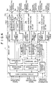
- Fig. 2 is a block diagram showing the structure of a first embodiment of the present invention.
- a first first-intermediate frequency signal, a second first-intermediate frequency signal, and a third first-intermediate frequency signal are sent from a first outdoor unit 2a, a second outdoor unit 2b, and a third outdoor unit 2c to an indoor unit 1 through unit connecting cables 4a to 4c, respectively.
- the input three first-intermediate signals one demodulated signal is obtained.
- the demodulated signal is synchronized with TDMA frames.
- information signals for individual subscribers of all the fan-shaped divided zones are obtained and output to the outside of the indoor unit 1.
- the indoor unit 1 has a demodulating circuit 8, a TDMA control circuit 9, first to third second-frequency converters 7a to 7c, a combining unit 10, and a frequency control circuit.
- the demodulating circuit 8 inputs a second intermediate frequency signal and demodulates the input signal into a TDMA signal.
- the TDMA control circuit 9 synchronizes the demodulated signal corresponding to a TDMA synchronous frame that is common in three fan-shaped divided zones and obtains information signals of subscribe stations of the three fan-shaped divided zones.
- the first to third second-frequency converters 7a to 7c convert the three first-intermediate frequency signals into second-intermediate frequency signals with the same frequency so as to demodulate the first-intermediate frequency signals.
- the combining unit 10 combines the powers of the second-intermediate frequency signals converted by the second-frequency converters 7a to 7c.
- the combining unit 10 is for example a power combining unit composed of a hybrid transformer combiner, resistors combiner, or the like.
- the indoor unit 1 has the frequency control circuit 11 that generates a frequency conversion control signal for controlling the first to third second-frequency converters 7a to 7c corresponding to frequency selection information supplied from the outside of the indoor unit 1.
- Figs. 3(A) and 3(B) are schematic diagrams for comparing TDMA synchronous frame structures and frequency spectrums of the TDMA communication method according to the present invention and the conventional TDMA communicating method.
- each of three fan-shaped divided zone has an independent TDMA synchronous frame.
- Each of the TDMA synchronous frames has a data region that is 20 time slots (TS) assigned to subscriber stations in each fan-shaped divided zone.
- TS time slots
- the frequency spectrum of a radio frequency of each fan-shaped divided zone has a relatively narrow frequency band whose center frequency that is different in each fan-shaped divided zone.
- the resultant TDMA synchronous frame has 60 TS corresponding to the subscriber station in all the fan-shaped divided zones and is common in all the fan-shaped divided zones.
- the frequency spectrums of radio frequencies of the fan-shaped divided zones have center frequencies as with the conventional TDMA synchronous frames.
- the data capacity of the TDMA synchronous frame according to the present invention is three times larger than that of the conventional TDMA synchronous frame, the frequency band is tripled.
- time slots of other zones are treated as blank slots.
- a receiving apparatus that has a larger transmission capacity than that is actually used and a wider frequency band than that of the conventional frame are required.
- a common TDMA synchronous frame for transmitting signals of individual fan-shaped divided zones can be used.
- radio frequency signals of individual fan-shaped divided zones are converted into common second-frequency signals and their powers are combined, since time slots do not overlap, a combined TDMA signal that includes signals of subscribers of all the fan-shaped divided zone can be obtained.
- a picture providing system As an example of which the frequency band and transmission capacity can be increased without a problem, a picture providing system is known.
- a picture providing service such as CATV is performed with radio signals
- the transmission capacity of picture data sent from the base station to the subscriber stations in the down link direction is much larger than the transmission capacity of control data such as request data sent from the subscriber stations to the base station in the up link direction.
- control data such as request data sent from the subscriber stations to the base station in the up link direction.
- asymmetrical communications are required. Consequently, since the transmission capacity and the frequency band of data sent in the up link direction are small, the increases of the transmission capacity and the frequency band of the communicating method of sharing a TDMA synchronous frame may not become a problem in many situations.
- the predetermined number of time slots of the TDMA synchronous frame is equally assigned to each fan-shaped divided zone.
- the transmission capacity can be assigned corresponding to the communication traffic.
- the communication facility can be more effectively used than the above-described embodiment.
- FIG. 4 is a TDMA control circuit.
- the TDMA control circuit shown in Fig. 4 obtains information signals of subscriber stations of three fan-shaped divided zones from a demodulated signal sent from a demodulating circuit 8.
- Reference numeral 4 is inputted a plurality of modulated signals to be transmitted to the subscriber stations, arranges these signals to one signal sequence as a predetermined synchronous frame in the TDMA method, and outputs the resultant signal sequence to a modulating circuit 12.
- the modulating circuit 12 modulates the signal sequence with a first frequency.
- Reference numeral 13 is a separating unit that separates the modulated signal to signals for each antenna.
- Reference numerals 4d, 4e, and 4f are unit connecting cables for sending separated modulated signals from the indoor unit 1 to first to third outdoor units 2a, 2b, and 2c, respectively.
- Reference numerals 14a to 14c are frequency converters that convert the first-frequency modulated signals into transmission frequency signals.
- Reference numerals 15a to 15c are power amplifiers that amplify the powers of the transmission frequency signals.
- Reference numerals 3d, 3e, and 3f are first to third transmission antennas that radiate the transmission frequency signals to three directional space or fan-shaped directional space. In Fig. 4, the transmitting antennas 3d, 3e, and 3f are paired with receiving antennas 3a, 3b, and 3c, respectively. However, when an omnidirectional antenna is used, one transmitting/receiving antenna may be used.
- the transmitting portion is not limited to the above-described structure.
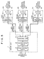
- Fig. 5 is a block diagram showing the structure of a second embodiment of the present invention.
- the difference between the second embodiment and the first embodiment is in that the powers of three first-intermediate frequency signals sent to an indoor unit 1 are combined directly by a combining unit 10.
- First frequency converters 6a, 6b, and 6c in outdoor units 2a, 2b, and 2c convert reception frequency signals into intermediate frequency signals as input signals to a demodulating circuit 8.
- the powers of the first intermediate frequency signals with the same frequency can be combined.
- the first frequency converters 6a, 6b, and 6c in the outdoor units 2a, 2b, and 2c should vary the deviation amounts of frequencies corresponding to radio frequencies used in the individual fan-shaped divided zones and should output coincident frequency signal to a combining unit 10.
- the operation of the indoor unit 1 shown in Fig. 5 is restricted. Consequently, the structure shown in Fig. 5 is limited to the case that the radio frequencies for use are fixed and they are not varied during the operation.
- the hardware scale can be remarkably reduced.
Landscapes
- Engineering & Computer Science (AREA)
- Computer Networks & Wireless Communication (AREA)
- Signal Processing (AREA)
- Mobile Radio Communication Systems (AREA)
- Time-Division Multiplex Systems (AREA)
Applications Claiming Priority (3)
| Application Number | Priority Date | Filing Date | Title |
|---|---|---|---|
| JP234086/95 | 1995-09-12 | ||
| JP23408695 | 1995-09-12 | ||
| JP7234086A JPH0983473A (ja) | 1995-09-12 | 1995-09-12 | Tdma通信方法及びtdma受信装置 |
Publications (2)
| Publication Number | Publication Date |
|---|---|
| EP0762670A2 true EP0762670A2 (de) | 1997-03-12 |
| EP0762670A3 EP0762670A3 (de) | 2000-06-21 |
Family
ID=16965401
Family Applications (1)
| Application Number | Title | Priority Date | Filing Date |
|---|---|---|---|
| EP96114632A Withdrawn EP0762670A3 (de) | 1995-09-12 | 1996-09-12 | TDMA Kommunikationsverfahren für Basisstation die für verschiedene Zonen verschiedene Frequenzen anwendet und Empfänger dafür |
Country Status (3)
| Country | Link |
|---|---|
| US (1) | US6160800A (de) |
| EP (1) | EP0762670A3 (de) |
| JP (1) | JPH0983473A (de) |
Cited By (2)
| Publication number | Priority date | Publication date | Assignee | Title |
|---|---|---|---|---|
| KR19990072537A (ko) * | 1998-02-13 | 1999-09-27 | 루센트 테크놀러지스 인크 | 무선원격통신시스템및방법 |
| EP0936754A3 (de) * | 1998-02-13 | 2001-07-25 | Lucent Technologies Inc. | Architektur für schnurloses Telekommunikationssystem zur Unterstützung von Empfangsdiversity |
Families Citing this family (8)
| Publication number | Priority date | Publication date | Assignee | Title |
|---|---|---|---|---|
| FI112992B (fi) * | 1999-12-15 | 2004-02-13 | Nokia Corp | Menetelmä ja järjestelmä useiden käyttäjien lomittamiseksi TDMA-järjestelmän tietoliikennekanaville |
| US7123649B1 (en) * | 2000-11-03 | 2006-10-17 | Peter Smith | Outdoor unit programming system |
| US6731946B1 (en) * | 2000-11-22 | 2004-05-04 | Ensemble Communications | System and method for timing detector measurements in a wireless communication system |
| KR100443339B1 (ko) * | 2001-10-25 | 2004-08-09 | 주식회사 휴텍이일 | 이동통신기지국의 고주파분산 및 원격감시 제어장치 |
| US7773614B1 (en) | 2001-12-05 | 2010-08-10 | Adaptix, Inc. | Wireless communication subsystem with a digital interface |
| CN102509852A (zh) * | 2011-09-28 | 2012-06-20 | 华为技术有限公司 | 天线装置 |
| US11637612B2 (en) | 2015-08-25 | 2023-04-25 | Cellium Technologies, Ltd. | Macro-diversity using hybrid transmissions via twisted pairs |
| US10177832B2 (en) * | 2015-08-25 | 2019-01-08 | Cellium Technologies, Ltd. | Using a coaxial cable for distributing MIMO signals in-house |
Family Cites Families (18)
| Publication number | Priority date | Publication date | Assignee | Title |
|---|---|---|---|---|
| DE1591336A1 (de) * | 1966-10-22 | 1970-12-23 | ||
| DE3120240A1 (de) * | 1981-05-21 | 1982-12-09 | Protektorwerk Florenz Maisch Gmbh & Co Kg, 7560 Gaggenau | Verwendung von putzprofilleisten zum herstellen ebener unterputze mit vorbestimmter mindestputzdicke und putzprofilleiste fuer diesen zweck |
| DE3121146A1 (de) * | 1981-05-27 | 1983-01-05 | Siemens AG, 1000 Berlin und 8000 München | Digitales funksystem |
| JPS62155628A (ja) * | 1985-12-27 | 1987-07-10 | Mitsubishi Electric Corp | 時分割多重化通信設備 |
| JPS6457835A (en) * | 1987-08-28 | 1989-03-06 | Nippon Telegraph & Telephone | Time division mobile multiplex communication system |
| JPH01300634A (ja) * | 1988-05-30 | 1989-12-05 | Nippon Telegr & Teleph Corp <Ntt> | 移動通信におけるセクタゾーン制御方式 |
| JPH0298238A (ja) * | 1988-10-04 | 1990-04-10 | Nec Corp | 無線通信装置 |
| JPH03143123A (ja) * | 1989-10-30 | 1991-06-18 | Nippon Telegr & Teleph Corp <Ntt> | 移動通信システムのランダムアクセス方法 |
| JP2623882B2 (ja) * | 1990-01-08 | 1997-06-25 | 日本電気株式会社 | セクタ制御方法 |
| JP3093243B2 (ja) * | 1990-07-12 | 2000-10-03 | 株式会社東芝 | 移動無線通信システム |
| US5203025A (en) * | 1990-11-09 | 1993-04-13 | Kovatel Communications, Ltd. | Selection circuit in a space diversity reception system for a mobile receiver |
| US5410588A (en) * | 1991-04-03 | 1995-04-25 | Kabushiki Kaisha Toshiba | Mobile radio communications system having a supervising radio transmitting station for transmitting a reference synchronizing signal to a first and second base stations via a radio link |
| JPH05130158A (ja) * | 1991-11-08 | 1993-05-25 | Sony Corp | 送受信装置 |
| GB2268027B (en) * | 1992-06-20 | 1996-08-21 | Motorola Inc | Trunking radio system with frequency diversity |
| FI96554C (fi) * | 1993-02-05 | 1996-07-10 | Nokia Mobile Phones Ltd | Aikajakoinen solukkoradiopuhelinjärjestelmä ja radiopuhelin sitä varten |
| US5546383A (en) * | 1993-09-30 | 1996-08-13 | Cooley; David M. | Modularly clustered radiotelephone system |
| JP2576388B2 (ja) * | 1993-11-08 | 1997-01-29 | 日本電気株式会社 | 基地局送受信装置 |
| US5574966A (en) * | 1994-12-30 | 1996-11-12 | Lucent Technologies Inc. | Wireless base station architecture |
-
1995
- 1995-09-12 JP JP7234086A patent/JPH0983473A/ja active Pending
-
1996
- 1996-09-09 US US08/711,124 patent/US6160800A/en not_active Expired - Fee Related
- 1996-09-12 EP EP96114632A patent/EP0762670A3/de not_active Withdrawn
Cited By (5)
| Publication number | Priority date | Publication date | Assignee | Title |
|---|---|---|---|---|
| KR19990072537A (ko) * | 1998-02-13 | 1999-09-27 | 루센트 테크놀러지스 인크 | 무선원격통신시스템및방법 |
| EP0936754A3 (de) * | 1998-02-13 | 2001-07-25 | Lucent Technologies Inc. | Architektur für schnurloses Telekommunikationssystem zur Unterstützung von Empfangsdiversity |
| KR100350542B1 (ko) * | 1998-02-13 | 2002-08-28 | 루센트 테크놀러지스 인크 | 수신 다이버시티를 지원하는 무선 원격 통신 장치 및 방법 |
| US6539239B1 (en) | 1998-02-13 | 2003-03-25 | Lucent Technologies, Inc. | Wireless telecommunications system architecture supporting receive diversity |
| CN100365952C (zh) * | 1998-02-13 | 2008-01-30 | 朗迅科技公司 | 支持接收分集的无线电信系统结构 |
Also Published As
| Publication number | Publication date |
|---|---|
| EP0762670A3 (de) | 2000-06-21 |
| US6160800A (en) | 2000-12-12 |
| JPH0983473A (ja) | 1997-03-28 |
Similar Documents
| Publication | Publication Date | Title |
|---|---|---|
| US5329548A (en) | Base station for a frequency hopping TDMA radio communication system | |
| US6192216B1 (en) | Remotely controlled gain control of transceiver used to inter-connect wireless telephones to a broadband network | |
| AU663604B2 (en) | Multiple cavity tuning of a transmitter output in a communication system | |
| EP1080594B1 (de) | Verbesserte zentral angeordnete einrichtung für ein drahtloses fernsprechsystem und entsprechendes verfahren | |
| US6374124B1 (en) | Dynamic reallocation of transceivers used to interconnect wireless telephones to a broadband network | |
| US5584057A (en) | Use of diversity transmission to relax adjacent channel requirements in mobile telephone systems | |
| US6223021B1 (en) | Signal filtering in a transceiver for a wireless telephone system | |
| EP1037411A2 (de) | Verstärkungsausgleich für ein fiberoptisches Verteilungsnetzwerk | |
| EP0468688B1 (de) | Verfahren und Vorrichtung zur drahtlosen Kommunikation zwischen entfernten Lagen | |
| US6430421B1 (en) | Adaptive radio system | |
| US6160800A (en) | TDMA communicating method and TDMA receiving apparatus | |
| US5903592A (en) | Radio transmission system | |
| EP0715786B1 (de) | Basisstationsanlage unter verwendung von diversityempfang | |
| JPH11136735A (ja) | 無線通信システム | |
| GB2290006A (en) | Base station transmitter control | |
| JP2586263B2 (ja) | ダイバーシチ送受信方式 | |
| KR100272972B1 (ko) | 중계장치를이용한무선통신시스템용무선통신처리방법 | |
| JP2503869B2 (ja) | 無線通信方式 | |
| AU734723C (en) | A data transmission method and base station for a TDMA radio system | |
| JP3244256B2 (ja) | 移動通信エリア拡張装置 | |
| CA2157495A1 (en) | Radio repeater | |
| JPH0470015A (ja) | 制御チャネル構成方法 | |
| KR20010018843A (ko) | 이기종 이동통신 시스템의 서비스 방법 및 그 장치 | |
| JPS58178640A (ja) | 衛星通信方式 | |
| HK1011157B (en) | A base station for a frequency hopping tdma radio communication system |
Legal Events
| Date | Code | Title | Description |
|---|---|---|---|
| PUAI | Public reference made under article 153(3) epc to a published international application that has entered the european phase |
Free format text: ORIGINAL CODE: 0009012 |
|
| AK | Designated contracting states |
Kind code of ref document: A2 Designated state(s): DE FR GB |
|
| PUAL | Search report despatched |
Free format text: ORIGINAL CODE: 0009013 |
|
| AK | Designated contracting states |
Kind code of ref document: A3 Designated state(s): DE FR GB |
|
| 17P | Request for examination filed |
Effective date: 20000517 |
|
| STAA | Information on the status of an ep patent application or granted ep patent |
Free format text: STATUS: THE APPLICATION HAS BEEN WITHDRAWN |
|
| 18W | Application withdrawn |
Effective date: 20031020 |