EP0762749A2 - Système de traitement vidéo pour un système de visualisation vidéo - Google Patents
Système de traitement vidéo pour un système de visualisation vidéo Download PDFInfo
- Publication number
- EP0762749A2 EP0762749A2 EP96113472A EP96113472A EP0762749A2 EP 0762749 A2 EP0762749 A2 EP 0762749A2 EP 96113472 A EP96113472 A EP 96113472A EP 96113472 A EP96113472 A EP 96113472A EP 0762749 A2 EP0762749 A2 EP 0762749A2
- Authority
- EP
- European Patent Office
- Prior art keywords
- video
- digital input
- scaling
- field
- data
- Prior art date
- Legal status (The legal status is an assumption and is not a legal conclusion. Google has not performed a legal analysis and makes no representation as to the accuracy of the status listed.)
- Ceased
Links
Images


Classifications
-
- H—ELECTRICITY
- H04—ELECTRIC COMMUNICATION TECHNIQUE
- H04N—PICTORIAL COMMUNICATION, e.g. TELEVISION
- H04N9/00—Details of colour television systems
- H04N9/12—Picture reproducers
- H04N9/30—Picture reproducers using solid-state colour display devices
-
- H—ELECTRICITY
- H04—ELECTRIC COMMUNICATION TECHNIQUE
- H04N—PICTORIAL COMMUNICATION, e.g. TELEVISION
- H04N7/00—Television systems
- H04N7/01—Conversion of standards, e.g. involving analogue television standards or digital television standards processed at pixel level
-
- H—ELECTRICITY
- H04—ELECTRIC COMMUNICATION TECHNIQUE
- H04N—PICTORIAL COMMUNICATION, e.g. TELEVISION
- H04N7/00—Television systems
- H04N7/01—Conversion of standards, e.g. involving analogue television standards or digital television standards processed at pixel level
- H04N7/0117—Conversion of standards, e.g. involving analogue television standards or digital television standards processed at pixel level involving conversion of the spatial resolution of the incoming video signal
- H04N7/012—Conversion between an interlaced and a progressive signal
-
- H—ELECTRICITY
- H04—ELECTRIC COMMUNICATION TECHNIQUE
- H04N—PICTORIAL COMMUNICATION, e.g. TELEVISION
- H04N7/00—Television systems
- H04N7/01—Conversion of standards, e.g. involving analogue television standards or digital television standards processed at pixel level
- H04N7/0117—Conversion of standards, e.g. involving analogue television standards or digital television standards processed at pixel level involving conversion of the spatial resolution of the incoming video signal
- H04N7/0122—Conversion of standards, e.g. involving analogue television standards or digital television standards processed at pixel level involving conversion of the spatial resolution of the incoming video signal the input and the output signals having different aspect ratios
Definitions
- This invention relates to display systems, more particularly to display systems that use digital processing of the video signals.
- CTR cathode ray tube
- spatial light modulators which normally consist of an array of individually selectable elements over addressing circuitry that is addressed to make the selection.
- the addressing circuitry of these modulators is typically organized in rows and columns, making the selection of all of the odd-numbered lines or the even-numbered lines awkward, slow and costly.
- Another adaptation that must be made is the ability of the system to display different formats of incoming data.
- the incoming data is typically digitized at a rate equal to the pixels per line dimension in these types of systems.
- the 640 pixels per line would be digitized at 640 samples per line.
- the processor therefore, must be able to adjust not only for displaying more than one format on a fixed number of elements in the array, but to have a sampling rate that is compatible with any given format.
- One aspect of the invention is a processing system for video data.
- the system receives data and formats or samples it at a common rate. This allows the system to format and process the data for different input formats.
- the system relies upon only one processor to perform functions of motion detection, motion adaptive scan conversion, horizontal and vertical scaling and sharpness control.
- Figure 1 shows an overall system architecture 10 for video processing using only one scan-line video processor (SVP) 12.
- SVP scan-line video processor
- the incoming luminance signal Y undergoes two field delays at field DLs 14 and 16. These field delays are used to allow access to data from the most previous and next most previous fields. For example, if the incoming field at Y were said to be field 2, after field DL 14, at point A, the field would be the most previous field, field 1. After field DL 16, at point B, the field would be the next most previous field, field 0. Field 2 and field 0 have the same numbered lines in them, but are from different video frames. This additional data will be used in the interpolation of data as will be discussed with reference to Figure 2.
- the input signal Y is typically already in digital form when it reaches the processor 12. This could result from digitization of an analog signal, as would happen with current broadcast video signals. Additionally, the signal could originate as a digital signal.
- the system of Figure 1 will need to be able to use the data of any format on the spatial light modulator or modulators that form the images for display.
- Figures 5 and 6 will discuss specific techniques for scaling the common rate signal to fit multiple formats. All of these functions may be performed by scan line video processors. It is an advantage of this invention in that it allows all of these functions to be performed by the same processor, thereby reducing the amount of hardware and the system cost.
- Figure 2 shows one possible process for motion adaptive progressive scan conversion. This process is used to interpolate the "missing field" from an interlace data field, while accounting for motion signals between the fields.
- the mixing circuit 30 uses data from the following lines of data, where field 3 is the incoming field: the most previous field, field 2, from the field DL 22; the adjacent line in the next most previous field, field 1, from horizontal DL 24 and field DL 26; and the motion signal k, from the top data path.
- the top data path initially uses a comparison between the incoming signal Y, field 3, and the adjacent line from field 1, which has like-numbered lines. An arithmetic or other circuit finds the difference between these at 32.
- the resulting difference is passed through a horizontal lowpass filter HLPF1 at 34, and the absolute value is found at ABS 36.
- a non-linear function NL 38 is applied.
- the nonlinear function performs thresholding to eliminate small difference signal values due to noise. It also reduces the resolution of the difference signal to 4 bits.
- a comparator 44 determines the maximum of several values: data from field 0, out of field DL 40; data from the adjacent lines to the line undergoing processing, out of horizontal delays 42a, 42b, and 42c; and the resulting 4-bit signal from the nonlinear function 32.
- This maximum value is then filtered both vertically and horizontally at VLPF1 46 and HLPF2 48, respectively.
- the nonlinear function 50 is similar to that of 38 in that it reduces signal noise.
- the resulting motion signal, k is then passed to the mixing circuit 30 and used to determine the interpolated output.
- Figures 3a-3d show graphical representation of four different formats.
- Figure 3a shows a graphical representation of the scaling and processing necessary for NTSC input.
- the input active pixel area is 720 samples wide and 480 lines long.
- the rate of 720 samples per line is an example of the common rate discussed earlier. It must be sampled down from 720 to 640 samples per line in order to maintain a 4:3 square pixel aspect ratio.
- the selection of 720 samples makes this an "integer" scaling process of 9:8, rather than any kind of fractional scaling process. This conversion does not require any vertical scaling.
- Figure 3a shows that device used in this example has a dimension of 848 x 480. This allows display of the NTSC standard of 640 x 480.
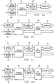
- Figure 4a shows the process flow for NTSC signals in block diagram form.
- the process blocks of proscan interpolation 54, motion detection 52, and sharpness control 56 remain the same in each embodiment shown in Figure 4.
- the luminance signal, Y undergoes motion detection 52 before proscan interpolation 56, then is scaled horizontally at 58 and finally sharpened at 56.
- the chrominance signal, C undergoes horizontal scaling first at 60, the proscan interpolation at 54.
- Figure 3b shows a similar conversion for a format referred to as NTSC Letterbox.
- the input pixel active area is still 720 samples wide, but has a reduced length of 360 lines, instead of the standard 480.
- the other 120 lines are black borders, of 60 lines per side.
- This type of format can be converted to 848 x 480 by doing both vertical and horizontal scaling.
- This format has a 16:9 aspect ratio, which will require the image be scaled horizontally from 720 samples to 848 elements, and vertically from 360 lines to 480 lines of elements.
- the scaling factors are 5:6 horizontally (720/848), and 3:4 vertically (360/480).
- the horizontal black borders seen in the input are cropped from the final image.
- Figure 4b shows the processing functions for NTSC Letterbox.
- the luminance signal again undergoes motion detection 52, proscan interpolation 54, and 5:6 horizontal scaling at 62.
- the chrominance signal undergoes 5:6 horizontal scaling at 64, proscan conversion at 54, and then is used in conjunction with the luminance signal at the vertical scaling process 68. Finally, the luminance signal is sharpened at 56.
- the same type of processing can be used with PAL format signals.
- the incoming data has a dimension of 720 x 576. However, for this display application only 548 out of 576 lines are used. It will be scaled horizontally down by a factor 9:8 and scaled down vertically by 8:7.
- the block diagram of the processes is shown in Figure 4c. The same processes are in place, with the addition of 8:7 vertical scaling of both chrominance and luminance at 70.
- PALplus is similar to NTSC Letterbox in that contains video information for a 16:9 aspect ratio. However, the information required to produce a 16:9 picture has been horizontally squeezed to fit within a 4:3 aspect ratio. As can be seen in Figure 3d, the image will have to be scaled horizontally and vertically, and some of the columns will have to be cropped. Horizontally, the data must be scaled by a factor of 5:6, to get from 720 to 864.
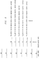
- FIG. 1 Shown is an example for discussion purposes of the vertical scaling coefficients for 3:4 scaling.
- 3:4 scaling process three lines are used to create 4.
- lines X 2 , X 3 , and X 4 are used to create Y0, Y1, Y2, and Y3.
- the output lines Y0 - Y4 are found by applying the dot product of the coefficients shown with the lines of input data X0 - X7.
- [A B] ⁇ [X Y] AX + BY.
- the subscript numbers designate from which sub-filter the coefficients were produced.
- Y0 1 has coefficients -3/512, 13/512, 492/512, 13/512, and -3/512. These were produced from sub-filter 1.
- the filters are applied in the order 1, 2, 3, 0, 1...etc. Note also that at Y4, the coefficients begin to repeat as the sub-filter used is repeated.
- the filters used here are finite impulse response (FIR) filters, which are optimized for the trade off between picture quality and the cost of implementation.
- FIR finite impulse response
- FIG. 6 A graphical representation of such a process is shown in Figure 6.
- This system uses 2608 instructions to perform all of the above functions, which is approximately 95 % of the available 2730 instruction space.
- the advanced FIR filters were not previously usable in the older SVPs because of the amount of instruction space they consumed.
- scaling involves using as many scaling factors as possible, here the scaling factors have been limited without sacrificing any functionality of the system.
- this system has the capability of being adaptable to new and different formats.
- PALplus which has not been previously considered was used easily in this system. This is due to the inherent flexibility of the system.
Landscapes
- Engineering & Computer Science (AREA)
- Multimedia (AREA)
- Signal Processing (AREA)
- Computer Graphics (AREA)
- Television Systems (AREA)
- Controls And Circuits For Display Device (AREA)
Applications Claiming Priority (2)
| Application Number | Priority Date | Filing Date | Title |
|---|---|---|---|
| US275895P | 1995-08-24 | 1995-08-24 | |
| US2758 | 1995-08-24 |
Publications (2)
| Publication Number | Publication Date |
|---|---|
| EP0762749A2 true EP0762749A2 (fr) | 1997-03-12 |
| EP0762749A3 EP0762749A3 (fr) | 1997-05-07 |
Family
ID=21702360
Family Applications (1)
| Application Number | Title | Priority Date | Filing Date |
|---|---|---|---|
| EP96113472A Ceased EP0762749A3 (fr) | 1995-08-24 | 1996-08-22 | Système de traitement vidéo pour un système de visualisation vidéo |
Country Status (5)
| Country | Link |
|---|---|
| EP (1) | EP0762749A3 (fr) |
| JP (1) | JPH09182031A (fr) |
| KR (1) | KR100426996B1 (fr) |
| CA (1) | CA2183797A1 (fr) |
| TW (1) | TW447213B (fr) |
Cited By (1)
| Publication number | Priority date | Publication date | Assignee | Title |
|---|---|---|---|---|
| US5806611A (en) * | 1995-05-31 | 1998-09-15 | Shell Oil Company | Device for controlling weight on bit of a drilling assembly |
Family Cites Families (3)
| Publication number | Priority date | Publication date | Assignee | Title |
|---|---|---|---|---|
| JP2861213B2 (ja) * | 1990-03-13 | 1999-02-24 | ソニー株式会社 | 画像表示装置 |
| US5489952A (en) * | 1993-07-14 | 1996-02-06 | Texas Instruments Incorporated | Method and device for multi-format television |
| US5452024A (en) * | 1993-11-01 | 1995-09-19 | Texas Instruments Incorporated | DMD display system |
-
1996
- 1996-08-21 CA CA002183797A patent/CA2183797A1/fr not_active Abandoned
- 1996-08-22 EP EP96113472A patent/EP0762749A3/fr not_active Ceased
- 1996-08-23 JP JP8222741A patent/JPH09182031A/ja active Pending
- 1996-08-24 KR KR1019960035351A patent/KR100426996B1/ko not_active Expired - Lifetime
- 1996-09-16 TW TW085111272A patent/TW447213B/zh not_active IP Right Cessation
Cited By (1)
| Publication number | Priority date | Publication date | Assignee | Title |
|---|---|---|---|---|
| US5806611A (en) * | 1995-05-31 | 1998-09-15 | Shell Oil Company | Device for controlling weight on bit of a drilling assembly |
Also Published As
| Publication number | Publication date |
|---|---|
| EP0762749A3 (fr) | 1997-05-07 |
| TW447213B (en) | 2001-07-21 |
| CA2183797A1 (fr) | 1997-02-25 |
| JPH09182031A (ja) | 1997-07-11 |
| KR100426996B1 (ko) | 2004-11-02 |
| KR970014303A (ko) | 1997-03-29 |
Similar Documents
| Publication | Publication Date | Title |
|---|---|---|
| US6281873B1 (en) | Video line rate vertical scaler | |
| US5570135A (en) | Method and device for multi-format television | |
| JP2673386B2 (ja) | 映像表示装置 | |
| US5574572A (en) | Video scaling method and device | |
| US5671298A (en) | Image scaling using cubic filters | |
| US5621470A (en) | Interpixel and interframe interpolation of television pictures with conversion from interlaced to progressive scanning | |
| US5455628A (en) | Converter to convert a computer graphics signal to an interlaced video signal | |
| EP0647070A2 (fr) | Améliorations relatives à la télévision numérique | |
| US6320619B1 (en) | Flicker filter circuit | |
| US5159438A (en) | Aspect ratio conversion of television display | |
| WO1998020670A2 (fr) | Procede et dispositif de conversion de signaux infographiques en signaux video tv avec changement d'echelles verticale et horizontale sans utilisation de tampon de trame | |
| US5864367A (en) | Video processing system with scan-line video processor | |
| CA1230669A (fr) | Systeme d'affichage a balayage progressif pour la television | |
| TW511073B (en) | A method and apparatus in a computer system to generate a downscaled video image for display on a television system | |
| US5838385A (en) | Sampling analog video signal for secondary images | |
| US5381182A (en) | Flat panel image reconstruction interface for producing a non-interlaced video signal | |
| US5668602A (en) | Real-time television image pixel multiplication methods and apparatus | |
| US5483474A (en) | D-dimensional, fractional bandwidth signal processing apparatus | |
| US6128539A (en) | Method and apparatus for forming image scaling filters | |
| EP0762749A2 (fr) | Système de traitement vidéo pour un système de visualisation vidéo | |
| US7701519B2 (en) | Display system and signal processing using diamond-shaped DMDs | |
| US20040239819A1 (en) | Display system and signal processing using diamond-shaped DMDs | |
| US6320620B1 (en) | Low cost progressive scan television with special features | |
| KR100426999B1 (ko) | 보조화상용아날로그비디오신호를샘플링하는방법및장치 | |
| EP0762737A2 (fr) | Améliorations dans les systèmes d'affichage |
Legal Events
| Date | Code | Title | Description |
|---|---|---|---|
| PUAI | Public reference made under article 153(3) epc to a published international application that has entered the european phase |
Free format text: ORIGINAL CODE: 0009012 |
|
| AK | Designated contracting states |
Kind code of ref document: A2 Designated state(s): DE FR GB IT NL |
|
| PUAL | Search report despatched |
Free format text: ORIGINAL CODE: 0009013 |
|
| AK | Designated contracting states |
Kind code of ref document: A3 Designated state(s): DE FR GB IT NL |
|
| 17P | Request for examination filed |
Effective date: 19970709 |
|
| 17Q | First examination report despatched |
Effective date: 19990517 |
|
| STAA | Information on the status of an ep patent application or granted ep patent |
Free format text: STATUS: THE APPLICATION HAS BEEN REFUSED |
|
| 18R | Application refused |
Effective date: 20001102 |