EP0762985B1 - Vorrichtung zum Transport von Gegenständen - Google Patents
Vorrichtung zum Transport von Gegenständen Download PDFInfo
- Publication number
- EP0762985B1 EP0762985B1 EP95925496A EP95925496A EP0762985B1 EP 0762985 B1 EP0762985 B1 EP 0762985B1 EP 95925496 A EP95925496 A EP 95925496A EP 95925496 A EP95925496 A EP 95925496A EP 0762985 B1 EP0762985 B1 EP 0762985B1
- Authority
- EP
- European Patent Office
- Prior art keywords
- monorail
- track
- carriage
- carriages
- bearing assembly
- Prior art date
- Legal status (The legal status is an assumption and is not a legal conclusion. Google has not performed a legal analysis and makes no representation as to the accuracy of the status listed.)
- Expired - Lifetime
Links
- 230000009471 action Effects 0.000 claims description 4
- 230000007246 mechanism Effects 0.000 description 10
- 230000006835 compression Effects 0.000 description 4
- 238000007906 compression Methods 0.000 description 4
- JOYRKODLDBILNP-UHFFFAOYSA-N Ethyl urethane Chemical compound CCOC(N)=O JOYRKODLDBILNP-UHFFFAOYSA-N 0.000 description 3
- 229910000831 Steel Inorganic materials 0.000 description 3
- 230000000712 assembly Effects 0.000 description 3
- 238000000429 assembly Methods 0.000 description 3
- 230000008901 benefit Effects 0.000 description 3
- 229910052751 metal Inorganic materials 0.000 description 3
- 239000002184 metal Substances 0.000 description 3
- 239000010959 steel Substances 0.000 description 3
- 238000013459 approach Methods 0.000 description 2
- 238000010276 construction Methods 0.000 description 2
- 230000000694 effects Effects 0.000 description 2
- 238000001125 extrusion Methods 0.000 description 2
- 230000006698 induction Effects 0.000 description 2
- 239000000463 material Substances 0.000 description 2
- 238000000034 method Methods 0.000 description 2
- 230000004048 modification Effects 0.000 description 2
- 238000012986 modification Methods 0.000 description 2
- 230000008439 repair process Effects 0.000 description 2
- 238000003466 welding Methods 0.000 description 2
- 239000004411 aluminium Substances 0.000 description 1
- 229910052782 aluminium Inorganic materials 0.000 description 1
- XAGFODPZIPBFFR-UHFFFAOYSA-N aluminium Chemical compound [Al] XAGFODPZIPBFFR-UHFFFAOYSA-N 0.000 description 1
- 230000033228 biological regulation Effects 0.000 description 1
- 230000008859 change Effects 0.000 description 1
- 239000003638 chemical reducing agent Substances 0.000 description 1
- 229910003460 diamond Inorganic materials 0.000 description 1
- 239000010432 diamond Substances 0.000 description 1
- 230000009977 dual effect Effects 0.000 description 1
- 239000013536 elastomeric material Substances 0.000 description 1
- 239000000945 filler Substances 0.000 description 1
- 230000003993 interaction Effects 0.000 description 1
- 235000000396 iron Nutrition 0.000 description 1
- 230000003137 locomotive effect Effects 0.000 description 1
- 238000012423 maintenance Methods 0.000 description 1
- 230000013011 mating Effects 0.000 description 1
- 150000002739 metals Chemical class 0.000 description 1
- 230000009467 reduction Effects 0.000 description 1
- 230000002441 reversible effect Effects 0.000 description 1
- 238000012552 review Methods 0.000 description 1
- 230000000630 rising effect Effects 0.000 description 1
- 239000007787 solid Substances 0.000 description 1
- 125000006850 spacer group Chemical group 0.000 description 1
- 238000006467 substitution reaction Methods 0.000 description 1
Images


Classifications
-
- B—PERFORMING OPERATIONS; TRANSPORTING
- B65—CONVEYING; PACKING; STORING; HANDLING THIN OR FILAMENTARY MATERIAL
- B65G—TRANSPORT OR STORAGE DEVICES, e.g. CONVEYORS FOR LOADING OR TIPPING, SHOP CONVEYOR SYSTEMS OR PNEUMATIC TUBE CONVEYORS
- B65G23/00—Driving gear for endless conveyors; Belt- or chain-tensioning arrangements
- B65G23/02—Belt- or chain-engaging elements
- B65G23/04—Drums, rollers, or wheels
- B65G23/10—Drums, rollers, or wheels arranged intermediate the ends of the conveyors
-
- B—PERFORMING OPERATIONS; TRANSPORTING
- B65—CONVEYING; PACKING; STORING; HANDLING THIN OR FILAMENTARY MATERIAL
- B65G—TRANSPORT OR STORAGE DEVICES, e.g. CONVEYORS FOR LOADING OR TIPPING, SHOP CONVEYOR SYSTEMS OR PNEUMATIC TUBE CONVEYORS
- B65G17/00—Conveyors having an endless traction element, e.g. a chain, transmitting movement to a continuous or substantially-continuous load-carrying surface or to a series of individual load-carriers; Endless-chain conveyors in which the chains form the load-carrying surface
- B65G17/30—Details; Auxiliary devices
- B65G17/32—Individual load-carriers
- B65G17/34—Individual load-carriers having flat surfaces, e.g. platforms, grids, forks
- B65G17/345—Individual load-carriers having flat surfaces, e.g. platforms, grids, forks the surfaces being equipped with a conveyor
-
- B—PERFORMING OPERATIONS; TRANSPORTING
- B65—CONVEYING; PACKING; STORING; HANDLING THIN OR FILAMENTARY MATERIAL
- B65G—TRANSPORT OR STORAGE DEVICES, e.g. CONVEYORS FOR LOADING OR TIPPING, SHOP CONVEYOR SYSTEMS OR PNEUMATIC TUBE CONVEYORS
- B65G23/00—Driving gear for endless conveyors; Belt- or chain-tensioning arrangements
- B65G23/22—Arrangements or mountings of driving motors
-
- B—PERFORMING OPERATIONS; TRANSPORTING
- B65—CONVEYING; PACKING; STORING; HANDLING THIN OR FILAMENTARY MATERIAL
- B65G—TRANSPORT OR STORAGE DEVICES, e.g. CONVEYORS FOR LOADING OR TIPPING, SHOP CONVEYOR SYSTEMS OR PNEUMATIC TUBE CONVEYORS
- B65G47/00—Article or material-handling devices associated with conveyors; Methods employing such devices
- B65G47/74—Feeding, transfer, or discharging devices of particular kinds or types
- B65G47/94—Devices for flexing or tilting travelling structures; Throw-off carriages
- B65G47/96—Devices for tilting links or platform
- B65G47/962—Devices for tilting links or platform tilting about an axis substantially parallel to the conveying direction
-
- B—PERFORMING OPERATIONS; TRANSPORTING
- B65—CONVEYING; PACKING; STORING; HANDLING THIN OR FILAMENTARY MATERIAL
- B65G—TRANSPORT OR STORAGE DEVICES, e.g. CONVEYORS FOR LOADING OR TIPPING, SHOP CONVEYOR SYSTEMS OR PNEUMATIC TUBE CONVEYORS
- B65G2201/00—Indexing codes relating to handling devices, e.g. conveyors, characterised by the type of product or load being conveyed or handled
- B65G2201/02—Articles
-
- B—PERFORMING OPERATIONS; TRANSPORTING
- B65—CONVEYING; PACKING; STORING; HANDLING THIN OR FILAMENTARY MATERIAL
- B65G—TRANSPORT OR STORAGE DEVICES, e.g. CONVEYORS FOR LOADING OR TIPPING, SHOP CONVEYOR SYSTEMS OR PNEUMATIC TUBE CONVEYORS
- B65G2207/00—Indexing codes relating to constructional details, configuration and additional features of a handling device, e.g. Conveyors
- B65G2207/18—Crossing conveyors
Definitions
- the present invention relates to an apparatus for transporting objects, especially to a slack control assembly for a track of such an apparatus, particularly an automatic sorting apparatus using tilting trays which receive items from input conveyors and deposit them into designated output chutes or bins under programmed control.
- Tilt tray sorters have been available for many years. Such systems are useful in sorting small packages for delivery to different regions, such as zip code areas. Under control of a computer or programmed logic controller, packages may be identified or coded as they enter the system, and then tracked for output at a chute or bin corresponding to the coded destination.
- the sorting system disclosed in U.S. Pat.No.4,712,965 drives linked carriages around a dual rail track by means of one or more drive carriages.
- the drive carriages contain motors which drive rollers which are pressed against a third rail by the weight of the motor.
- Tilting tray sorting systems are also shown in U.S. Pat. Nos.4,089,404; 5,018,928 and 4,982,828.
- the present invention provides an apparatus for transporting objects, including a track, a carriage for moving along the track and transporting the objects, the carriage including a frame, a first bearing assembly linked to the frame and for engaging a first side of the track, and a second bearing assembly movably mounted to the frame, characterised by
- the slack control assembly of the invention maintains the carriage in contact with the track, thus accommodating wear and any resulting clearance; consequent rattling , noise and vibration are substantially eliminated.
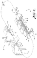
- Fig.1 shows an automatic sorting system 10 embodying the present invention.
- the sorting system 10 includes a monorail 12 and a line or train of carriages 14 mounted for travel along the monorail 12.
- the monorail forms a closed loop, and the carriages fill the monorail.
- the carriages 14 may be driven along the monorail in one direction by a drive mechanism 16.
- the carriages 14 travel through an input section 18 at which they are loaded with items, such as parcels to be delivered to addressee destinations, and then through output sections 20.
- the items are removed from the carriages by tilting mechanisms 22 which remove the items at an output chute corresponding to the item's destination.
- a return mechanism 24 which prepares the carriages to receive new items as they return to the input section 18, and a carriage tracking station 26 which positively locates a carriage carrying a particular item so that a controller (not shown) including a digital processor may cause the item to be sorted to the correct destination.
- the monorail 12 is supported by a plurality of support posts 30.
- a suspending bracket 32 extends from each post 30 and is attached, such as by welding, to the monorail 12, to hold the monorail 12 in a position spaced horizontally from the posts 30.
- the monorail 12 consists of a square steel extrusion held by the brackets 32 in a diamond configuration, that is, with opposing corners of the square cross section aligned vertically. Other metals or suitably strong materials may be utilized, and the beam may be hollow as shown or solid.
- An alternate embodiment of a monorail 34, designed for greater stability, is shown in Fig.6.
- a rectangular box beam 35 is attached to the posts 30 by a flanged support bracket 38.
- L-shaped extrusions or angle irons 36 are welded to the top and bottom surfaces of the box beam 35.
- the modified monorail 34 is an extended version of the square monorail 12.
- a removable section 40 of the monorail 12 is shown in Figs.4 and 5.
- a pair of special suspending brackets 42 are attached to the ends of the removable section 40 and the main monorail 12. Both of the brackets 42 are bolted to a slotted bracket 43 which is attached to the post 30. The brackets 42 slide into a slot 44 formed in the bracket 43, and are held in place by bolts 45 which pass through mating holes in the brackets 42 and 43. By removing the bolt 45 which attaches the removable section to the post 30, the removable section 40 can be slid out of the slot 44 in order to remove and replace carriages on the monorail 12. This procedure reduces down time in repairing carriages, since a carriage can be removed and replaced without any disassembly of the carriage itself.
- the train 14 of carriages is formed of a plurality of lower level carriages 50 and a plurality of upper level carriages 51.
- Both types of carriages 50 and 51 have a frame 52 in the shape of an elongate "C", which wraps around the monorail with the open side of the "C" facing the posts 30 and receiving the monorail 12 and support brackets 32.
- the frame 52 may be constructed of bent steel or another metal such as aluminium, or formed of any suitably strong material.
- Four axle bolts 54 shown in Figs.3 and 4 extend across the frame 52, two axles on either side of the monorail 12.
- rollers 55 are rotatably mounted on the axles 54 so as to engage the upper and lower sides of the monorail 12 with the corners of the monorail being received in the grooves of the rollers.
- the rollers 55 are provided with ball bearings (not shown) and preferably are made of urethane for noise reduction, but can be constructed of metal.
- Spacers 57 on either side of the rollers center the rollers within the frame 52.
- the axles and rollers are positioned so that the rollers snugly fit into the monorail 12 in a manner which permits free rotation of the rollers and smooth travel of the carriage along the monorail 12, without excess vibration.
- the train 14 of carriages 50 and 51 preferably alternates upper and lower level carriages and completely fills the looped monorail 12 with carriages.
- a bumper 58 as shown in Fig.4, may be fixed to one end of each carriage to cushion its contact with the adjacent carriage.
- the carriages are resiliently attached to one another.
- many advantages of the present invention can be incorporated in a monorail system which is not a closed loop. Also, the carriages might move in reversible directions, or the monorail could change elevation along its course or follow a serpentine path.
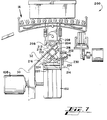
- the drive mechanism 16 is best shown in Figs.2 and 3. It provides a simple and reliable way to move the carriages around the monorail without complex chains, belts or gears as used in prior sorting mechanisms.
- a drive roller 102 preferably an inflated tire about two feet in diameter, is rotatably mounted on a shaft (not shown) passing through a shaft carrier 103 below the carriage frames 52.
- the shaft carrier 103 is pivotally connected to one of the posts 30 about horizontal pivot pins 105 aligned with a pivot axis parallel to the monorail 12.
- the shaft carrier 103 then extends beyond the post 30 into a speed reducer 107 associated with an electric motor 108 for driving the shaft.
- the drive connection between the drive mechanism 16 and the train 14 of carriages 50 and 51 is simply the frictional contact between the outer surface of the tire 102 and the lower surfaces of the carriages. Since the heavy motor 108 is cantilevered at the end of the shaft carrier 103 opposite the tire 102, the weight of the motor 108 urges the tire 102 against the carriage frame 52.
- the outer periphery of the tire 102 preferably consists of a high friction elastomeric material or tread.
- the drive mechanism 16 can be mounted at any location around the monorail loop, and several identical assemblies may be used with one monorail loop in order to provide redundancy and to even out the propulsion forces.
- a carriage for use in the sorting system 10 is shown in Figs.7-9 which has an automatic adjustment and gripping feature of a rail.
- the carriage 200 is designed to travel along a monorail 12, shown in the drawing as supported on a post 30 by a bracket 32.
- the carriage 200 has a frame 202 in the shape of an elongate "C", with the open side of the "C” facing the post 30 and receiving a monorail 12 and support brackets 32.
- the carriage 200 includes bearing assemblies for contracting the monorail 12 in the form of an upper carrying wheel cartridge 204 and a lower carrying wheel cartridge 206 within the frame 202, above and below the monorail 12, respectively.
- the right angles 212, 214 point toward the monorail.
- the wheel cartridges 204, 206 include feet 208, 210 extending from right angles 212, 214, respectively.
- the feet 208 on the upper carrying wheel cartridge 204 are fixed to the upper surface of the frame 202 by welding, bolts, or other suitable attachments.
- the lower carrying wheel cartridge 206 includes a unique height adjustment feature, described below, and extends between retaining tabs 216, two each of which are located on the back and font of the frame 202.
- a plurality of wheels 218 are mounted for rotation on adjacent sides of the right angles 212, 214.
- the wheels 218 are preferably urethane. As can best be seen in Fig.7, these wheels 218 are arranged to engage the flat surfaces of the square monorail 12.
- the ability to adjust the height of the lower carrying wheel cartridge 206 provides an automatic gap adjustment feature such that the wheels 218 engage the monorail 12 with pressure.
- the gap adjustment feature biases the wheels 218 against the monorail 12, and allows the carriage 200 to be used on a variety of different sized and shaped monorails.
- the main advantage of the automatic adjustment feature is that urethane rollers used in the past have worn over time and created clearance between the rail and the wheels. This clearance can cause a corresponding rattling noise or vibration. By providing the adjustment feature, the wheels 218 remain against the surface of the rail despite changes in the diameter of the wheels.
- the lower carrying wheel cartridge 206 is suspended on two cylinders 220, 222.
- the cylinders 220, 222 preferably extend transversely under the back and front ends of the lower carrying wheel cartridge 206, so that the cartridge may remain stable.
- Pins 224, 226 extend eccentrically out of both ends of the cylinders 220, 222, respectively, and are fixed to the cylinders such that rotation of the pins causes a corresponding rotation of the cylinders.
- the pins 224, 226 are mounted for free rotation within holes on opposite sides of the frame 202.
- Lever arms 230, 232 are fixed to the pins 224, 226 at ends which extend out of the side of the frame 202 opposite the post 30.
- a slack control device in the form of a compression spring 234 extends between the two lever arms 230, 232 and biases the two arms away from one another.
- the spring 234 may be any mechanical or electromechanical device that can offer a compression force including but not limited to hydraulic cylinders, electrostatic cylinders, magnetic devices, and steel recoil springs.
- the cylinders 220, 222 serve as cams and present camming surfaces on their outer diameters for engaging the feet 210 on the lower carrying wheel cartridge 206.
- the eccentric mounting of the pins 224, 226 relative to the cylinders 220, 222 causes the distance between the camming surface for each of the cylinders and the corresponding pin to increase or decrease, depending upon which portion of the surface is presented to the feet 210.
- the feet 210, and therefore the wheel cartridge 206 moves upward, or away from the respective pin 224, 226.
- the lower carrying wheel cartridge 206 moves downward, or closer to the pins 224, 226. It can be appreciated that rotating the pins 224, 226 varies the height of the lower carrying wheel cartridge 206, or either end of the cartridge so that the cartridge may snugly engage the monorail regardless of small changes in the dimensions of the wheels 218.
- the camming surfaces of the two cylinders 220, 222 are set such that for a normal or average size of the monorail 12, the camming surfaces of the cylinders engage the feet 210 at some point between A and B on the camming surfaces, so that adjustments both up and down in the height of the lower carrying wheel cartridge 206 are within the range of movement of the spring.
- the normal point of contact for the cylinder 220 is the point C and the normal point of contact for the cylinder 222 is the point D.
- Contact with the point B represents the minimum "camming action" for the cylinder.
- the variance in size of the monorail 12 will not exceed the distance determined by the camming surfaces of the cylinders 220, 222 reaching the points A and B. It can be appreciated that the cartridge 200 with the adjustment feature may fit without modification any rail having right-angle contact surfaces along the top and bottom sides and not exceeding the distance.
- the compression spring 234 by forcing the two lever arms 230, 232 apart, biases the point of contact of the camming surfaces on the cylinders 220, 222 with the feet 210 toward the point A on each of the cylinders.
- the compression spring 234 biases the lower carrying wheel cartridge 206 toward the upper carrying wheel cartridge 204, having the effect of closing any gaps that exist between the monorail 12 and the wheels 218, and biasing the lower wheels 218 against the bottom of the monorail, allowing for smooth and constant contact of the wheels 218 with the monorail 12.
- each of the pins 224, 226 is free to rotate independently, each end of the lower carrying wheel cartridge 206 adapts independently to fit against the monorail 12.
- a relatively constant force spring is used between the two lever arms 230, 232. It is to be understood that the camming surfaces on the two cylinders 220, 222 can be reversed and a tension spring may be used.
- the automatic gap adjustment feature of the present embodiment can be incorporated into a suspended monorail system, preferably by turning the frame 202 over so that the gap adjustment is along the top of the rail. Furthermore, the gap adjustment feature could be added to each side of the rail.
Landscapes
- Engineering & Computer Science (AREA)
- Mechanical Engineering (AREA)
- Discharge Of Articles From Conveyors (AREA)
- Control And Other Processes For Unpacking Of Materials (AREA)
- Sorting Of Articles (AREA)
- Chain Conveyers (AREA)
- Centrifugal Separators (AREA)
- Threshing Machine Elements (AREA)
- Transplanting Machines (AREA)
Claims (6)
- Vorrichtung zum Transport von Gegenständen, mit einer Laufschiene (12) und einem Schlitten (200) zur Bewegung entlang der Laufschiene und zum Transport der Gegenstände, wobei der Schlitten einen Rahmen (202), eine mit dem Rahmen verbundene erste Lageranordnung (204) zur Ineingriffnahme einer ersten Seite der Laufschiene und eine beweglich an dem Rahmen angebrachte zweite Lageranordnung (206) enthält,
gekennzeichnet durcheine Spielraumnachstellanordnung, die eine Nockenrolle (220) mit einer Nockenrollenfläche enthält, die gezielt gegen eine Stelle an der zweiten Lageranordnung (206) positionierbar ist, wobei die Nockenrolle so vorgespannt wird, daß sie die zweite Lageranordnung zur Ineingriffnahme der Laufschiene ohne Spielraum drängt. - Vorrichtung nach Anspruch 1, weiterhin mit einer zweiten Spielraumnachstellanordnung, die die erste Lageranordnung (204) zur Ineingriffnahme der Laufschiene (12) drängt.
- Vorrichtung nach Anspruch 1 oder 2, bei der es sich bei der Nockenrolle (220) um einen Zylinder, der zur Ausführung einer exzentrischen Drehung angebracht ist, und bei der Nockenrollenfläche um den Umfang des Zylinders handelt, die Nockenrollenfläche eine minimale und maximale Eingriffswirkung für die zweite Lageranordnung (206) definiert und der Zylinder in die maximale Eingriffswirkung vorgespannt ist.
- Vorrichtung nach einem der vorhergehenden Ansprüche, bei der die Spielraumnachstellanordnung einen drehfest an dem Zylinder angebrachten Hebelarm (230) und eine mit dem Hebelarm verbundene Feder (234), die dazu neigt, den Zylinder zu drehen, enthält.
- Vorrichtung nach Anspruch 4, die weiterhin eine zweite Nockenrolle (222) umfaßt, die eine eine zweite Stelle an der zweiten Lageranordnung in Eingriff nehmende zweite Nockenfläche definiert, wobei die zweite Nockenrolle so vorgespannt ist, daß sie die zweite Lageranordnung zur Ineingriffnahme der Laufschiene drängt.
- Vorrichtung nach Anspruch 5, die weiterhin einen ersten und einen zweiten Hebelarm umfaßt, wobei der erste Hebelarm (230) drehfest an dem ersten Zylinder (220) und der zweite Hebelarm (232) drehfest an dem zweiten Zylinder (232) angebracht ist, wobei die Feder (234) so positioniert ist, daß sie die Hebelarme auseinanderdrückt.
Priority Applications (1)
| Application Number | Priority Date | Filing Date | Title |
|---|---|---|---|
| EP97108730A EP0799778B1 (de) | 1994-06-16 | 1995-06-14 | Packungssortiervorrichtung mit Kipp-Förderelementen |
Applications Claiming Priority (3)
| Application Number | Priority Date | Filing Date | Title |
|---|---|---|---|
| US261348 | 1994-06-16 | ||
| US08/261,348 US5489017A (en) | 1993-11-17 | 1994-06-16 | Tilting tray package sorting apparatus |
| PCT/US1995/008430 WO1995034492A2 (en) | 1994-06-16 | 1995-06-14 | Tilting tray package sorting apparatus |
Related Child Applications (1)
| Application Number | Title | Priority Date | Filing Date |
|---|---|---|---|
| EP97108730A Division EP0799778B1 (de) | 1994-06-16 | 1995-06-14 | Packungssortiervorrichtung mit Kipp-Förderelementen |
Publications (2)
| Publication Number | Publication Date |
|---|---|
| EP0762985A1 EP0762985A1 (de) | 1997-03-19 |
| EP0762985B1 true EP0762985B1 (de) | 1998-09-09 |
Family
ID=22992900
Family Applications (2)
| Application Number | Title | Priority Date | Filing Date |
|---|---|---|---|
| EP95925496A Expired - Lifetime EP0762985B1 (de) | 1994-06-16 | 1995-06-14 | Vorrichtung zum Transport von Gegenständen |
| EP97108730A Expired - Lifetime EP0799778B1 (de) | 1994-06-16 | 1995-06-14 | Packungssortiervorrichtung mit Kipp-Förderelementen |
Family Applications After (1)
| Application Number | Title | Priority Date | Filing Date |
|---|---|---|---|
| EP97108730A Expired - Lifetime EP0799778B1 (de) | 1994-06-16 | 1995-06-14 | Packungssortiervorrichtung mit Kipp-Förderelementen |
Country Status (8)
| Country | Link |
|---|---|
| US (2) | US5489017A (de) |
| EP (2) | EP0762985B1 (de) |
| JP (1) | JP3323205B2 (de) |
| AT (2) | ATE170818T1 (de) |
| CA (1) | CA2190271C (de) |
| DE (2) | DE69504661T2 (de) |
| DK (2) | DK0762985T3 (de) |
| WO (1) | WO1995034492A2 (de) |
Families Citing this family (87)
| Publication number | Priority date | Publication date | Assignee | Title |
|---|---|---|---|---|
| US5489017A (en) * | 1993-11-17 | 1996-02-06 | United Parcel Service Of America, Inc. | Tilting tray package sorting apparatus |
| CH692661A5 (de) * | 1995-01-27 | 2002-09-13 | Siemens Ag | Fördereinrichtung mit schwenkbaren Lastträgern. |
| NL9500161A (nl) * | 1995-01-30 | 1996-09-02 | Vanderlande Ind Nederland | Transportinrichting. |
| USRE37747E1 (en) | 1995-01-30 | 2002-06-18 | Vanderlande Industries Nederland B.V. | Conveyer |
| US5839566A (en) * | 1996-08-30 | 1998-11-24 | United Parcel Service Of America, Inc. | Belt-carried tilt tray sorter |
| US5896999A (en) * | 1996-10-16 | 1999-04-27 | United Parcel Service Of America, Inc. | Sorting system |
| DE19721850C2 (de) * | 1996-11-05 | 2002-02-28 | Beumer Maschf Bernhard | Kipp-Förderelement für einen Sortierförderer |
| CA2274795A1 (en) | 1996-12-09 | 1998-06-18 | Mannesmann Aktiengesellschaft | Tipping device for emptying containers for piece goods |
| US5984078A (en) * | 1997-08-04 | 1999-11-16 | United Parcel Service Of America, Inc. | Automated shuttle sorter for conveyors |
| US6105749A (en) * | 1997-11-25 | 2000-08-22 | International Business Machines Corporation | Enhanced matrix tray feeder |
| DE19755474C1 (de) | 1997-12-02 | 1999-02-11 | Mannesmann Ag | Förderer für die Sortierung von Stückgut |
| DE1042192T1 (de) * | 1997-12-23 | 2001-02-08 | Crisplant A/S, Kopenhagen/K Diameter Benhavn | Gelenkförderer |
| US6276510B1 (en) * | 1998-01-29 | 2001-08-21 | Sunkist Growers, Inc. | Conveyor link for monorail conveyor system |
| DE29801630U1 (de) * | 1998-01-31 | 1998-03-26 | Festo AG & Co, 73734 Esslingen | Auslösevorrichtung |
| US6189702B1 (en) | 1998-11-25 | 2001-02-20 | United Parcel Service Of America, Inc. | Overhead mounted sorter for conveyors |
| WO2000032502A1 (en) * | 1998-12-01 | 2000-06-08 | Crisplant A/S | A conveyor/sorter system, a loading conveyor and a control system for such conveyors |
| US6246023B1 (en) * | 1999-02-22 | 2001-06-12 | Siemens Electrocom, L.P. | Segmented tilt tray sorter |
| WO2000071446A1 (en) * | 1999-05-21 | 2000-11-30 | Crisplant A/S | A sorting conveyer with a tilting mechanism |
| EP1057755A3 (de) * | 1999-06-02 | 2001-12-19 | Axmann Fördertechnik GmbH | Vorrichtung zum Sortieren von Stückgütern |
| US6323452B1 (en) | 1999-08-05 | 2001-11-27 | United Parcel Service Of America, Inc. | Feeding system and method for placing a plurality of objects on a tray of an automated sorting system |
| US6292710B1 (en) | 1999-12-20 | 2001-09-18 | United Parcel Service Of America, Inc. | Conveyor having variable speed control |
| US6390275B1 (en) * | 1999-12-21 | 2002-05-21 | United Parcel Service Of America, Inc. | High speed parcel sorter |
| EP1213239A3 (de) * | 2000-10-16 | 2002-07-03 | Siemens Schweiz AG | Vorrichtung zum Fördern und Sortieren von Stückgütern |
| US6745889B2 (en) * | 2001-09-24 | 2004-06-08 | Maytag Corporation | Articulating cabinet support assembly for moving conveyor system |
| US6997666B1 (en) * | 2002-02-01 | 2006-02-14 | American Greetings Corporation | Automated cart unloading/conveyor system |
| JP4036027B2 (ja) * | 2002-05-08 | 2008-01-23 | 日本電気株式会社 | 区分装置 |
| US6736254B1 (en) * | 2002-05-14 | 2004-05-18 | Mantissa Corporation | Off-set block tilt tray sorter with gap detector |
| EP1927938B1 (de) | 2002-05-16 | 2014-07-16 | United Parcel Service Of America, Inc. | Verfahren zur Packetsortierung und Zustellung unter Verwendung von RFID Technologie |
| DE10321915B3 (de) * | 2003-05-15 | 2005-06-09 | Siemens Ag | Steigung für ein Behälter-Fördersystem, insbesondere eine Flughafen-Gepäckförderanlage |
| JP4213024B2 (ja) * | 2003-11-27 | 2009-01-21 | 株式会社椿本チエイン | 郵便物仕分配送用移載装置 |
| US7149658B2 (en) * | 2004-02-02 | 2006-12-12 | United Parcel Service Of America, Inc. | Systems and methods for transporting a product using an environmental sensor |
| US7464822B2 (en) * | 2005-01-05 | 2008-12-16 | Lockheed Martin Corporation | Transporting and packaging device and method of use |
| ITBO20050425A1 (it) * | 2005-06-28 | 2006-12-29 | Unitec Srl | Impianto per il trasporto e la selezione di prodotti ortofrutticoli |
| US20070023257A1 (en) * | 2005-07-28 | 2007-02-01 | Schiesser Ricardo N | Breakaway conveyor discharge |
| DE102005047676A1 (de) * | 2005-10-03 | 2007-04-12 | Siemens Ag | Ausricht- und Klemmvorrichtung für einen Behälterwagen |
| US7982764B2 (en) * | 2008-07-08 | 2011-07-19 | United Parcel Service Of America, Inc. | Apparatus for monitoring a package handling system |
| US8077050B2 (en) * | 2009-03-24 | 2011-12-13 | United Parcel Service Of America, Inc. | Transport system evaluator |
| FR2944270B1 (fr) * | 2009-04-10 | 2013-01-25 | Pierre Jost | Installation et procede de traitement d'imprimes |
| DE102010004858A1 (de) * | 2010-01-18 | 2011-07-21 | BEUMER GmbH & Co. KG, 59269 | Reibradantrieb |
| DE202010001853U1 (de) * | 2010-02-01 | 2010-05-27 | Beumer Gmbh & Co. Kg | Vorrichtung zum gezielten Kippen von Gegenständen |
| EP2769367A4 (de) | 2011-10-21 | 2015-05-27 | United Parcel Service Inc | Systeme und verfahren zur sammlung von primären und sekundären daten in zusammenhang mit versandbehältern |
| DE102012010056A1 (de) * | 2012-05-21 | 2013-11-21 | Interroll Holding Ag | Betätigungseinheit für eine Sortiervorrichtung von Stückgütern |
| GB201310023D0 (en) * | 2013-06-05 | 2013-07-17 | Godwin Michael | Transporation system |
| DE102014206016A1 (de) * | 2014-03-31 | 2015-10-01 | Siemens Aktiengesellschaft | Sortiervorrichtung für Stückgüter |
| DE102014206740A1 (de) * | 2014-04-08 | 2015-10-08 | Siemens Aktiengesellschaft | Transportelement für einen Verteilförderer eines Sorters einer Sortieranlage |
| US9669428B2 (en) * | 2014-12-02 | 2017-06-06 | Pipp Mobile Storage Systems, Inc. | Product sorter |
| US9524600B2 (en) | 2015-05-04 | 2016-12-20 | DigiPas USA, LLC | Luggage locking device and baggage handling method |
| CN105083957B (zh) * | 2015-06-15 | 2017-08-25 | 河南科技大学 | 一种运载装置 |
| US10722922B2 (en) | 2015-07-16 | 2020-07-28 | UHV Technologies, Inc. | Sorting cast and wrought aluminum |
| US12017255B2 (en) | 2015-07-16 | 2024-06-25 | Sortera Technologies, Inc. | Sorting based on chemical composition |
| US11969764B2 (en) | 2016-07-18 | 2024-04-30 | Sortera Technologies, Inc. | Sorting of plastics |
| US12194506B2 (en) | 2015-07-16 | 2025-01-14 | Sortera Technologies, Inc. | Sorting of contaminants |
| US12280403B2 (en) | 2015-07-16 | 2025-04-22 | Sortera Technologies, Inc. | Sorting based on chemical composition |
| US12109593B2 (en) | 2015-07-16 | 2024-10-08 | Sortera Technologies, Inc. | Classification and sorting with single-board computers |
| US11278937B2 (en) | 2015-07-16 | 2022-03-22 | Sortera Alloys, Inc. | Multiple stage sorting |
| US12103045B2 (en) | 2015-07-16 | 2024-10-01 | Sortera Technologies, Inc. | Removing airbag modules from automotive scrap |
| CN108136445B (zh) | 2015-07-16 | 2020-11-20 | 索特拉合金有限公司 | 材料分拣系统 |
| US12508628B2 (en) | 2015-07-16 | 2025-12-30 | Sortera Technologies, Inc. | Sorting between metal alloys |
| US12551931B2 (en) | 2015-07-16 | 2026-02-17 | Sortera Technologies, Inc. | Classifying of materials with contaminants |
| US12208421B2 (en) | 2015-07-16 | 2025-01-28 | Sortera Technologies, Inc. | Metal separation in a scrap yard |
| US11964304B2 (en) | 2015-07-16 | 2024-04-23 | Sortera Technologies, Inc. | Sorting between metal alloys |
| US12290842B2 (en) | 2015-07-16 | 2025-05-06 | Sortera Technologies, Inc. | Sorting of dark colored and black plastics |
| US10625304B2 (en) | 2017-04-26 | 2020-04-21 | UHV Technologies, Inc. | Recycling coins from scrap |
| US10823687B2 (en) | 2015-08-03 | 2020-11-03 | UHV Technologies, Inc. | Metal analysis during pharmaceutical manufacturing |
| CN105083953A (zh) * | 2015-09-08 | 2015-11-25 | 天津市日博自动化物流装备有限公司 | 一种水平回转自动送料装置 |
| CA3011277C (en) | 2016-01-12 | 2021-12-28 | United States Postal Service | Systems and methods for high throughput sorting |
| CN105855180A (zh) * | 2016-03-30 | 2016-08-17 | 南通大学 | 一种滑块式分拣机的滑块导向变轨装置 |
| CH712408A1 (de) * | 2016-04-28 | 2017-10-31 | Wrh Walter Reist Holding Ag | Fördereinrichtung mit einem Förderorgan. |
| JP6375012B1 (ja) * | 2017-04-10 | 2018-08-15 | 株式会社椿本チエイン | 傾倒作動装置 |
| WO2018200866A1 (en) | 2017-04-26 | 2018-11-01 | UHV Technologies, Inc. | Material sorting using a vision system |
| US10974283B2 (en) | 2017-10-05 | 2021-04-13 | United States Postal Service | System and method of sorting and sequencing items |
| AU2018372199B2 (en) * | 2017-11-22 | 2022-11-17 | Lorin Reed | Improved produce conveying and sizing equipment |
| EP3533733B1 (de) * | 2018-02-28 | 2022-12-14 | Franke Technology and Trademark Ltd | Fördersystem zum transport von verpackten lebensmittelprodukten |
| US10668506B2 (en) * | 2018-04-24 | 2020-06-02 | Beumer Group Gmbh & Co. Kg. | Sorting conveyor with article removal device |
| US11603266B2 (en) * | 2018-06-29 | 2023-03-14 | Walmart Apollo, Llc | Systems and methods for transporting containers |
| DE102018219583C5 (de) | 2018-11-15 | 2025-09-11 | Dürkopp Fördertechnik GmbH | Förderanlage und Verfahren zum Fördern von Waren |
| DE102018009974B3 (de) | 2018-12-21 | 2020-04-23 | Hansueli Christen | Querfördersorter mit Abräumvorrichtung und Verfahren zum Entfernen von auf einem Querfördersorter deplatziertem Stückgut |
| US11851218B1 (en) * | 2019-09-23 | 2023-12-26 | Amazon Technologies, Inc. | Material handling apparatus |
| US10974913B1 (en) | 2019-11-07 | 2021-04-13 | Berne Apparel Company | Tilting tray products sorting apparatus |
| IL295495A (en) | 2020-02-19 | 2022-10-01 | Aquabot Ltd | Cart with tilt mechanism |
| CN112097518A (zh) * | 2020-09-07 | 2020-12-18 | 宁国市宏达电炉有限公司 | 低原料损耗的感应加热炉 |
| DE102021003096A1 (de) * | 2021-06-17 | 2021-08-19 | Paul Janzen | Transporttasche zum hängenden Transport von Fördergut sowie eine Entladestation, Schließstation und eine Förderanlage für diese Transporttaschen |
| CN113770051B (zh) * | 2021-08-05 | 2023-11-10 | 绍兴越昇智造科技有限公司 | 一种根据快递重量自动筛选的装置 |
| CN113814123B (zh) * | 2021-10-11 | 2022-08-09 | 安徽省长凌智能装备有限公司 | 电路板五轴点胶机 |
| CN114749381B (zh) * | 2022-03-25 | 2023-09-19 | 洛阳师范学院 | 一种用于物流分拣中心分类的agv智能机器人 |
| CN117531713B (zh) * | 2024-01-09 | 2024-03-29 | 北京鑫平物流有限公司 | 一种货物运输拣选装置 |
| CN118419500B (zh) * | 2024-07-02 | 2024-09-06 | 杭州康奋威科技股份有限公司 | 一种小车柔性复位的翻盘分拣机 |
Family Cites Families (40)
| Publication number | Priority date | Publication date | Assignee | Title |
|---|---|---|---|---|
| BE547931A (de) * | ||||
| CA753876A (en) * | 1967-03-07 | Summers Leonard | Overhead haulage systems | |
| DE533601C (de) * | 1930-08-19 | 1931-09-16 | Arthur Hugo Mueller Dipl Ing | Schienenhaengebahn mit zugweisem Fahrbetrieb |
| GB1105602A (en) * | 1964-03-19 | 1968-03-06 | Shaw Trew & Smith Ltd | An improved conveyor |
| US3345471A (en) * | 1964-04-27 | 1967-10-03 | Insul 8 Corp | Portable trolley system |
| DE1580860C3 (de) * | 1966-11-08 | 1980-04-17 | Pank Ag, Zuerich (Schweiz) | Hängebahnfahrwerk |
| US3563179A (en) * | 1968-08-28 | 1971-02-16 | Mcneil Corp | Suspended railway locomotive |
| US3757942A (en) * | 1970-11-23 | 1973-09-11 | D Gunn | Article sorting apparatus and method |
| IT1008092B (it) * | 1973-12-24 | 1976-11-10 | Face Standard Spa | Convogliatore multiplo ad anello orizzontale a pannelli provvisti di piattelli ribaltabili |
| US3977513A (en) * | 1974-05-28 | 1976-08-31 | Sun Chemical Corporation | Cart conveyor system |
| US3955678A (en) * | 1974-08-09 | 1976-05-11 | American Chain & Cable Company, Inc. | Sorting system |
| JPS51109666A (en) * | 1975-03-20 | 1976-09-28 | Toyo Kanetsu Kk | Jidoshiwakekonbeya |
| US4089404A (en) * | 1976-09-29 | 1978-05-16 | A-T-O, Inc. | Tilting tray apparatus |
| US4143751A (en) * | 1977-08-12 | 1979-03-13 | A-T-O Inc. | Circular sortation apparatus and methods |
| US4158315A (en) * | 1977-12-23 | 1979-06-19 | Kensrue Milo M | Track guided carriage unit |
| IT1140924B (it) * | 1980-04-16 | 1986-10-10 | Francesco Canziani | Sistema di smistamento e/o trasortp, e relativi impianti per l'attuazione |
| IT8420722U1 (it) * | 1984-02-03 | 1985-08-03 | Canziani Francesco | Carrello in particolare per smistatrici con piattello ribaltabile ad azionamento autonomo |
| IT1209579B (it) * | 1984-08-08 | 1989-08-30 | Macario Varese As | Impianto per lo smistamento di colli, con carrelli a movimentazione autonoma. |
| IT211603Z2 (it) * | 1985-12-20 | 1989-04-07 | Canziani Francesco | Unita' di trasporto e scarico per lo smistamento di oggetti. |
| DE3602861A1 (de) * | 1986-01-31 | 1987-08-13 | Beumer Maschf Bernhard | Kipp-foerderelement fuer einen stueckgutfoerderer |
| IT1198074B (it) * | 1986-11-10 | 1988-12-21 | Francesco Canziani | Apparecchiatura smistatrice con i dispositivi di trasporto degli oggetti da smistare preposizionabili in funzione della destinazione di scarico |
| US4846335A (en) * | 1987-02-03 | 1989-07-11 | Dominion Chain Inc. | Sorter tilt mechanism |
| JPS63277130A (ja) * | 1987-05-08 | 1988-11-15 | Daifuku Co Ltd | リニアモ−タ−駆動の仕分け用搬送装置 |
| FR2616556B1 (fr) * | 1987-06-11 | 1989-10-06 | Inter Color | Installation de traitement de pochettes d'epreuves photographiques |
| US4856642A (en) * | 1987-10-30 | 1989-08-15 | Figgie International Inc. | Sortation conveyor |
| US4982828A (en) * | 1987-10-30 | 1991-01-08 | Figgie International Inc. | Sortation conveyor |
| EP0354461B1 (de) * | 1988-08-10 | 1995-01-25 | Yamaha Hatsudoki Kabushiki Kaisha | Transportvorrichtung |
| CA1316139C (en) * | 1988-10-31 | 1993-04-13 | Karl Hartlepp | Sortation equipment |
| JPH02138010A (ja) * | 1988-11-16 | 1990-05-28 | Daifuku Co Ltd | 搬送装置 |
| DE3908632C1 (de) * | 1989-03-16 | 1990-02-08 | Bernhard Beumer Maschinenfabrik Kg, 4720 Beckum, De | |
| FR2645098B1 (fr) * | 1989-03-31 | 1991-05-31 | Composants Electo Lcc Cie Euro | Dispositif pour transporter des pieces vers un ou plusieurs postes de traitement et les en evacuer |
| US5054601A (en) * | 1989-09-19 | 1991-10-08 | Quipp, Incorporated | Sorting conveyor |
| JPH0798569B2 (ja) * | 1990-02-14 | 1995-10-25 | 株式会社椿本チエイン | 立体自動仕分け装置 |
| ATE130534T1 (de) * | 1990-12-17 | 1995-12-15 | Australian Postal Corp | Zubehör für sortierer mit kippschale. |
| NL9100108A (nl) * | 1991-01-23 | 1992-08-17 | Promech Sorting Syst | Transport- en verdeelinstallatie. |
| DK167274B1 (da) * | 1991-06-18 | 1993-10-04 | Cosan Crisplant As | Fremgangsmaade til destinationssortering og lejlighedsvis mellemlagring af stykgods, f.eks. flybagage, samt sorterings- og lagringsanlaeg til udoevelse af fremgangsmaaden og baerebakke til brug i dette anlaeg |
| IT1250815B (it) * | 1991-07-16 | 1995-04-21 | Italconsul Srl | Impianto trasportatore aereo del tipo monorotaia con carrelli motorizzati. |
| DE9200973U1 (de) * | 1992-01-28 | 1992-05-21 | CFC-Fördersysteme GmbH, 7500 Karlsruhe | Einschienenhängebahn |
| US5489017A (en) * | 1993-11-17 | 1996-02-06 | United Parcel Service Of America, Inc. | Tilting tray package sorting apparatus |
| US5433311A (en) * | 1993-11-17 | 1995-07-18 | United Parcel Service Of America, Inc. | Dual level tilting tray package sorting apparatus |
-
1994
- 1994-06-16 US US08/261,348 patent/US5489017A/en not_active Expired - Lifetime
-
1995
- 1995-05-16 US US08/442,020 patent/US5570773A/en not_active Expired - Lifetime
- 1995-06-14 DK DK95925496T patent/DK0762985T3/da active
- 1995-06-14 JP JP50261496A patent/JP3323205B2/ja not_active Expired - Lifetime
- 1995-06-14 AT AT95925496T patent/ATE170818T1/de not_active IP Right Cessation
- 1995-06-14 DE DE69504661T patent/DE69504661T2/de not_active Expired - Lifetime
- 1995-06-14 DK DK97108730T patent/DK0799778T3/da active
- 1995-06-14 WO PCT/US1995/008430 patent/WO1995034492A2/en not_active Ceased
- 1995-06-14 AT AT97108730T patent/ATE200463T1/de not_active IP Right Cessation
- 1995-06-14 CA CA002190271A patent/CA2190271C/en not_active Expired - Fee Related
- 1995-06-14 EP EP95925496A patent/EP0762985B1/de not_active Expired - Lifetime
- 1995-06-14 EP EP97108730A patent/EP0799778B1/de not_active Expired - Lifetime
- 1995-06-14 DE DE69520692T patent/DE69520692T2/de not_active Expired - Lifetime
Also Published As
| Publication number | Publication date |
|---|---|
| US5489017A (en) | 1996-02-06 |
| WO1995034492A2 (en) | 1995-12-21 |
| DE69504661D1 (de) | 1998-10-15 |
| JP3323205B2 (ja) | 2002-09-09 |
| CA2190271C (en) | 1999-10-12 |
| EP0799778B1 (de) | 2001-04-11 |
| US5570773A (en) | 1996-11-05 |
| DE69504661T2 (de) | 1999-02-25 |
| EP0799778A2 (de) | 1997-10-08 |
| ATE200463T1 (de) | 2001-04-15 |
| DK0762985T3 (da) | 1999-06-07 |
| DK0799778T3 (da) | 2001-07-23 |
| DE69520692D1 (de) | 2001-05-17 |
| EP0762985A1 (de) | 1997-03-19 |
| DE69520692T2 (de) | 2001-11-08 |
| CA2190271A1 (en) | 1995-12-21 |
| JPH10502040A (ja) | 1998-02-24 |
| WO1995034492A3 (en) | 1996-03-07 |
| ATE170818T1 (de) | 1998-09-15 |
| EP0799778A3 (de) | 1997-11-12 |
Similar Documents
| Publication | Publication Date | Title |
|---|---|---|
| EP0762985B1 (de) | Vorrichtung zum Transport von Gegenständen | |
| EP0864514B1 (de) | Packungsvorrichtung mit Kippförderelementen | |
| US3881592A (en) | Modular baggage handling system with chain drive | |
| US3848728A (en) | Conveyor and sorting system | |
| AU2013290117B2 (en) | Crossbelt sorter system and method of sorting articles | |
| US4846335A (en) | Sorter tilt mechanism | |
| JP4349620B2 (ja) | 物体の浮上移動装置、システムおよび方法 | |
| NL8020422A (nl) | Verdeeltransporteur voor stukgoed. | |
| NL8502151A (nl) | Installatie voor sorteren van artikelen met zelfstandig aangedreven wagens. | |
| US5676061A (en) | Carrier cell for a monorail sortation system | |
| US5975277A (en) | LIM drive conversion kit | |
| KR102664911B1 (ko) | 물류 시스템의 트레이 소터 | |
| KR20230073572A (ko) | 수평유지기능을 가진 체인 컨베이어시스템 | |
| JP2753819B2 (ja) | 物品の仕分装置 | |
| CN85106685A (zh) | 带有自动驱动料车的物品分拣装置 | |
| JP2559624B2 (ja) | 物品の仕分装置 | |
| JPH0545488B2 (de) |
Legal Events
| Date | Code | Title | Description |
|---|---|---|---|
| PUAI | Public reference made under article 153(3) epc to a published international application that has entered the european phase |
Free format text: ORIGINAL CODE: 0009012 |
|
| 17P | Request for examination filed |
Effective date: 19970110 |
|
| AK | Designated contracting states |
Kind code of ref document: A1 Designated state(s): AT BE CH DE DK ES FR GB GR IE IT LI LU MC NL PT SE |
|
| 17Q | First examination report despatched |
Effective date: 19970327 |
|
| GRAG | Despatch of communication of intention to grant |
Free format text: ORIGINAL CODE: EPIDOS AGRA |
|
| GRAG | Despatch of communication of intention to grant |
Free format text: ORIGINAL CODE: EPIDOS AGRA |
|
| GRAH | Despatch of communication of intention to grant a patent |
Free format text: ORIGINAL CODE: EPIDOS IGRA |
|
| GRAH | Despatch of communication of intention to grant a patent |
Free format text: ORIGINAL CODE: EPIDOS IGRA |
|
| GRAA | (expected) grant |
Free format text: ORIGINAL CODE: 0009210 |
|
| DX | Miscellaneous (deleted) | ||
| AK | Designated contracting states |
Kind code of ref document: B1 Designated state(s): AT BE CH DE DK ES FR GB GR IE IT LI LU MC NL PT SE |
|
| PG25 | Lapsed in a contracting state [announced via postgrant information from national office to epo] |
Ref country code: GR Free format text: LAPSE BECAUSE OF NON-PAYMENT OF DUE FEES Effective date: 19980909 Ref country code: ES Free format text: THE PATENT HAS BEEN ANNULLED BY A DECISION OF A NATIONAL AUTHORITY Effective date: 19980909 Ref country code: AT Free format text: LAPSE BECAUSE OF FAILURE TO SUBMIT A TRANSLATION OF THE DESCRIPTION OR TO PAY THE FEE WITHIN THE PRESCRIBED TIME-LIMIT Effective date: 19980909 |
|
| REF | Corresponds to: |
Ref document number: 170818 Country of ref document: AT Date of ref document: 19980915 Kind code of ref document: T |
|
| ITF | It: translation for a ep patent filed | ||
| REG | Reference to a national code |
Ref country code: CH Ref legal event code: NV Representative=s name: KELLER & PARTNER PATENTANWAELTE AG Ref country code: CH Ref legal event code: EP |
|
| REF | Corresponds to: |
Ref document number: 69504661 Country of ref document: DE Date of ref document: 19981015 |
|
| ET | Fr: translation filed | ||
| REG | Reference to a national code |
Ref country code: IE Ref legal event code: FG4D |
|
| PG25 | Lapsed in a contracting state [announced via postgrant information from national office to epo] |
Ref country code: PT Free format text: LAPSE BECAUSE OF FAILURE TO SUBMIT A TRANSLATION OF THE DESCRIPTION OR TO PAY THE FEE WITHIN THE PRESCRIBED TIME-LIMIT Effective date: 19981215 |
|
| REG | Reference to a national code |
Ref country code: DK Ref legal event code: T3 |
|
| PG25 | Lapsed in a contracting state [announced via postgrant information from national office to epo] |
Ref country code: LU Free format text: LAPSE BECAUSE OF NON-PAYMENT OF DUE FEES Effective date: 19990614 Ref country code: IE Free format text: LAPSE BECAUSE OF NON-PAYMENT OF DUE FEES Effective date: 19990614 |
|
| PLBE | No opposition filed within time limit |
Free format text: ORIGINAL CODE: 0009261 |
|
| STAA | Information on the status of an ep patent application or granted ep patent |
Free format text: STATUS: NO OPPOSITION FILED WITHIN TIME LIMIT |
|
| 26N | No opposition filed | ||
| PG25 | Lapsed in a contracting state [announced via postgrant information from national office to epo] |
Ref country code: MC Free format text: LAPSE BECAUSE OF NON-PAYMENT OF DUE FEES Effective date: 19991231 |
|
| REG | Reference to a national code |
Ref country code: IE Ref legal event code: MM4A |
|
| REG | Reference to a national code |
Ref country code: GB Ref legal event code: IF02 |
|
| PGFP | Annual fee paid to national office [announced via postgrant information from national office to epo] |
Ref country code: NL Payment date: 20070603 Year of fee payment: 13 |
|
| PGFP | Annual fee paid to national office [announced via postgrant information from national office to epo] |
Ref country code: SE Payment date: 20070607 Year of fee payment: 13 |
|
| PGFP | Annual fee paid to national office [announced via postgrant information from national office to epo] |
Ref country code: CH Payment date: 20070614 Year of fee payment: 13 |
|
| PGFP | Annual fee paid to national office [announced via postgrant information from national office to epo] |
Ref country code: DK Payment date: 20070618 Year of fee payment: 13 |
|
| REG | Reference to a national code |
Ref country code: CH Ref legal event code: PL |
|
| REG | Reference to a national code |
Ref country code: DK Ref legal event code: EBP |
|
| EUG | Se: european patent has lapsed | ||
| NLV4 | Nl: lapsed or anulled due to non-payment of the annual fee |
Effective date: 20090101 |
|
| PG25 | Lapsed in a contracting state [announced via postgrant information from national office to epo] |
Ref country code: NL Free format text: LAPSE BECAUSE OF NON-PAYMENT OF DUE FEES Effective date: 20090101 |
|
| PG25 | Lapsed in a contracting state [announced via postgrant information from national office to epo] |
Ref country code: LI Free format text: LAPSE BECAUSE OF NON-PAYMENT OF DUE FEES Effective date: 20080630 Ref country code: CH Free format text: LAPSE BECAUSE OF NON-PAYMENT OF DUE FEES Effective date: 20080630 |
|
| PG25 | Lapsed in a contracting state [announced via postgrant information from national office to epo] |
Ref country code: DK Free format text: LAPSE BECAUSE OF NON-PAYMENT OF DUE FEES Effective date: 20090106 |
|
| PG25 | Lapsed in a contracting state [announced via postgrant information from national office to epo] |
Ref country code: DK Free format text: LAPSE BECAUSE OF NON-PAYMENT OF DUE FEES Effective date: 20080630 |
|
| PG25 | Lapsed in a contracting state [announced via postgrant information from national office to epo] |
Ref country code: SE Free format text: LAPSE BECAUSE OF NON-PAYMENT OF DUE FEES Effective date: 20080615 |
|
| PG25 | Lapsed in a contracting state [announced via postgrant information from national office to epo] |
Ref country code: IT Free format text: LAPSE BECAUSE OF NON-PAYMENT OF DUE FEES Effective date: 20090614 |
|
| PGRI | Patent reinstated in contracting state [announced from national office to epo] |
Ref country code: IT Effective date: 20110616 |
|
| PGFP | Annual fee paid to national office [announced via postgrant information from national office to epo] |
Ref country code: GB Payment date: 20130612 Year of fee payment: 19 Ref country code: DE Payment date: 20130612 Year of fee payment: 19 |
|
| PGFP | Annual fee paid to national office [announced via postgrant information from national office to epo] |
Ref country code: IT Payment date: 20130620 Year of fee payment: 19 Ref country code: FR Payment date: 20130624 Year of fee payment: 19 |
|
| PGFP | Annual fee paid to national office [announced via postgrant information from national office to epo] |
Ref country code: BE Payment date: 20130614 Year of fee payment: 19 |
|
| REG | Reference to a national code |
Ref country code: DE Ref legal event code: R119 Ref document number: 69504661 Country of ref document: DE |
|
| GBPC | Gb: european patent ceased through non-payment of renewal fee |
Effective date: 20140614 |
|
| REG | Reference to a national code |
Ref country code: FR Ref legal event code: ST Effective date: 20150227 |
|
| REG | Reference to a national code |
Ref country code: DE Ref legal event code: R119 Ref document number: 69504661 Country of ref document: DE Effective date: 20150101 |
|
| PG25 | Lapsed in a contracting state [announced via postgrant information from national office to epo] |
Ref country code: DE Free format text: LAPSE BECAUSE OF NON-PAYMENT OF DUE FEES Effective date: 20150101 Ref country code: IT Free format text: LAPSE BECAUSE OF NON-PAYMENT OF DUE FEES Effective date: 20140614 |
|
| PG25 | Lapsed in a contracting state [announced via postgrant information from national office to epo] |
Ref country code: GB Free format text: LAPSE BECAUSE OF NON-PAYMENT OF DUE FEES Effective date: 20140614 Ref country code: FR Free format text: LAPSE BECAUSE OF NON-PAYMENT OF DUE FEES Effective date: 20140630 |
|
| PG25 | Lapsed in a contracting state [announced via postgrant information from national office to epo] |
Ref country code: BE Free format text: LAPSE BECAUSE OF NON-PAYMENT OF DUE FEES Effective date: 20140630 |