EP0763280B1 - Dispositif de traitement de signaux - Google Patents
Dispositif de traitement de signaux Download PDFInfo
- Publication number
- EP0763280B1 EP0763280B1 EP95923673A EP95923673A EP0763280B1 EP 0763280 B1 EP0763280 B1 EP 0763280B1 EP 95923673 A EP95923673 A EP 95923673A EP 95923673 A EP95923673 A EP 95923673A EP 0763280 B1 EP0763280 B1 EP 0763280B1
- Authority
- EP
- European Patent Office
- Prior art keywords
- analog
- multipliers
- input
- output
- signal
- Prior art date
- Legal status (The legal status is an assumption and is not a legal conclusion. Google has not performed a legal analysis and makes no representation as to the accuracy of the status listed.)
- Expired - Lifetime
Links
- 238000012545 processing Methods 0.000 title claims description 21
- 239000003623 enhancer Substances 0.000 claims description 21
- 230000015654 memory Effects 0.000 claims description 15
- 230000004044 response Effects 0.000 claims description 13
- 238000005070 sampling Methods 0.000 claims description 11
- 238000003860 storage Methods 0.000 claims description 9
- 239000000872 buffer Substances 0.000 claims description 7
- 125000004122 cyclic group Chemical group 0.000 claims description 5
- 230000001364 causal effect Effects 0.000 description 17
- 230000006870 function Effects 0.000 description 9
- 238000012935 Averaging Methods 0.000 description 6
- 230000005540 biological transmission Effects 0.000 description 6
- 238000010586 diagram Methods 0.000 description 5
- 238000007781 pre-processing Methods 0.000 description 5
- 238000000034 method Methods 0.000 description 4
- 230000009467 reduction Effects 0.000 description 4
- 238000004891 communication Methods 0.000 description 3
- 238000001914 filtration Methods 0.000 description 3
- 230000008569 process Effects 0.000 description 3
- 230000003252 repetitive effect Effects 0.000 description 2
- 241001465754 Metazoa Species 0.000 description 1
- 238000013459 approach Methods 0.000 description 1
- 230000008859 change Effects 0.000 description 1
- 230000006835 compression Effects 0.000 description 1
- 238000007906 compression Methods 0.000 description 1
- 238000005094 computer simulation Methods 0.000 description 1
- 230000003750 conditioning effect Effects 0.000 description 1
- 238000013500 data storage Methods 0.000 description 1
- 238000001514 detection method Methods 0.000 description 1
- 238000002059 diagnostic imaging Methods 0.000 description 1
- 230000005669 field effect Effects 0.000 description 1
- 238000009499 grossing Methods 0.000 description 1
- 238000003384 imaging method Methods 0.000 description 1
- 238000012804 iterative process Methods 0.000 description 1
- 230000014759 maintenance of location Effects 0.000 description 1
- 238000013507 mapping Methods 0.000 description 1
- 229910044991 metal oxide Inorganic materials 0.000 description 1
- 150000004706 metal oxides Chemical class 0.000 description 1
- 239000004065 semiconductor Substances 0.000 description 1
- 230000001360 synchronised effect Effects 0.000 description 1
- 230000036962 time dependent Effects 0.000 description 1
- 230000007704 transition Effects 0.000 description 1
- 230000000007 visual effect Effects 0.000 description 1
Images


Classifications
-
- H—ELECTRICITY
- H03—ELECTRONIC CIRCUITRY
- H03H—IMPEDANCE NETWORKS, e.g. RESONANT CIRCUITS; RESONATORS
- H03H15/00—Transversal filters
- H03H15/02—Transversal filters using analogue shift registers
Definitions
- the present invention relates generally to signal processing, and more specifically to apparatus for carrying out the equalization and enhancement of audio and video signals via a dynamic range reduction which is performed by a non-causal feedback automatic gain control (AGC) algorithm.
- AGC non-causal feedback automatic gain control
- the dynamic range (DR) of a signal is determined by the ratio between the maximum value that the signal may possess, and the minimum significant difference between any pair of samples within the signal.
- the signal DR defines how many distinct levels of intensity a subsequent user of the signal must have, in order to fully exploit the information conveyed by the signal.
- the DR is a major factor in the cost of processors, data storages, and data communication links.
- the DR of media and displays such as loudspeakers, electronic picture-tubes and picture-paper is physically limited. Typical limitation of visual media is 256 distinct levels, while some state of the art sensors have output signal DR that approach 10 5 . Many details of meaningful information of such high DR signals will be lost when displayed on a picture-tube or on paper.
- the DR of light intensities in natural views and scenarios may exceed 10 10 . It has been known for a long time that the eyes of animals, as well as the human eye, are capable of reducing the DR of detected light signals by many orders of magnitudes.
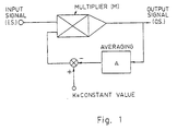
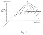
- Some signal processing performed in biological sensors such as the eye have been successfully modeled by a spatial, or non-causal feedback AGC algorithm, whose block diagram is schematically given in Fig. 1. In this model the input signal is multiplied by a difference of a constant and a non-causal average of the output signal. As a result, the transmission of this model to the average level of the input signal exhibits an asymptotic nature, according to curve A of Fig. 2.
- the generalized approximation of the said model constitutes the class of neighborhood transforms which actually cover many known signal processing techniques, such as convolution.
- Signal processing generally consists of three phases: preprocessing, data reduction, and recognition.
- preprocessing the complete signal is usually processed by algorithms which are unaware of the content of the signal, and merely improve its quality. Examples are histogram equalization, noise reduction, peak detection, smoothing, thresholding, etc.
- the preprocessing phase of signal processing requires the handling of a huge flow of information.
- Many preprocessing algorithms operate on small neighborhoods or segments of the signal at a time, while others, such as histogram processing and certain integral transforms, process the whole signal before any result can be generated.
- Some preprocessing systems are designed to imitate the human eye, but are merely approximations of what the eye can do.
- Some conventional image processing systems acquire images from an image acquisition unit, such as a camera, which produces each image in a raster scan format.
- the video signal is typically forwarded to a pipeline of neighborhood processors, such as convolvers, and integral processors such as histogram and fast Fourier transformers.
- the preprocessors typically generate their outputs in a raster scan format so that one preprocessor can directly feed into the next one.
- the approximate AGC algorithm in image processing is a special case of neighborhood transforms.
- a neighborhood transform is an image mapping operation where each pixel value of the output image is a function of the value of the corresponding pixel of the input image and the pixels in a local region surrounding it. Neighborhood transforms can use neighborhoods of arbitrary size, but most are of a specific size such as a cascaded series of transforms using 3x3 neighborhoods. These 3x3 neighborhoods involve only the eight nearest neighbors surrounding a given pixel to be processed.
- Homomorphic filters such as described in U.S. Patent No. 5,247,366, have been introduced to signal processing during the last decade. These are non-linear processors that essentially divide every sample of the original signal by the corresponding sample of Low-Pass filtered version of the original signal. Homomorphic filters can achieve bounded amounts of dynamic range reduction, however they are cumbersome to implement; potentially sensitive to errors, and highly demanding in computation time and hardware.
- causal feedback AGC has been known and used for many years in communication and signal conditioning.
- a causal averaging is commonly utilized by some type of Low-Pass Filter or an Integrator, that merely slows down and limits the signal rate of change in time.
- Low-Pass Filter or an Integrator that merely slows down and limits the signal rate of change in time.
- time-dependent AGC devices the response of which to video signals would necessarily depend on the direction in which the photographed scenery had been scanned by the camera a very unfavorable phenomenon.
- the processed sample value may depend on values of surrounding output samples, of which some may have not yet been processed.
- This type of repetitive algorithm may eventually converge to a value nearly identical with that one would obtain from a feedback AGC.
- the iterative process requires a great deal of processing time and memory, thus limiting its use in real time and increasing its cost.
- Image processing apparatus of the general type discussed above is described, e.g., in WO 90/01750, WO 90/01844 and WO 90/01845.
- the real time equalizer-enhancer apparatus comprises:
- the real time equalizer-enhancer apparatus comprises:
- the real time equalizer-enhancer apparatus comprises:
- the real time equalizer-enhancer apparatus comprises:
- a preferred device according to the present invention is a device wherein the components are dimensioned such that an input of equal steps evenly spaced, each fed thereto, results in filter response in the shape of flat values arranged along a monotonically increasing curve which averages them, which curve is asymptotic to a prescribed constant level regardless of the input signal level.
- Said output flat levels are separated by transitional zones in the form of doublets, each of which is composed of a negative peak that appears next to the lower side of the step and a positive peak appearing next to the higher side of the step.
- a signal processing apparatus comprising:
- a real time equalizer-enhancer apparatus 30 Illustrated in Fig. 3 is a real time equalizer-enhancer apparatus 30 which is illustrative of an application of the present invention. Other applications include commercial television, cable television, satellite television, video cameras, medical imaging devices, satellite imaging devices, high-fidelity audio amplifiers, video and audio recorders, video and audio communication links and storages, and the like.
- the real time equalizer-enhancer apparatus 30 is based on the feedback automatic gain control (AGC) concept that is mechanized by the use of non-causal, or double-sided averaging kernels as explained below.
- AGC feedback automatic gain control
- the equalizer-enhancer 30 includes a sampling switch 31 that feeds the samples of the input signal into a multi-tap analog delay line 32.
- the length of the delay line is arbitrary, however a sufficiently adequate minimum number of stages is 2.
- the delay of each stage of the delay line depends on the specific application to be utilized. For horizontal filtering only, of commercial Television Video, the stage delay should be in the order of 70 to 100 nano seconds, which approximately resembles the time duration of a single pixel. For this type of application, an example for appropriate delay line would be a product of either series 2211 or series 2214, manufactured by Data Delay Devices Inc. For vertical filtering only of the same type of signals, the stage delay must be exactly equal to the time duration of a single Television line which is in the order of 64 micro seconds.
- This type of synchronous delay can be performed by Charge Coupled Devices (CCD) type of analog delay lines, such as CXL 5001P or CXL 5001M, 1H CMOS-CCD, manufactured by Sony Corp., Japan.
- CCD Charge Coupled Devices
- the two types of delay lines should be alternately connected in series.
- Each tap of the delay line is connected to an input marked x of an analog multiplier 33.
- An example for an analog multiplier is AD-834, manufactured by Analog Devices Inc.
- each multiplier is connected to the output of an operational amplifier 34, with feedback resistors 35 and input summing resistors 36.
- the input resistors 36 are connected to the multipliers outputs and perform a non-causal weighted averaging of the outputs.
- the task of the operational amplifiers is to subtract the averaged output from a prescribed constant, and to feed the result back to the multipliers inputs.
- the various weights of the averaging in amplifiers 34 are determined by the quotients: (value of resistor 35)/(value of resistor 36).
- Each pair of multipliers define two weighted feedback paths.
- the weights can be determined in many ways. One useful way to prescribe a weight for a given path, is to have it proportional to some exponent of the number of taps that separate between the inputs of the two multipliers that define the corresponding feedback path. An important special case of the exponential weighting is the case where the exponent basis is unity (one). In this case all the weights are equal and the average is the common arithmetic average.
- the outputs of the analog multipliers 33 are further connected to a summing amplifier 37 that performs a linear combination of the multipliers outputs.
- the output of amplifier 37 constitutes the output signal of apparatus 30.
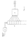
- Fig. 4 illustrates a simplified equalizer-enhancer apparatus 40, where the tapped delay line 32 of Fig. 3 has been replaced by a set of analog sample-hold elements 42.
- the switches 41 of the sample-hold cells make their contact each one at a time in a cyclic order, such that at each sampling instant the cell that holds the oldest data is being updated with the newest data.
- a possible example for the sample-hold elements is CLC940, manufactured by Comlinear Corp.
- the outputs of the sample-holds are connected to the inputs of a plurality of analog multipliers 43, in an arrangement similar to that of Fig. 3. Using a unity averaging exponent, a single operational amplifier 44, whose input resistors 45 are all identical in value can be used.
- the output signal of the equalizer-enhancer apparatus 40 is composed of the multipliers outputs, sampled at a cyclic order. This is performed by the plurality of analog switches 47, that feed the signals samples to an output memory buffer 48.
- the outputs of the delay lines 51 are converted into digital words by the plurality of Analog to Digital Converters 52.
- Said digital words, that represent a given neighborhood of the input signal are fed into a digital processor 53.
- Said digital processor is equipped with all the registers, data busses, adders/subtractors, multipliers/dividers, as well as timing generators and appropriate commands -- either in software or in hardware, so as it is capable of computing the output of a non causal feedback AGC model non itaratively, as an explicit function of the input signal only.
- This function requires only the four basic arithmetic operations and can be performed by most of the existing digital processors, such as the TMS-320/C30, manufactured by Texas Instruments Inc. Alternatively, the computations involved can be carried out by a Central Processing Unit (CPU) of any general-purpose host computer, such as the IBM/PC or alike. In the semi digital embodiment, the processor output is finally converted back into an analog signal by the Digital to Analog Converter (DAC) 54 of Fig. 5.
- DAC Digital to Analog Converter
- the input signal is sampled and converted into a sequence of digital words by the Analog to Digital Converter (ADC) 61, said words are fed into a plurality of digital shift registers, or memory buffers, 62.
- the outputs of the shift registers I memory buffers are fed into a digital processor 63, said processor computes the output of the non causal feedback AGC model non iteratively, as an explicit function of the input samples only.
- ADC Analog to Digital Converter
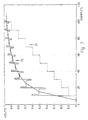
- the input signal is Graph 71 in Fig. 7. It consists of a series of 110 samples whose intensities are arranged in ten equal steps of 0.1 Volts each, covering together the range between 0 Volts and 1 Volt, and evenly spaced along the line of samples.
- the response of the filter to this input signal is given in Graph 72 of Fig. 7. It consists of a series of horizontal flat zones, separated by a series.of transitional zones. Each of the transitional zones is a doublet, composed of a negative peak followed by a positive peak.
- the flat zones are the filter responses to the corresponding horizontal segments of the input signal.
- the doublets of negative and positive peaks are the device responses to the corresponding transitions that separate between the stairs of the input signal.
- the equalization property of the present device can be appreciated from the values of the horizontal segments of the output signal. Those values are arranged on an asymptotic curve that can never exceed the value of 1, no matter how large the average level of the input signal is. This implies that the dynamic range compression ability of the present device per the average input is practically unlimited.
- the enhancement property can be measured if per each step of the output signal a quotient is calculated, which is the ratio between the difference of the positive and negative peaks of the doublet, and the difference between the two horizontal levels that are adjacent to the said doublet on both sides. In Fig. 8, the values of these quotients, as calculated from Graph 72 of Fig. 7, were plotted per all the steps between sample 20 and sample 100.
- the equalization-enhancement quotient which is the ratio between the device response to local changes and its response to the average, is in fact growing linearly with the average of the input signal.
- Graph 72 also shows a clear evidence to the non causal character of the present invention.
- the steps going either upward or downward in time in either case half of each of the transitional doublets would have precede the corresponding step in time.
- the response of any traditional causal feedback AGC would exhibit only an overshoot following a positive input step, and only an undershoot following a negative input step.
Landscapes
- Picture Signal Circuits (AREA)
- Filters That Use Time-Delay Elements (AREA)
- Control Of Amplification And Gain Control (AREA)
- Cable Transmission Systems, Equalization Of Radio And Reduction Of Echo (AREA)
- Complex Calculations (AREA)
Claims (16)
- Un dispositif égaliseur-accroisseur en temps réel comprenant :des moyens étant prévus pour combiner les sorties de ladite pluralité de multiplicateurs analogiques conformément à une règle de combinaison prédéterminée, des moyens étant également prévus pour soustraire ladite combinaison de sortie des multiplicateurs de valeurs de déviation constantes prescrites et pour retourner les résultats dans les entrées des multiplicateurs analogiques.une pluralité de multiplicateurs analogiques comportant chacun deux entrées, dont la première entrée reçoit un signal d'entrée échantillonné,au moins un amplificateur opérationnel équipé d'une résistance de feed-back, dont la sortie est connectée à la seconde entrée de l'un ou plusieurs de la pluralité des multiplicateurs analogiques ; etune pluralité de résistances de sommation connectées entre la sortie de chacun desdits multiplicateurs analogiques et l'entrée de l'amplificateur opérationnel,
- Un dispositif égaliseur-accroisseur en temps réel selon la revendication 1 comprenant :dans lequel chacune de ces lignes à retard analogiques est connectée à une extrémité au dit commutateur d'échantillonnage et à l'autre extrémité à la première entrée de l'un des multiplicateurs analogiques ;un commutateur d'échantillonnage destiné à alimenter les échantillons du signal d'entrée dans une pluralité de lignes à retard analogiques, avec ou sans prises,
et comprenant au surplus :des amplificateurs additionnels prévus avec une résistance de feed-back, chaque sortie d'amplificateur opérationnel étant connectée à l'entrée d'au moins un multiplicateur analogique, l'entrée de chaque amplificateur opérationnel étant connectée à plusieurs multiplicateurs analogiques par l'intermédiaire d'une ou plusieurs résistances de sommation ;des résistances de sommation additionnelles connectées entre la sortie de chacun desdits multiplicateurs analogiques et l'entrée des amplificateurs opérationnels analogiques ; etun amplificateur de sommation destiné à combiner les sorties de ladite pluralité de multiplicateurs analogiques de manière à fournir le signal de sortie du dispositif d'égaliseur-accroisseur en temps réel. - In dispositif égaliseur-accroisseur en temps réel selon la revendication 1 comprenant:une pluralité d'éléments de retenue d'échantillons destinés à alimenter les échantillons du signal d'entrée dans un ordre cyclique à la première entrée de chacun desdits multiplicateurs analogiques ;exactement un amplificateur opérationnel étant prévu avec la résistance de feed-back, ledit amplificateur opérationnel étant connecté à chacun desdits multiplicateurs analogiques, la sortie de l'amplificateur opérationnel étant connectée à l'entrée de tous les multiplicateur analogiques ;ladite pluralité de résistances de sommation étant connectées entre la sortie de chacun desdits multiplicateurs analogiques et l'entrée de l'amplificateur opérationnel ;une pluralité de commutateurs analogiques étant connectés à la sortie de l'un desdits multiplicateurs analogiques de manière à alimenter les échantillons de signaux à des mémoires tampons.
- Dispositif selon l'une quelconque des revendications 1 à 3, dans lequel les composants sont dimenslonnés de manière telle qu'une entrée d'étapes égales espacées de manière régulière, chacune étant alimentée au dit dispositif, a pour conséquence une réponse de filtrage sous forme de valeurs plates disposées le long d'une courbe croissante de façon monotone qui en représente les moyennes, laquelle courbe étant asymptote à un niveau constant prescrit quel que soit le niveau du signal d'entrée, lesdits niveaux plats de sortie étant séparés par des zones de transition sous forme de doublets dont chacun est composé d'un pic négatif qui apparaít après le côté plus bas de l'étape et un pic positif qui apparaít après le côté plus haut de l'étape.
- Un dispositif de traitement de signaux comprenant :un dispositif égaliseur-accroisseur en temps réel selon la revendication 1,un dispositif d'échantillonnage et de stockage analogique destiné à procéder à l'échantillonnage et au stockage d'une représentation échantillonnée de données d'un signal d'entrée, connecté à l'entrée dudit dispositif égaliseur-accroisseur en temps réel,un dispositif d'échantillonnage et de stockage analogique destiné à l'échantillonnage et au stockage d'une représentation échantillonnée de données d'un signal de sortie, connecté à la sortie dudit dispositif égaliseur-accroisseur en temps réel.
- Montage selon la revendication 5, dans lequel lesdits dispositifs d'échantillonnage et de stockage fonctionnent en ordre cyclique.
- Montage selon la revendication 5, dans lequel lesdits dispositifs d'échantillonnage et de stockage comprennent des commutateurs analogiques.
- Montage selon la revendication 5, dans lequel lesdits dispositifs d'échantillonnage et de stockage comprennent des mémoires analogiques.
- Montage selon la revendication 8, dans lequel lesdites mémoires analogiques comprennent des lignes à retard analogiques additionnelles.
- Montage selon la revendication 8, dans lequel lesdites mémoires analogiques comprennent des lignes à retard du type Dispositifs Chargés Couplés (CCD).
- Montage selon la revendication 8, dans lequel lesdites mémoires analogiques sont remplacées par des compteurs de déplacement digitaux ou des mémoires tampons.
- Montage selon la revendication 5, dans lequel lesdits dispositifs d'échantillonnage et de stockage comprennent des Convertisseurs Analogique / Digitaux (ADCs).
- Montage selon l'une quelconque des revendications 1 à 5, dans lequel les sorties des multiplicateurs sont calculées digitalement conformément à des algorithmes non récursifs de forme analogique fermée.
- Montage selon la revendication 13, dans lequel ledit calcul digital des sorties des multiplicateurs est réalisé par un calculateur hôte conformément aux algorithmes non récursifs de forme fermée.
- Montage selon la reveidication 13, dans lequel lesdites sorties de multiplicateur calculées digitalement sont reconverties en un signal analogique par un Convertisseur Digital / Analogique (DAC).
- Montage selon la revendication 5, dans lequel ledit dispositif égaliseur-accroisseur en temps réel comprend des multiplicateurs analogiques additionnels.
Applications Claiming Priority (3)
| Application Number | Priority Date | Filing Date | Title |
|---|---|---|---|
| IL10982494A IL109824A (en) | 1994-05-30 | 1994-05-30 | Signal processing device |
| IL10982494 | 1994-05-30 | ||
| PCT/US1995/006780 WO1995033306A1 (fr) | 1994-05-30 | 1995-05-26 | Dispositif de traitement de signaux |
Publications (2)
| Publication Number | Publication Date |
|---|---|
| EP0763280A1 EP0763280A1 (fr) | 1997-03-19 |
| EP0763280B1 true EP0763280B1 (fr) | 2002-04-03 |
Family
ID=11066181
Family Applications (1)
| Application Number | Title | Priority Date | Filing Date |
|---|---|---|---|
| EP95923673A Expired - Lifetime EP0763280B1 (fr) | 1994-05-30 | 1995-05-26 | Dispositif de traitement de signaux |
Country Status (6)
| Country | Link |
|---|---|
| EP (1) | EP0763280B1 (fr) |
| JP (1) | JP3398842B2 (fr) |
| AU (1) | AU2815095A (fr) |
| DE (1) | DE69526224T2 (fr) |
| IL (1) | IL109824A (fr) |
| WO (1) | WO1995033306A1 (fr) |
Families Citing this family (5)
| Publication number | Priority date | Publication date | Assignee | Title |
|---|---|---|---|---|
| US7489814B2 (en) | 2003-02-21 | 2009-02-10 | Ramot At Tel Aviv University Ltd. | Method of and device for modulating a dynamic range of still and video images |
| US8897524B2 (en) | 2007-10-29 | 2014-11-25 | Ramot At Tel-Aviv University Ltd. | Method and device for processing computerized tomography images |
| EP2235677A1 (fr) | 2007-12-20 | 2010-10-06 | Ramot at Tel-Aviv University Ltd. | Procédé et appareil de traitement d'images |
| WO2012017440A1 (fr) | 2010-08-05 | 2012-02-09 | Ramot At Tel-Aviv University Ltd. | Procédé et système de traitement d'une image représentant plusieurs échelles |
| DE102018115991B4 (de) * | 2018-07-02 | 2023-12-07 | Basler Ag | Digitale schaltung zur korrektur eines vignettierungseffekts in werten von pixeln eines bildes einer elektronischen kamera |
Family Cites Families (5)
| Publication number | Priority date | Publication date | Assignee | Title |
|---|---|---|---|---|
| US4063200A (en) * | 1976-02-10 | 1977-12-13 | Westinghouse Electric Corporation | Hybrid multiplexed filter |
| US4417317A (en) * | 1980-02-04 | 1983-11-22 | Westinghouse Electric Corp. | Adaptive analog processor |
| US4757373A (en) * | 1985-11-14 | 1988-07-12 | U.S. Philips Corporation | Amplifier circuit operative with an adaptive signal compression |
| JPS63266983A (ja) * | 1987-12-23 | 1988-11-04 | Canon Inc | 映像信号処理装置 |
| US5245296A (en) | 1992-07-10 | 1993-09-14 | Miller Francis A | Audio amplifier circuit and method of operation |
-
1994
- 1994-05-30 IL IL10982494A patent/IL109824A/xx not_active IP Right Cessation
-
1995
- 1995-05-26 AU AU28150/95A patent/AU2815095A/en not_active Abandoned
- 1995-05-26 JP JP50111296A patent/JP3398842B2/ja not_active Expired - Fee Related
- 1995-05-26 WO PCT/US1995/006780 patent/WO1995033306A1/fr not_active Ceased
- 1995-05-26 DE DE69526224T patent/DE69526224T2/de not_active Expired - Fee Related
- 1995-05-26 EP EP95923673A patent/EP0763280B1/fr not_active Expired - Lifetime
Also Published As
| Publication number | Publication date |
|---|---|
| EP0763280A1 (fr) | 1997-03-19 |
| WO1995033306A1 (fr) | 1995-12-07 |
| IL109824A (en) | 1999-12-31 |
| DE69526224T2 (de) | 2002-10-02 |
| AU2815095A (en) | 1995-12-21 |
| JP3398842B2 (ja) | 2003-04-21 |
| IL109824A0 (en) | 1994-08-26 |
| JPH10506241A (ja) | 1998-06-16 |
| DE69526224D1 (de) | 2002-05-08 |
Similar Documents
| Publication | Publication Date | Title |
|---|---|---|
| Narendra et al. | Real-time adaptive contrast enhancement | |
| EP0045596A2 (fr) | Filtre pour traitement d'image | |
| Kim et al. | Recursive high-resolution reconstruction of blurred multiframe images | |
| US4213150A (en) | Real-time edge processing unit | |
| US4442454A (en) | Image processing method using a block overlap transformation procedure | |
| US5729631A (en) | Image noise reduction system using a wiener variant filter in a pyramid image representation | |
| JP3251127B2 (ja) | 映像データ処理方式 | |
| JPH034680A (ja) | 画像データの増強方法およびカラー画像データの増強方法 | |
| US4328425A (en) | Filter for image pixels | |
| US20070009171A1 (en) | Image processor, image processing method, program and recording medium | |
| EP0763280B1 (fr) | Dispositif de traitement de signaux | |
| EP0350121A1 (fr) | Circuit intégré et dispositif de traitement d'images | |
| EP0450260B1 (fr) | Circuit de filtrage pour signaux numériques | |
| US5850357A (en) | Signal processing device | |
| US6643412B1 (en) | Method and apparatus for high speed convolution | |
| Hall | A comparison of computations for spatial frequency filtering | |
| KR100550676B1 (ko) | 2-차원 피라미드 필터 구조 | |
| CN111383188A (zh) | 一种图像处理方法、系统及终端设备 | |
| JP4323808B2 (ja) | 二次元ピラミッド・フィルタ・アーキテクチャ | |
| US6662200B2 (en) | Multiplierless pyramid filter | |
| EP0466252A2 (fr) | Procédé et dispositif pour la restitution d'images et signaux dégradés après convolution | |
| US20020184276A1 (en) | Two-dimensional pyramid filter architecture | |
| Aizenberg et al. | Extraction and localization of important features an gray-scale images: Implementation on the CNN | |
| US20200160824A1 (en) | Noise Reduction Filter for Signal Processing | |
| US20020174154A1 (en) | Two-dimensional pyramid filter architecture |
Legal Events
| Date | Code | Title | Description |
|---|---|---|---|
| PUAI | Public reference made under article 153(3) epc to a published international application that has entered the european phase |
Free format text: ORIGINAL CODE: 0009012 |
|
| 17P | Request for examination filed |
Effective date: 19961227 |
|
| AK | Designated contracting states |
Kind code of ref document: A1 Designated state(s): DE FR GB IT NL |
|
| 17Q | First examination report despatched |
Effective date: 20000412 |
|
| RAP1 | Party data changed (applicant data changed or rights of an application transferred) |
Owner name: TRUSIGHT LTD. |
|
| GRAG | Despatch of communication of intention to grant |
Free format text: ORIGINAL CODE: EPIDOS AGRA |
|
| GRAG | Despatch of communication of intention to grant |
Free format text: ORIGINAL CODE: EPIDOS AGRA |
|
| GRAG | Despatch of communication of intention to grant |
Free format text: ORIGINAL CODE: EPIDOS AGRA |
|
| GRAH | Despatch of communication of intention to grant a patent |
Free format text: ORIGINAL CODE: EPIDOS IGRA |
|
| RAP1 | Party data changed (applicant data changed or rights of an application transferred) |
Owner name: TRUSIGHT LTD. |
|
| REG | Reference to a national code |
Ref country code: GB Ref legal event code: IF02 |
|
| GRAH | Despatch of communication of intention to grant a patent |
Free format text: ORIGINAL CODE: EPIDOS IGRA |
|
| GRAA | (expected) grant |
Free format text: ORIGINAL CODE: 0009210 |
|
| AK | Designated contracting states |
Kind code of ref document: B1 Designated state(s): DE FR GB IT NL |
|
| REF | Corresponds to: |
Ref document number: 69526224 Country of ref document: DE Date of ref document: 20020508 |
|
| ET | Fr: translation filed | ||
| PLBE | No opposition filed within time limit |
Free format text: ORIGINAL CODE: 0009261 |
|
| STAA | Information on the status of an ep patent application or granted ep patent |
Free format text: STATUS: NO OPPOSITION FILED WITHIN TIME LIMIT |
|
| 26N | No opposition filed |
Effective date: 20030106 |
|
| PGFP | Annual fee paid to national office [announced via postgrant information from national office to epo] |
Ref country code: GB Payment date: 20030519 Year of fee payment: 9 |
|
| PGFP | Annual fee paid to national office [announced via postgrant information from national office to epo] |
Ref country code: FR Payment date: 20030527 Year of fee payment: 9 |
|
| PGFP | Annual fee paid to national office [announced via postgrant information from national office to epo] |
Ref country code: NL Payment date: 20030528 Year of fee payment: 9 |
|
| PGFP | Annual fee paid to national office [announced via postgrant information from national office to epo] |
Ref country code: DE Payment date: 20030715 Year of fee payment: 9 |
|
| PG25 | Lapsed in a contracting state [announced via postgrant information from national office to epo] |
Ref country code: GB Free format text: LAPSE BECAUSE OF NON-PAYMENT OF DUE FEES Effective date: 20040526 |
|
| PG25 | Lapsed in a contracting state [announced via postgrant information from national office to epo] |
Ref country code: NL Free format text: LAPSE BECAUSE OF NON-PAYMENT OF DUE FEES Effective date: 20041201 Ref country code: DE Free format text: LAPSE BECAUSE OF NON-PAYMENT OF DUE FEES Effective date: 20041201 |
|
| GBPC | Gb: european patent ceased through non-payment of renewal fee | ||
| PG25 | Lapsed in a contracting state [announced via postgrant information from national office to epo] |
Ref country code: FR Free format text: LAPSE BECAUSE OF NON-PAYMENT OF DUE FEES Effective date: 20050131 |
|
| NLV4 | Nl: lapsed or anulled due to non-payment of the annual fee |
Effective date: 20041201 |
|
| REG | Reference to a national code |
Ref country code: FR Ref legal event code: ST |
|
| PG25 | Lapsed in a contracting state [announced via postgrant information from national office to epo] |
Ref country code: IT Free format text: LAPSE BECAUSE OF NON-PAYMENT OF DUE FEES Effective date: 20050526 |