EP0763377B1 - Abgasreinigungssystem - Google Patents
Abgasreinigungssystem Download PDFInfo
- Publication number
- EP0763377B1 EP0763377B1 EP96108931A EP96108931A EP0763377B1 EP 0763377 B1 EP0763377 B1 EP 0763377B1 EP 96108931 A EP96108931 A EP 96108931A EP 96108931 A EP96108931 A EP 96108931A EP 0763377 B1 EP0763377 B1 EP 0763377B1
- Authority
- EP
- European Patent Office
- Prior art keywords
- solid
- liquid separation
- filtrate
- slurry
- flue gas
- Prior art date
- Legal status (The legal status is an assumption and is not a legal conclusion. Google has not performed a legal analysis and makes no representation as to the accuracy of the status listed.)
- Expired - Lifetime
Links
Images



Classifications
-
- B—PERFORMING OPERATIONS; TRANSPORTING
- B01—PHYSICAL OR CHEMICAL PROCESSES OR APPARATUS IN GENERAL
- B01D—SEPARATION
- B01D53/00—Separation of gases or vapours; Recovering vapours of volatile solvents from gases; Chemical or biological purification of waste gases, e.g. engine exhaust gases, smoke, fumes, flue gases, aerosols
- B01D53/34—Chemical or biological purification of waste gases
- B01D53/74—General processes for purification of waste gases; Apparatus or devices specially adapted therefor
-
- B—PERFORMING OPERATIONS; TRANSPORTING
- B01—PHYSICAL OR CHEMICAL PROCESSES OR APPARATUS IN GENERAL
- B01D—SEPARATION
- B01D53/00—Separation of gases or vapours; Recovering vapours of volatile solvents from gases; Chemical or biological purification of waste gases, e.g. engine exhaust gases, smoke, fumes, flue gases, aerosols
- B01D53/34—Chemical or biological purification of waste gases
-
- B—PERFORMING OPERATIONS; TRANSPORTING
- B01—PHYSICAL OR CHEMICAL PROCESSES OR APPARATUS IN GENERAL
- B01D—SEPARATION
- B01D53/00—Separation of gases or vapours; Recovering vapours of volatile solvents from gases; Chemical or biological purification of waste gases, e.g. engine exhaust gases, smoke, fumes, flue gases, aerosols
- B01D53/34—Chemical or biological purification of waste gases
- B01D53/46—Removing components of defined structure
- B01D53/48—Sulfur compounds
- B01D53/50—Sulfur oxides
- B01D53/501—Sulfur oxides by treating the gases with a solution or a suspension of an alkali or earth-alkali or ammonium compound
-
- B—PERFORMING OPERATIONS; TRANSPORTING
- B01—PHYSICAL OR CHEMICAL PROCESSES OR APPARATUS IN GENERAL
- B01D—SEPARATION
- B01D53/00—Separation of gases or vapours; Recovering vapours of volatile solvents from gases; Chemical or biological purification of waste gases, e.g. engine exhaust gases, smoke, fumes, flue gases, aerosols
- B01D53/34—Chemical or biological purification of waste gases
- B01D53/46—Removing components of defined structure
- B01D53/48—Sulfur compounds
- B01D53/50—Sulfur oxides
- B01D53/501—Sulfur oxides by treating the gases with a solution or a suspension of an alkali or earth-alkali or ammonium compound
- B01D53/504—Sulfur oxides by treating the gases with a solution or a suspension of an alkali or earth-alkali or ammonium compound characterised by a specific device
-
- C—CHEMISTRY; METALLURGY
- C02—TREATMENT OF WATER, WASTE WATER, SEWAGE, OR SLUDGE
- C02F—TREATMENT OF WATER, WASTE WATER, SEWAGE, OR SLUDGE
- C02F2103/00—Nature of the water, waste water, sewage or sludge to be treated
- C02F2103/18—Nature of the water, waste water, sewage or sludge to be treated from the purification of gaseous effluents
Definitions
- This invention relates to a flue gas treating apparatus wherein the dumping disposal of sludge produced in a waste water treating apparatus is not required and, moreover, the concentration of impurities in the absorbent slurry within a desulfurization apparatus can be kept on a low level so as to facilitate, for example, the maintenance of a high degree of desulfurization and the maintenance of complete oxidation for the efficient recovery of high-quality gypsum.
- DE 3 145 779 discloses a method for washing hot exhaust air containing hydrofluoric acid or hydrofluoric acid and sulfur dioxide as well as for clarifying clay and/or glaze containing waste water, both from a ceramic industry plant.
- the method provides that hot exhaust air is washed in a wash tower with washing water.
- the hydrofluoric acid then contained in the washing water is - after treatment - removed by sedimentation (liquid-solid separation).
- the clay and/or glaze contained in the waste water is neutralized and washed and - after treatment - also removed in a sedimentation step (liquid-solid separation).
- the hydrofluoric acid is kept at pH less than 3.5 through addition of washing water and removal of hydrofluoric acid contained in the washing water.
- the hydrofluoric acid-containing washing water and the clay and/or glaze-containing waste water are both collected in a tank and the impurities of the clay and/or glaze-containing waste water are cleaved by the hydrofluoric acid-containing washing water and both the washing and the waste water are together neutralized by lime milk.
- the calcium fluoride and calcium sulfate formed by the neutralization and the clay and/or glaze material undergo liquid-solid separation in the same sedimentation tank. At least a portion of the clarified water from the sedimentation tank is diluted by the hydrofluoric acid-containing washing water.
- the residue solid particles of the sedimentation tank are further processed in a filter press.
- the obtained filtrate is introduced through a sedimentation tank into a buffer tank, where some of the filtrate is overflown for discharge to the main outfall of a waste water clarification plant and the other is returned to the wash tower.
- the method is devised and controlled in such a way that hydrofluoric acid is removed without any simultaneous separation of sulfur dioxide. This method is not devised to desulfurize flue gas with a substantial content of sulfur dioxide.
- flue gas desulfurization apparatus wherein flue gas is brought into contact with an absorbent slurry (containing a calcium compound such as limestone) in an absorption tower so as to have sulfur dioxide present in the flue gas absorbed into the slurry, and the slurry having undergone contact with flue gas is oxidized and then subjected to solid-liquid separation so as to obtain gypsum as a by-product have come to be widely used in electric power plants and the like.
- the filtrate (consisting essentially of water) resulting from the separation of gypsum is recycled for use as the liquid component constituting the absorbent slurry.
- waste water treatment including the removal of harmful materials, COD control, decomposition, absorption, pH adjustment and the like is carried out in order to clear the standards for waste water.
- a considerable amount of sludge is produced during this treatment and poses a problem because great expense is required for its disposal.
- the solid component of this sludge consists of Mg(OH) 2 and CaSO 4 ⁇ 2H 2 O (gypsum) that are formed by the reaction of MgSO 4 contained in the filtrate with the neutralizing agent [Ca(OH) 2 ], as well as Fe(OH) 3 and Al(OH) 3 that are formed from Fe and Al contained in the filtrate and precipitated by pH adjustment from the acid to the alkaline side.
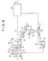
- This system includes a desulfurization apparatus comprising an absorption tower 1 and the like, and is equipped with a waste water treating apparatus 20 for treating and discharging part of the circulating water of the desulfurization apparatus.
- the desulfurization apparatus is provided with a rotating-arm air sparger 3 for blowing air C into the slurry within the tank 2 of absorption tower 1 in the form of fine air bubbles while stirring the slurry, so that the absorbent slurry having sulfur dioxide absorbed therein is brought into efficient contact with air C and thereby completely oxidized to form gypsum.
- untreated flue gas A is introduced into a flue gas inlet section 1a of absorption tower 1 and brought into contact with an absorption slurry injected from header pipes 5 by means of a circulating pump 4 so as to absorb and remove sulfur dioxide present in untreated flue gas A.
- the resulting flue gas is discharged as treated flue gas B from a flue gas outlet section 1b.
- the absorbent slurry injected from header pipes 5 flows downward through a layer of packing material 6 while absorbing sulfur dioxide, and enters tank 2 where it is oxidized by contact with a large number of air bubbles blown thereinto while being stirred with air sparger 3, and then undergoes a neutralization reaction to form gypsum.
- the predominant reactions occurring in the course of these treatments are represented by the following reaction formulas (1) to (3).
- the slurry within tank 2 comes to have suspended or dissolved therein gypsum and a small amount of limestone used as absorbent.
- This slurry is withdrawn by means of a slurry pump 7 and fed to a mixing tank 8 where it is mixed with a relatively slight amount of sludge D withdrawn from the waste water treating apparatus.
- the slurry having a slight amount of sludge D mixed therein is transferred to a vacuum belt filter 10 by means of a slurry pump 9 and subjected to solid-liquid separation.
- gypsum E having a low water content (usually of about 10%) and containing a light amount of impurities.
- filtrate F from vacuum belt filter 10 is sucked into a vacuum chamber 12 which is evacuated by a vacuum pump 11, and transferred to a filtrate tank 13 by way of this vacuum chamber 12.
- Most of filtrate F within filtrate tank 13 is sucked out by means of a pump 14 and transferred to a slurry tank 15 where an alkaline material G (such as limestone) is added thereto.
- the resulting absorbent slurry is recycled to tank 2 by means of a slurry pump 16.
- the supply of water to this desulfurization apparatus is not shown, this can be done, for example, by supplying clean water containing no impurities to slurry tank 15 as required.
- part of filtrate F within filtrate tank 13 is sucked out by means of a pump 17 and transferred to waste water treating apparatus 20 where it is subjected to waste water treatment and then disposed of, for example, by discharging it as waste fluid H.
- Sludge D produced in waste water treating apparatus 20 is withdrawn to the side of the desulfurization apparatus and, as described above, mixed with the slurry withdrawn from absorption tower 1 in mixing tank 8.
- the solid component thereof is incorporated into gypsum E formed as a by-product.
- the purity of gypsum E is not reduced to such an extent as to preclude its use as a material for the manufacture of gypsum plasterboards and cement.
- sludge D produced in waste water treating apparatus 20 is disposed of by incorporating it into gypsum E obtained as a by-product in the desulfurization apparatus.
- This is highly advantageous in that troublesome operations for subjecting sludge D to special solidification treatment prior to dumping, as well as equipment used therefor, are unnecessary.
- the slurry (before solid-liquid separation) withdrawn from the absorption tower and sludge D (before solid-liquid separation) withdrawn from waste water treating apparatus 20 are previously mixed in mixing tank 8 and then collectively dehydrated by belt filter 10.
- part of the circulating water which is withdrawn from the desulfurization apparatus and transferred to the waste water treating system in order to remove impurities therefrom is returned to the slurry within the desulfurization apparatus.
- impurities such as chlorine
- a preferred embodiment of the present invention is defined in claim 2.
- the solid component of sludge produced in the waste water treating apparatus is disposed of by incorporating it into gypsum, while the liquid component of the sludge (i.e., the second filtrate) is wholly introduced into the waste water treating apparatus together with part of the first filtrate and, therefore, does not return to the absorbent slurry within the desulfurization apparatus.
- two solid-liquid separation regions for carrying out solid-liquid separation independently are defined on both lateral sides of the belt filter, and the sludge is subjected to solid-liquid separation in one of the solid-liquid separation regions while the slurry having undergone contact with flue gas in the desulfurization apparatus is subjected to solid-liquid separation in the other solid-liquid separation region.
- solid-liquid separation of the sludge and the slurry having undergone contact with flue gas can be carried out under different conditions (pressure conditions) by use of a single belt filter.
- this apparatus is constructed so that the solid component of sludge produced in the waste water treating apparatus is disposed of by incorporating it into gypsum, the liquid component of the sludge (i.e., the second filtrate) is positively prevented from returning to the absorbent slurry within the desulfurization apparatus.
- the above-described preferred embodiment has the unique advantage that solid-liquid separation of the sludge and the slurry can be carried out under different conditions (pressure conditions) by use of a single belt filter, resulting in a further reduction in equipment cost and operating cost.
- FIG. 1 to 3 A first example of the present invention is described hereinbelow with reference to FIGs. 1 to 3.
- the same elements as mentioned above in connection with the conventional system illustrated in FIG. 6 are designated by the same reference numerals, and the explanation of common parts is omitted.
- the flue gas treating system in accordance with this example is equipped with a belt filter 30 used for solid-liquid separation of the slurry withdrawn from absorption tower 1, and a belt filter (or solid-liquid separation means) 40 used for independent solid-liquid separation of sludge D withdrawn from waste water treating apparatus 20.
- these belt filters 30 and 40 are disposed so that their ends at which the resulting solid material is discharged are opposed to each other.
- the solid materials (i.e., gypsum and a slight amount of impurities) separated by these belt filters 30 and 40 are mixed to some extent by being carried on an identical belt conveyor 50 as shown in FIG. 1, and collectively recovered as gypsum E.
- a mixer may be installed in order to mix the solid materials separated by belt filters 30 and 40.
- the belt conveyor 50 shown in FIG. 1 travels in a direction perpendicular to the traveling directions of belt filters 30 and 40 (i.e., a direction perpendicular to the plane of the figure), it may be disposed in parallel or oblique relationship to belt filters 30 and 40.
- the filtrates separated by belt filters 30 and 40 are sucked out through two separate lines and recovered. More specifically, the slurry filtrate F1 separated by belt filter 30 (i.e., the first filtrate) is sucked into a vacuum chamber 32 evacuated by a vacuum pump 31, and then transferred to a first filtrate tank 33 by way of this vacuum chamber 32.
- the slurry filtrate F2 separated by belt filter 40 i.e., the second filtrate is sucked into a vacuum chamber 42 evacuated by a vacuum pump 41, and then transferred to a second filtrate tank 43 by way of this vacuum chamber 42.
- First filtrate tank 33 and second filtrate tank 43 are connected by an overflow path 33a, so that part of first filtrate F1 within first filtrate tank 33 is introduced into second filtrate tank 43 by way of this overflow path 33a and, together with second filtrate F2, transferred to waste water treating apparatus 20.
- the liquid levels are controlled, for example, by presetting or regulating the delivery rates of pumps 14 and 17, so that second filtrate F2 within second filtrate tank 43 will not flow backward to first filtrate tank 33.
- a cyclone or other separator for preliminarily subjecting the slurry or sludge to some degree of solid-liquid separation may be installed on the upstream side of each belt filter 30 or 40.
- the separated liquid component may be, for example, returned directly to tank 2 or introduced into the corresponding vacuum chamber 32 or 42.
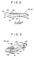
- Each of belt filters 30 and 40 is a vacuum filter of the horizontal belt type and may be constructed, for example, as illustrated in FIG. 2 and FIG. 3 (perspective view).
- each belt filter 30 or 40 comprises two rotatably supported drums 61 and 62; a perforated belt 63 mounted on and driven by these drums 61 and 62 so as to travel horizontally; a plurality of guide rollers 64 disposed around perforated belt 63 so as to lie in parallel with drums 61 and 62; an endless belt of filter cloth 65 guided and driven by these guide rollers 64 so that, on the upper side, it travels with its back surface in contact with perforated belt 63; a slurry loading pan 66 and a vacuum pan (or vacuum space) 67 disposed so that their upper open ends face the back surface of the upper side of perforated belt 63; and a loader 68 for supplying a slurry or the like to filter cloth 65 at the upstream end (or loading site) of perforated belt 63.
- Slurry loading pan 66 is disposed so as to cover a definite upstream range (i.e., the filtration range) of perforated belt 63 where a slurry or the like is loaded onto filter cloth 65 and subjected to simple gravity filtration therethrough, and serves to receive the filtrate separated from the slurry or the like loaded onto filter cloth 65.
- This slurry loading pan 66 is designed so that the filtrate can be discharged as required.
- Vacuum pan 67 which constitutes the vacuum space of the present invention, is disposed so as to cover a definite downstream range (i.e., the dehydration range) of perforated belt 63.
- vacuum pan 67 is designed so that its upper open end is in sliding contact with the back surface of perforated belt 63 while maintaining sealability, and is connected with the corresponding vacuum chamber as shown in FIG. 2.
- loader 68 comprises a divergent nozzle having an upper end, which is connected with a pipeline (not shown) for supplying a slurry or the like, and a lower open end, which is widen toward a tip, and serves to distribute the slurry or the like evenly along the width of filter cloth 65.
- An absorbent slurry is fed from slurry tank 15 to tank 2 by means of slurry pump 16.
- slurry pump 16 On the basis of the above-described functions of circulating pump 4 and rotating-arm air sparger 3, the desulfurization of flue gas and the formation of gypsum as a by-product are effected in the same manner as described above in connection with the conventional flue gas treating system.
- the slurry within tank 2 has gypsum and a small amount of limestone suspended or dissolved therein.
- part of the slurry within tank 2 is withdrawn by means of slurry pump 7 and transferred directly to belt filter 30 where it is subjected to solid-liquid separation.
- sludge D produced in waste water treating apparatus 20 is transferred to belt filter 40 where it is subjected to solid-liquid separation independently of the aforesaid slurry.
- the solid materials (comprising gypsum and a slight amount of impurities) separated by these belt filters 30 and 40 are mixed to some extent by being carried on an identical belt conveyor 50 as shown in FIG. 1, and collectively recovered as gypsum E. Consequently, the troublesome dumping disposal of sludge D including its solidification is not required.
- filtrates F1 and F2 separated by belt filters 30 and 40 are independently sucked out through the above-described two lines and transferred to first filtrate tank 33 and second filtrate tank 43, respectively.
- Part of first filtrate F1 within first filtrate tank 33 is introduced into second filtrate tank 43 by way of overflow path 33a and, together with second filtrate F2, transferred to waste water treating apparatus 20.
- second filtrate F2 within second filtrate tank 43 is prevented from flowing backward to first filtrate tank 33.
- FIGs. 4 and 5 a second example of the present invention is described hereinbelow with reference to FIGs. 4 and 5.
- the same elements as mentioned above in connection with the system of the first example illustrated in FIGs. 1 to 3 are designated by the same reference numerals, and the explanation of common parts is omitted.
- the flue gas treating system in accordance with this example is equipped with a single belt filter 70.
- this belt filter 70 has a partition 71 for dividing slurry loading pan 66 and vacuum pan 67 along the width of belt-like filter cloth 65.
- two solid-liquid separation regions 72 and 73 for carrying out solid-liquid separation independently are defined on both lateral sides of belt filter 70, and two loaders 68a and 68b are installed at the upstream end of these solid-liquid separation regions 72 and 73, respectively.
- one solid-liquid separation region 72 of vacuum pan 67 is connected to vacuum chamber 42, and sludge D from waste water treating apparatus 20 is supplied to loader 68a associated with this solid-liquid separation region 72.
- the other solid-liquid separation region 73 of vacuum pan 67 is connected to vacuum chamber 32, and the slurry having undergone contact with flue gas and withdrawn from absorption tower 2 is supplied to loader 68b associated with this solid-liquid separation region 73.
- sludge D is subjected to solid-liquid separation in solid-liquid separation region 72, while the slurry from absorption tower 2 is subjected to solid-liquid separation in solid-liquid separation region 73.
- the pressure (or degree of vacuum) for vacuum separation can be adjusted to the optimum value according to the properties (such as particle diameter) of sludge D or the slurry, by controlling the pressure of the corresponding vacuum chamber 32 or 42.
- the slurry having undergone contact with flue gas and withdrawn from absorption tower 2 and sludge D withdrawn from waste water treating apparatus 20 are subjected to solid-liquid separation independently, and the liquid component of sludge D is surely reintroduced into waste water treating apparatus 20 and treated therein without returning to the slurry within the desulfurization apparatus. Consequently, similarly to the first example, it is readily possible to achieve a high degree of desulfurization and good corrosion resistance of the equipment and recover high-quality gypsum efficiently, while securing the ease of disposal of sludge D.
- this example has the unique advantage that only one belt filter is required, resulting in a further reduction in equipment cost and operating cost.
- the present invention is not limited to the above-described examples, but may be practiced in various ways.
- the first solid-liquid separation means of the present invention is not limited to a belt filter but may comprise a centrifugal separator or the like.
Landscapes
- Engineering & Computer Science (AREA)
- Chemical & Material Sciences (AREA)
- Environmental & Geological Engineering (AREA)
- Health & Medical Sciences (AREA)
- Biomedical Technology (AREA)
- Analytical Chemistry (AREA)
- General Chemical & Material Sciences (AREA)
- Oil, Petroleum & Natural Gas (AREA)
- Chemical Kinetics & Catalysis (AREA)
- Treating Waste Gases (AREA)
Claims (2)
- Rauchgasbehandlungsvorrichtung miteinem Entschwefelungsapparat (1, 2) mit einem Absorptionsturm (1), in dem Rauchgas mit einer eine Kalziumverbindung enthaltenden Aufschlämmung in Kontakt gebracht wird, um im Abgas vorhandenes Schwefeldioxid in der Aufschlämmung zu absorbieren,einem Einlass für Luft (C) zum Oxidieren der mit dem Rauchgas in Kontakt gebrachten Aufschlämmung;einem ersten Fest-Flüssig-Trennapparat (30), mit dem die oxidierte Aufschlämmung einer ersten Fest-Flüssig-Trennung zur Gewinnung von Gips (E) als Nebenprodukt und einem ersten Filtrat (F1) unterworfen wird;einem Abwasserbehandlungsapparat (20) zur Behandlung eines Teils des ersten, während der ersten im Fest-Flüssig-Trennapparat (30) durchgeführten Fest-Flüssig-Trennung gewonnen Filtrats;einem zweiten Fest-Flüssig-Trennapparat (40) zur getrennten Behandlung von im Abwasserbehandlungsapparat (20) angefallenem Schlamm (D) durch eine zweite Fest-Flüssig-Trennung zur Gewinnung eines zweiten Filtrats (F2), wobei das auf diese Weise aus dem Schlamm gewonnene Feststoff-Material dem Gips (E) beigegeben wird,und eine Vorrichtung zur Aufgabe des ganzen während der zweiten Fest-Flüssig-Trennung des Schlamms (D) im zweiten Fest-Flüssig-Trennapparat (40) gewonnen zweiten Filtrats (F2) zusammen mit dem einen Teil des ersten Filtrats (F1) in den Abwasserbehandlungsapparat (20),während der andere Teil des ersten Filtrats (F1), ohne in den Abwasserbehandlungsapparat (20) zurückgeführt worden zu sein, in den Entschwefelungsapparat eingeleitet wird, um so, ohne mit dem zweiten Filtrat (F2) vermischt worden zu sein, zur Nutzung in der Aufschlämmung für die Absorption von Schwefeldioxid zurückgeführt zu werden.
- Rauchgasbehandlungsvorrichtung nach Anspruch 1, bei der der Fest-Flüssig-Trennapparat ein Saugbandfilter (70) mit einem Saugraum zum Einsaugen des Filtrats umfasst,das Saugbandfilter (70) mit einer Trennwand (71) parallel zur Laufrichtung des bandförmigen Filtertuchs (65) zur Unterteilung des Saugraums quer zur Laufrichtung des Filtertuchs (65) in zwei Abteile versehen ist und die durch die Trennwand (71) gebildeten Abteile mit getrennten Saugkammern zur Festlegung von zwei getrennten Fest-Flüssig-Trennbereichen (72, 73) längs beider Seiten des Bandfilters (70) verbunden sind,um dadurch den Schlamm (D) einer Fest-Flüssig-Trennung im einen Fest-Flüssig-Trennbereich (72) der Fest-Flüssig-Trennbereiche (72, 73) unterwerfen zu können unddie Aufschlämmung, nachdem sie im Absorptionsturm (1, 2) mit dem Rauchgas in Kontakt gebracht worden ist, einer Fest-Flüssig-Trennung im anderen Fest-Flüssig-Trennbereich unterwerfen zu können.
Applications Claiming Priority (3)
| Application Number | Priority Date | Filing Date | Title |
|---|---|---|---|
| JP7231147A JP3015718B2 (ja) | 1995-09-08 | 1995-09-08 | 排煙処理システム |
| JP231147/95 | 1995-09-08 | ||
| JP23114795 | 1995-09-08 |
Publications (2)
| Publication Number | Publication Date |
|---|---|
| EP0763377A1 EP0763377A1 (de) | 1997-03-19 |
| EP0763377B1 true EP0763377B1 (de) | 2001-09-05 |
Family
ID=16919036
Family Applications (1)
| Application Number | Title | Priority Date | Filing Date |
|---|---|---|---|
| EP96108931A Expired - Lifetime EP0763377B1 (de) | 1995-09-08 | 1996-06-04 | Abgasreinigungssystem |
Country Status (8)
| Country | Link |
|---|---|
| US (1) | US5762884A (de) |
| EP (1) | EP0763377B1 (de) |
| JP (1) | JP3015718B2 (de) |
| KR (1) | KR0179219B1 (de) |
| DE (1) | DE69614954T2 (de) |
| DK (1) | DK0763377T3 (de) |
| ES (1) | ES2163552T3 (de) |
| TW (1) | TW311100B (de) |
Cited By (1)
| Publication number | Priority date | Publication date | Assignee | Title |
|---|---|---|---|---|
| WO2002080725A1 (en) | 2001-04-02 | 2002-10-17 | Aquapac International Limited | Bag closure |
Families Citing this family (7)
| Publication number | Priority date | Publication date | Assignee | Title |
|---|---|---|---|---|
| KR20000065466A (ko) * | 1999-04-03 | 2000-11-15 | 이희철 | 배기가스 처리와 처리 부산물의 제조방법 |
| KR100303388B1 (ko) * | 1999-06-02 | 2001-09-24 | 세 영 모 | 습식 탄산칼슘/산화칼슘 배연탈황공정에서 생성된 폐슬럿지를 탄산가스와 암모니아로 처리하여 탄산칼슘을 회수하는 재생식 탈황공정 |
| JP4672154B2 (ja) * | 2001-02-06 | 2011-04-20 | 三菱重工業株式会社 | 排水処理方法および排水処理装置 |
| CN101530693B (zh) * | 2009-04-14 | 2011-04-20 | 兖矿集团有限公司 | 一种侧线精密过滤脱硫液的方法及设备 |
| JP7370281B2 (ja) * | 2020-02-28 | 2023-10-27 | 三菱重工業株式会社 | ろ布の目詰まり抑制方法および排煙脱硫システム |
| CN112439312A (zh) * | 2020-12-03 | 2021-03-05 | 胡朝清 | 一种环形仓干式固定床脱硫脱硝装置 |
| KR20260008634A (ko) | 2024-07-09 | 2026-01-16 | 주식회사 브릴스 | 스크류 불량 체결 방지 방법 |
Family Cites Families (6)
| Publication number | Priority date | Publication date | Assignee | Title |
|---|---|---|---|---|
| JPS5597225A (en) * | 1979-01-18 | 1980-07-24 | Mitsubishi Heavy Ind Ltd | Treating method of waste liquid in treatment of exhaust gas |
| DE3145779A1 (de) * | 1981-11-19 | 1983-05-26 | Gewerkschaft Keramchemie, 5433 Siershahn | Verfahren zur reinigung von heisser, flusssaeure oder flusssaeure und schwefeloxide enthaltender abluft und ton- und/oder glasurhaltigem abwasser aus der keramischen industrie |
| DE3414822A1 (de) * | 1984-04-19 | 1985-11-07 | Gottfried Bischoff Bau kompl. Gasreinigungs- und Wasserrückkühlanlagen GmbH & Co KG, 4300 Essen | Verfahren zur weiterverarbeitung von entschwefelungschlamm einer rauchgasentschwefelungsanlage |
| US4976936A (en) * | 1989-08-18 | 1990-12-11 | Dravo Lime Company | Flue gas desulfurization with oxidation of calcium sulfite in FGD discharges |
| DE4014581A1 (de) * | 1990-02-10 | 1991-08-14 | Melchert Beschlaege | Beschlag fuer mit einsteckschloessern und profil-schliesszylindern ausgeruestete tueren |
| JP2691041B2 (ja) * | 1990-02-14 | 1997-12-17 | 三菱重工業株式会社 | フライアッシュを含む吸収液スラリーの処理方法 |
-
1995
- 1995-09-08 JP JP7231147A patent/JP3015718B2/ja not_active Expired - Fee Related
-
1996
- 1996-05-31 TW TW085106521A patent/TW311100B/zh active
- 1996-06-04 ES ES96108931T patent/ES2163552T3/es not_active Expired - Lifetime
- 1996-06-04 DK DK96108931T patent/DK0763377T3/da active
- 1996-06-04 DE DE69614954T patent/DE69614954T2/de not_active Expired - Fee Related
- 1996-06-04 EP EP96108931A patent/EP0763377B1/de not_active Expired - Lifetime
- 1996-06-20 US US08/667,067 patent/US5762884A/en not_active Expired - Fee Related
- 1996-09-06 KR KR1019960038553A patent/KR0179219B1/ko not_active Expired - Fee Related
Cited By (1)
| Publication number | Priority date | Publication date | Assignee | Title |
|---|---|---|---|---|
| WO2002080725A1 (en) | 2001-04-02 | 2002-10-17 | Aquapac International Limited | Bag closure |
Also Published As
| Publication number | Publication date |
|---|---|
| DE69614954D1 (de) | 2001-10-11 |
| KR0179219B1 (ko) | 1999-03-20 |
| US5762884A (en) | 1998-06-09 |
| EP0763377A1 (de) | 1997-03-19 |
| KR970014821A (ko) | 1997-04-28 |
| JP3015718B2 (ja) | 2000-03-06 |
| ES2163552T3 (es) | 2002-02-01 |
| DK0763377T3 (da) | 2001-12-17 |
| JPH0975660A (ja) | 1997-03-25 |
| TW311100B (de) | 1997-07-21 |
| DE69614954T2 (de) | 2002-04-11 |
Similar Documents
| Publication | Publication Date | Title |
|---|---|---|
| US3989797A (en) | Process for removing sulfur oxides from gas streams | |
| CA2117146C (en) | Fgd performance enhancement by hydroclone | |
| EP0414094B1 (de) | Entschwefelung von Rauchgas | |
| US7419643B1 (en) | Methods and apparatus for recovering gypsum and magnesium hydroxide products | |
| US5132027A (en) | Method and apparatus for treating absorbent solution slurry containing fly ash | |
| CN104959018A (zh) | 一种用脱硫灰再脱硫的装置和方法 | |
| CZ261895A3 (en) | Waste gas desulfurizing process | |
| CA2239390A1 (en) | Desulfurization process for flue gases | |
| US5762884A (en) | Flue gas treating system | |
| EP0356501B1 (de) | Entschwefelungsverfahren und -vorrichtung | |
| EP0915732B1 (de) | Methode und vorrichtung zur entfernung von gasförmigem elementaren quecksilber aus einem gas | |
| US4462969A (en) | Regeneration of sulfur dioxide scrubber liquor | |
| JP4014679B2 (ja) | 排水の処理方法 | |
| CZ181595A3 (en) | Process of purifying gases containing sulfur dioxide and apparatus for making the same | |
| US4540556A (en) | Dual alkali scrubber liquor regeneration with production of gypsum | |
| JP4672154B2 (ja) | 排水処理方法および排水処理装置 | |
| JP3504427B2 (ja) | 排ガスの脱硫方法 | |
| CN111054207B (zh) | 一种应用于多管水床的电石渣-石膏烟气脱硫装置及方法 | |
| CN217431365U (zh) | 钢渣复合矿物与石灰石综合脱硫系统 | |
| JPH042289B2 (de) | ||
| CN216418925U (zh) | 一种治理石灰石湿法脱硫浆液中毒的装置 | |
| JP3532028B2 (ja) | 排ガス脱硫方法 | |
| JPH057045B2 (de) | ||
| JPH08510954A (ja) | 酸化法 | |
| FI104504B (fi) | Menetelmä sulfaattisellutehtaan hajukaasujen polttolaitoksen savukaasujen puhdistamiseksi |
Legal Events
| Date | Code | Title | Description |
|---|---|---|---|
| PUAI | Public reference made under article 153(3) epc to a published international application that has entered the european phase |
Free format text: ORIGINAL CODE: 0009012 |
|
| AK | Designated contracting states |
Kind code of ref document: A1 Designated state(s): DE DK ES GB IT |
|
| RIN1 | Information on inventor provided before grant (corrected) |
Inventor name: TATANI, ATSUSHI, C/O MITSUBISHI JUKOGYO K. K. Inventor name: NAKAGAWA, TOYOSHI,C/O MITSUBISHI JUKOGYO K. K. Inventor name: OKAZOE, KIYOSHI, C/O MITSUBISHI JUKOGYO K. K. |
|
| 17P | Request for examination filed |
Effective date: 19970326 |
|
| 17Q | First examination report despatched |
Effective date: 19971211 |
|
| GRAG | Despatch of communication of intention to grant |
Free format text: ORIGINAL CODE: EPIDOS AGRA |
|
| GRAG | Despatch of communication of intention to grant |
Free format text: ORIGINAL CODE: EPIDOS AGRA |
|
| GRAH | Despatch of communication of intention to grant a patent |
Free format text: ORIGINAL CODE: EPIDOS IGRA |
|
| GRAH | Despatch of communication of intention to grant a patent |
Free format text: ORIGINAL CODE: EPIDOS IGRA |
|
| GRAA | (expected) grant |
Free format text: ORIGINAL CODE: 0009210 |
|
| AK | Designated contracting states |
Kind code of ref document: B1 Designated state(s): DE DK ES GB IT |
|
| REF | Corresponds to: |
Ref document number: 69614954 Country of ref document: DE Date of ref document: 20011011 |
|
| REG | Reference to a national code |
Ref country code: GB Ref legal event code: IF02 |
|
| REG | Reference to a national code |
Ref country code: ES Ref legal event code: FG2A Ref document number: 2163552 Country of ref document: ES Kind code of ref document: T3 |
|
| PLBE | No opposition filed within time limit |
Free format text: ORIGINAL CODE: 0009261 |
|
| STAA | Information on the status of an ep patent application or granted ep patent |
Free format text: STATUS: NO OPPOSITION FILED WITHIN TIME LIMIT |
|
| 26N | No opposition filed | ||
| PGFP | Annual fee paid to national office [announced via postgrant information from national office to epo] |
Ref country code: GB Payment date: 20050601 Year of fee payment: 10 |
|
| PGFP | Annual fee paid to national office [announced via postgrant information from national office to epo] |
Ref country code: DE Payment date: 20050602 Year of fee payment: 10 |
|
| PGFP | Annual fee paid to national office [announced via postgrant information from national office to epo] |
Ref country code: DK Payment date: 20050614 Year of fee payment: 10 |
|
| PGFP | Annual fee paid to national office [announced via postgrant information from national office to epo] |
Ref country code: ES Payment date: 20050728 Year of fee payment: 10 |
|
| PG25 | Lapsed in a contracting state [announced via postgrant information from national office to epo] |
Ref country code: GB Free format text: LAPSE BECAUSE OF NON-PAYMENT OF DUE FEES Effective date: 20060604 |
|
| PG25 | Lapsed in a contracting state [announced via postgrant information from national office to epo] |
Ref country code: ES Free format text: LAPSE BECAUSE OF NON-PAYMENT OF DUE FEES Effective date: 20060605 |
|
| PG25 | Lapsed in a contracting state [announced via postgrant information from national office to epo] |
Ref country code: DK Free format text: LAPSE BECAUSE OF NON-PAYMENT OF DUE FEES Effective date: 20060630 |
|
| PGFP | Annual fee paid to national office [announced via postgrant information from national office to epo] |
Ref country code: IT Payment date: 20060630 Year of fee payment: 11 |
|
| PG25 | Lapsed in a contracting state [announced via postgrant information from national office to epo] |
Ref country code: DE Free format text: LAPSE BECAUSE OF NON-PAYMENT OF DUE FEES Effective date: 20070103 |
|
| REG | Reference to a national code |
Ref country code: DK Ref legal event code: EBP |
|
| GBPC | Gb: european patent ceased through non-payment of renewal fee |
Effective date: 20060604 |
|
| REG | Reference to a national code |
Ref country code: ES Ref legal event code: FD2A Effective date: 20060605 |
|
| PG25 | Lapsed in a contracting state [announced via postgrant information from national office to epo] |
Ref country code: IT Free format text: LAPSE BECAUSE OF NON-PAYMENT OF DUE FEES Effective date: 20070604 |