EP0763633B1 - Von einer Membran reguliertes Vakuumabwassersystem - Google Patents
Von einer Membran reguliertes Vakuumabwassersystem Download PDFInfo
- Publication number
- EP0763633B1 EP0763633B1 EP95306394A EP95306394A EP0763633B1 EP 0763633 B1 EP0763633 B1 EP 0763633B1 EP 95306394 A EP95306394 A EP 95306394A EP 95306394 A EP95306394 A EP 95306394A EP 0763633 B1 EP0763633 B1 EP 0763633B1
- Authority
- EP
- European Patent Office
- Prior art keywords
- membrane
- pressure
- sewer
- sewer pipe
- valve
- Prior art date
- Legal status (The legal status is an assumption and is not a legal conclusion. Google has not performed a legal analysis and makes no representation as to the accuracy of the status listed.)
- Expired - Lifetime
Links
- 239000012528 membrane Substances 0.000 title claims abstract description 55
- 239000002699 waste material Substances 0.000 claims abstract description 24
- 239000003570 air Substances 0.000 claims description 19
- 239000012080 ambient air Substances 0.000 claims description 4
- 230000002093 peripheral effect Effects 0.000 claims description 3
- 230000009467 reduction Effects 0.000 claims description 3
- 238000011144 upstream manufacturing Methods 0.000 claims description 3
- 238000005728 strengthening Methods 0.000 claims description 2
- 230000002708 enhancing effect Effects 0.000 claims 1
- 239000000463 material Substances 0.000 description 4
- 230000008859 change Effects 0.000 description 3
- 239000010865 sewage Substances 0.000 description 3
- 230000008901 benefit Effects 0.000 description 2
- 238000000034 method Methods 0.000 description 2
- 238000007790 scraping Methods 0.000 description 2
- 229910000831 Steel Inorganic materials 0.000 description 1
- 230000004913 activation Effects 0.000 description 1
- 238000004140 cleaning Methods 0.000 description 1
- 230000003247 decreasing effect Effects 0.000 description 1
- 239000000284 extract Substances 0.000 description 1
- 230000002349 favourable effect Effects 0.000 description 1
- 230000005484 gravity Effects 0.000 description 1
- 239000012535 impurity Substances 0.000 description 1
- 238000009434 installation Methods 0.000 description 1
- 239000007788 liquid Substances 0.000 description 1
- 238000005192 partition Methods 0.000 description 1
- 238000003825 pressing Methods 0.000 description 1
- 230000008569 process Effects 0.000 description 1
- 230000000630 rising effect Effects 0.000 description 1
- 239000010959 steel Substances 0.000 description 1
Images
Classifications
-
- E—FIXED CONSTRUCTIONS
- E03—WATER SUPPLY; SEWERAGE
- E03F—SEWERS; CESSPOOLS
- E03F1/00—Methods, systems, or installations for draining-off sewage or storm water
- E03F1/006—Pneumatic sewage disposal systems; accessories specially adapted therefore
-
- E—FIXED CONSTRUCTIONS
- E03—WATER SUPPLY; SEWERAGE
- E03D—WATER-CLOSETS OR URINALS WITH FLUSHING DEVICES; FLUSHING VALVES THEREFOR
- E03D5/00—Special constructions of flushing devices, e.g. closed flushing system
-
- E—FIXED CONSTRUCTIONS
- E03—WATER SUPPLY; SEWERAGE
- E03F—SEWERS; CESSPOOLS
- E03F7/00—Other installations or implements for operating sewer systems, e.g. for preventing or indicating stoppage; Emptying cesspools
- E03F7/02—Shut-off devices
- E03F7/04—Valves for preventing return flow
Definitions
- This invention relates to a vacuum sewer system of the kind referred to in the preamble of claim 1.
- An aim of the invention is to simplify the equipment needed in small vacuum sewer systems for toilets, where the collecting tank is kept mainly at atmospheric pressure. This aim is secured by the means disclosed in claim 1.
- the basic idea is to make the portion of the sewer pipe that is put under partial vacuum very short and to compensate for the radical decrease in available vacuum volume caused by the shortness of the sewer pipe by connecting a pressure chamber enclosing a movable pressure-operated and air-impermeable membrane to the sewer pipe.
- the portion of the pressure chamber between the membrane and the short sewer pipe can be considered as the "unclean portion” and the portion on the opposite side of the membrane can be considered as the "clean portion”.
- the short sewer pipe In its quiescent state, the short sewer pipe is, at its upstream and downstream ends, closed by shut-off valves. Under these conditions, removing air from the clean portion of the pressure chamber expands the unclean portion to a balanced position, in which the pressure on both sides of the membrane is the same. This produces a partial vacuum in the short sewer pipe. In this state the system is ready to receive a batch of waste material from a toilet or other waste-producing unit connected to the short sewer pipe.
- the shut-off valve at the upstream end of the short sewer pipe ie the sewer valve
- the means decreasing the pressure in the clean portion of the pressure chamber should preferably be active during the entire emptying phase, that is, all the time the sewer valve is open. It is feasible and in many cases also desirable that a portion of the waste material drawn from a waste-producing unit is taken up by the unclean portion of the pressure chamber.
- the sewer valve When the unclean portion of the pressure chamber has achieved its maximum expansion, the sewer valve is closed and the shut-off valve at the downstream end of the short sewer pipe is subsequently opened.
- the waste material may then flow freely due to gravity or, alternatively, the clean portion of the pressure chamber may be pressurized to drive the material from the sewer pipe.
- the membrane transmits the pressure existing in the clean portion of the pressure chamber to the unclean portion including the short sewer pipe, where the rising pressure enhances the flow of material out from the short sewer pipe.
- Such a flow-enhancing pressure may also be obtained by resilient means (eg by having a spring acting on the membrane for urging the membrane back to its initial position).
- DE-U-9 111 247 and its French counterpart FR-A-2 681 086 show a vacuum sewer system, in which a pump-like arrangement is used that, like a diaphragm pump, has a moving pump element driven by a mechanical member to cause a pump stroke that expands a sewer space connectable to a toilet bowl on opening of a sewer valve.
- a pump-like arrangement is used that, like a diaphragm pump, has a moving pump element driven by a mechanical member to cause a pump stroke that expands a sewer space connectable to a toilet bowl on opening of a sewer valve.
- the pressure chamber and the membrane it is advisable to dimension the pressure chamber and the membrane so that the movement of the membrane causes a change of volume in a range or about 2 to 15 litres, preferably 5 to 10 litres.
- This change in volume is well sufficient for a system with one toilet bowl. If two toilet bowls, for example, situated at opposite sides of a separating wall, are connected to one sewer system according to the invention, a somewhat larger change in volume in the pressure chamber is recommended.
- the emptying functions of the toilet bowls may be controlled so that both toilet bowls cannot be emptied at the same time.
- the pressure reducing means may be an ejector driven by compressed air.
- Such an ejector can, in a few seconds, produce a vacuum causing the desired expansion of the unclean portion of the pressure chamber.
- Such an ejector is driven by an air pressure of approximately 4 to 6 bar gauge and is able to decrease the pressure in the pressure chamber to less than half an atmosphere, which is quite sufficient for emptying a toilet bowl.
- the most convenient manner of operating the ejector is to activate it separately for each emptying of a toilet bowl or other waste-producing unit.
- the ejector needs about 8 to 35 litres of air (the volume being calculated at room temperature and atmospheric pressure). In a well adjusted system, 10 to 15 litres of air are normally sufficient.
- the membrane of the pressure chamber is preferably arranged in a pressure vessel of substantially circular cylindrical form. It is convenient to use a membrane in the form of a sack with bellows-like folds.
- the open end of the sack can be attached to the end of the pressure vessel that is remote from the sewer pipe.
- the folds of a bellows-type membrane may lightly touch the cylindrical inner surface of the pressure vessel. In this way the folds provide a scraping function that keeps the cylinder wall clean.
- the outwardly directed folds may be provided with stiffening rings or the like, the purpose of which is to prevent a reduction in the outer diameter of the folds during the movement of the membrane, so that the contact between the folds and the cylinder wall is maintained in all positions of the membrane.
- the closed end of the sack may be provided with a peripheral flexible lip sliding with some outward pressure against the cylinder wall.
- the membrane may be so rigid that by itself it has a spring function, but it may also be urged towards its expanded condition by a separate spring member.
- Other embodiments of the membrane are also feasible.
- the membrane may, for example, be formed as a partition wall or as an expansive pipe. It may be expansive, foldable or rollable. For obtaining a suitable guided movement of the membrane, it may be provided with some stiffer portions reducing the flexibility of the membrane at points where less movement is desired.
- the sewer pipe may be so short that its connection to the pressure chamber takes up almost the full length of the pipe. In that case the unclean portion of the pressure chamber will partly act as a temporary waste-collecting chamber for at least a portion of the waste material drawn from a waste-producing unit during an emptying cycle.
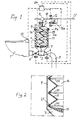
- the vacuum toilet system shown is intended for installation in a passenger transport unit such as a railroad car, a bus or the like. Vacuum is generated separately just before each emptying of the toilet bowl.
- the system includes a toilet with a toilet bowl 1 that is connected to a short sewer pipe 3 through a normally-closed sewer valve 2.
- the sewer pipe 3 is in free connection with a portion 7 of variable volume in a chamber 9 and is closed at its downstream end by a valve 4 that separates the short sewer pipe 3 from an extension 5 thereof that leads to a collection tank, an outlet or the like (not shown).
- the inner space of the chamber 9 is divided by a movable rubber membrane 11 into two portions, a portion 7 (which is an unclean portion) and a clean portion 14.
- the vacuum generator of the system is an ejector 8 that extracts air from the clean portion 14 through an evacuation duct 10.
- the ejector 8 is driven by pressurized air received from a compressed air network 17 via a solenoid valve 12.
- the compressed air network 17 is also connected to another solenoid valve 16 operable to pressurize the clean portion 14 of the pressure chamber with compressed air.
- the air feed duct 18 of the ejector is controlled by the valve 12 and the evacuation duct 10 is controlled by a solenoid valve 6.
- the flow duct passing through the valve 16 is provided with a pressure reduction means 16a. All the valves mentioned are remote controlled.
- a flush button 13 arranged at or near the toilet bowl 1 is connected to a control unit 24 that controls the different functions of the system by operating the remote controlled valves of the system.
- a toilet emptying sequence is started by operating the flush button 13. Thereby an impulse is sent to the control unit 24 which opens the valve 12 and allows compressed air to flow through the ejector 8. This creates, in a few seconds, a partial vacuum of approximately 60% of atmospheric pressure (absolute pressure approximately 0,4 bar) in the clean portion 14 of the chamber 9, which moves the membrane 11 upwards to a pressure balance position lla creating essentially the same vacuum in the space portion 7.
- the sewer valve 2 is now rapidly opened and the waste present in the toilet bowl 1 is instantaneously pressed by the atmospheric pressure into the sewer pipe 3. This causes a rise in pressure in the pipe 3 and in the space portion 7, that causes the membrane 11 to move further upwards to a position 11b. This second movement will be faster and more positive if the ejector 8 is still operating during this phase.
- a less favourable alternative is to disconnect the ejector 8 when the maximum vacuum level has been reached and the valves 6 and 16 are kept closed.
- the sewer valve 2 When all the waste has been removed from the toilet bowl 1, the sewer valve 2 is closed and the valve 4 is opened. The sewage present in the pipe 3 and the space portion 7 may now flow into the pipe 5. Further transport of the waste material may be enhanced by pressurizing the portion 14 of the chamber 9.
- An alternative is to provide a pressure spring 19 urging the membrane 11 downwards and/or to use a membrane that itself functions as a pressure spring. In that case pressurizing of the space 7 is obtained merely by closing down the ejector 8 and by keeping the valve 6 open, provided that the ejector 8 allows ambient air to flow into the portion 14 when the ejector is closed down. If this is not possible, another air flow duct must be provided. If the portion 7 is not pressurized, or is pressurized only by means of a spring force, the valve 6 may be totally omitted as well as the valve 16 and its piping.
- a bottom portion 15 of the membrane 11, forming the upper boundary of the space portion 7, is preferably made of thicker material. It may then provide a suitable support for a pressure spring 19 arranged to urge the membrane 11 downwards should such a spring be required.
- Fig. 2 shows how each outer fold of the membrane 11 can be provided with a strengthening ring 20 of steel or some other suitable material. Without such rings, the outer diameter of the folds can decrease during axial expansion of the membrane so that contact between the membrane folds and the wall of the chamber 9 will be lost.
- the rings 20 keep the outer diameter of the folds practically constant.
- the toilet bowl 1 In connection with an emptying sequence, the toilet bowl 1 is provided with a desired amount of rinse liquid for rinsing and cleaning the inner surface of the bowl. This arrangement is not illustrated because it is known art and is not part of the inventive concept.
Landscapes
- Engineering & Computer Science (AREA)
- Health & Medical Sciences (AREA)
- Life Sciences & Earth Sciences (AREA)
- Hydrology & Water Resources (AREA)
- Public Health (AREA)
- Water Supply & Treatment (AREA)
- Aviation & Aerospace Engineering (AREA)
- Separation Using Semi-Permeable Membranes (AREA)
- Sanitary Device For Flush Toilet (AREA)
- Sewage (AREA)
- Casting Or Compression Moulding Of Plastics Or The Like (AREA)
- Control Of Fluid Pressure (AREA)
Claims (10)
- Vakuumabwassersystem mit mindestens einer unratproduzierenden Einheit (1), beispielsweise einer Toilettenschüssel, mit einer Auslaßöffnung und einem normalerweise geschlossenen Abwasserventil (2) nahe der Auslaßöffnung, welches Abwasserventil die Einheit (1) direkt an das stromaufwärtige Ende einer kurzen Abwasserleitung (3) anschließt, die an ihrem stromabwärtigen Ende ein anderes normalerweise geschlossenes Ventil (4) besitzt und zwischen den Ventilen (2, 4) in Verbindung mit einer Kammer (7) von variablem Volumen ist, welche Kammer zusammen mit der Abwasserleitung (3) mit einer Vorrichtung versehen ist, darin, wenn die Ventile (2, 4) geschlossen sind, ein partielles Vakuum in einer derartigen Größenordnung zu erzeugen, daß Unrat von der Einheit (1) in einer kurzandauernden Weise durch den Druck der Umgebungsluft in die Abwasserleitung (3) gedrückt wird, wenn das Abwasserventil (2) geöffnet ist,
dadurch gekennzeichnet, daß die Vorrichtung zur Erzeugung des partiellen Vakuums eine Druckkammer (9) umfaßt, die durch eine flexible, darin bewegliche Membran (11) in zwei voneinander separierte Anteile (7, 14) unterteilt ist, von denen ein erster Anteil (7) die Kammer mit variablem Volumen bildet, die an die Abwasserleitung (3) angeschlossen ist, und ein zweiter Anteil (14) auf der gegenüberliegenden Seite der Membran (11) eine druckbetriebene Kammer (14) bildet, die an eine Vorrichtung (8) zum Variieren des Druckes darin angeschlossen ist, welche Vorrichtung (8), wenn die Ventile (2, 4) geschlossen sind, eine Reduzierung des Arbeitsdruckes auf ein partielles Vakuum in dem zweiten Anteil (14) zum Bewegen der Membran (11) in eine Druckausgleichsstellung zuläßt, die grundlegend durch die über die gegenüberliegenden Seiten der Membran (11) vorherrschende Druckdifferenz bestimmt ist, wodurch in dem ersten Anteil (7) der Druckkammer und in der Abwasserleitung (3) ein zum Transportieren von Unrat von der unratproduzierenden Einheit (1) ausreichendes partielles Vakuum erzeugt wird, und darüber hinaus in einer darauffolgenden Phase eine Zunahme des Arbeitsdruckes erlaubt, wenn das Abwasserventil (2) geschlossen ist und das andere Ventil (4) an dem stromabwärtigen Ende der Abwasserleitung (3) geöffnet ist, wodurch die Membran (11) in Richtung ihrer Anfangsposition zurück bewegt wird, wodurch, wenn die Membran belastet ist, ein Überdruck in der Abwasserleitung (3) erzeugt wird zur Verbesserung des weiteren Transports von Unrat in der Abwasserleitung (3) mittels dieses Überdrucks. - System gemäß Anspruch 1,
dadurch gekennzeichnet, daß wenn die Membran (11) in ihrer Druckausgleichsstellung ist, ein freier Raumanteil (14) an der Arbeitsdruckseite der Membran existiert, der eine Bewegung der Membran (11) in eine Richtung zuläßt, die den ersten Anteil (7) der Druckkammer vergrößert, wenn der Druck in dem ersten Anteil (7) unter dem Einfluß von in die Abwasserleitung (3) eintretendem Unrat und eintretender Luft steigt, während das Abwasserventil (2) geöffnet ist. - System gemäß Anspruch 1 oder 2,
dadurch gekennzeichnet, daß die Membran (11) einen Bewegungsfreiraum besitzt, welcher Volumenänderungen in der Druckkammer (9) auf jeder Seite der Membran (11) in dem Bereich von 2 bis 15 Litern, vorzugsweise 5 bis 10 Litern zuläßt. - System gemäß einem der vorangehenden Ansprüche,
dadurch gekennzeichnet, daß die Vorrichtung, die den Druck zur Betätigung der Membran schafft, eine Vorrichtung (8) zur Schaffung eines partiellen Vakuums umfaßt, welche Vorrichtung (8) zumindest für im wesentlichen die gesamte Zeit in Betrieb ist, in der das Abwasserventil (2) geöffnet ist, und vorzugsweise angeordnet ist, den auf die Membran (11) wirkenden Arbeitsdruck auf zumindest etwa den halben Druck der Umgebungsluft zu vermindern. - System gemäß einem der vorangehenden Ansprüche,
dadurch gekennzeichnet, daß die Vorrichtung (8) zum Erzeugen eines partiellen Vakuums in der Abwasserleitung (3) angeordnet ist, unmittelbar vor jeder erwünschten Leerung der Einheit (1) aktiviert zu werden. - System gemäß einem der vorangehenden Ansprüche,
dadurch gekennzeichnet, daß das System einen luftbetriebenen Ejektor (8) als Quelle des partiellen Vakuums umfaßt. - System gemäß einem der vorangehenden Ansprüche,
dadurch gekennzeichnet, daß die Membran die Form eines gefaltenen Balges (11) hat, der sich axial in einer im wesentlichen zylindrischen Druckkammer (9) bewegt, wobei die Falten des Balges vorzugsweise durch den Kontakt mit der zylindrischen Innenwand der Druckkammer (9) eine Führung erhalten. - System gemäß Anspruch 7,
dadurch gekennzeichnet, daß zumindest einige der nach außen gerichteten Falten des Balges (11) mit Versteifungsringen (20) oder dergleichen versehen sind, die bewirken, daß der Außendurchmesser der Falten im wesentlichen während der Bewegung des Balges konstant bleibt. - System gemäß Anspruch 7 oder 8,
dadurch gekennzeichnet, daß der Balg an seinem beweglichen Ende stirnseitig zu dem ersten Anteil (7) der Druckkammer mit einer flexiblen peripheren Lippe (21) versehen ist, die an der Innenwand der Druckkammer (9) gleitet. - System gemäß einem der vorangehenden Ansprüche,
dadurch gekennzeichnet, daß die Membran (11) ihrerseits als ein Federglied wirkt, oder durch ein Federglied (19) belastet wird in eine Richtung zu dem ersten Anteil (7) der Druckkammer, wodurch darin und in der Abwasserleitung (3) ein Überdruck erzeugt wird, wenn der auf die Membran (11) wirkende Arbeitsdruck gleich oder annähernd gleich dem Druck der Umgebungsluft ist.
Priority Applications (4)
| Application Number | Priority Date | Filing Date | Title |
|---|---|---|---|
| DK95306394T DK0763633T3 (da) | 1995-09-13 | 1995-09-13 | Membranstyret vakuumkloaksystem |
| EP95306394A EP0763633B1 (de) | 1995-09-13 | 1995-09-13 | Von einer Membran reguliertes Vakuumabwassersystem |
| AT95306394T ATE183795T1 (de) | 1995-09-13 | 1995-09-13 | Von einer membran reguliertes vakuumabwassersystem |
| DE69511695T DE69511695T2 (de) | 1995-09-13 | 1995-09-13 | Von einer Membran reguliertes Vakuumabwassersystem |
Applications Claiming Priority (1)
| Application Number | Priority Date | Filing Date | Title |
|---|---|---|---|
| EP95306394A EP0763633B1 (de) | 1995-09-13 | 1995-09-13 | Von einer Membran reguliertes Vakuumabwassersystem |
Publications (2)
| Publication Number | Publication Date |
|---|---|
| EP0763633A1 EP0763633A1 (de) | 1997-03-19 |
| EP0763633B1 true EP0763633B1 (de) | 1999-08-25 |
Family
ID=8221320
Family Applications (1)
| Application Number | Title | Priority Date | Filing Date |
|---|---|---|---|
| EP95306394A Expired - Lifetime EP0763633B1 (de) | 1995-09-13 | 1995-09-13 | Von einer Membran reguliertes Vakuumabwassersystem |
Country Status (4)
| Country | Link |
|---|---|
| EP (1) | EP0763633B1 (de) |
| AT (1) | ATE183795T1 (de) |
| DE (1) | DE69511695T2 (de) |
| DK (1) | DK0763633T3 (de) |
Cited By (2)
| Publication number | Priority date | Publication date | Assignee | Title |
|---|---|---|---|---|
| US8490223B2 (en) | 2011-08-16 | 2013-07-23 | Flow Control LLC | Toilet with ball valve mechanism and secondary aerobic chamber |
| EP3699088B1 (de) * | 2019-02-19 | 2023-08-09 | B/E Aerospace, Inc. | Vakuumabfallsystem |
Families Citing this family (7)
| Publication number | Priority date | Publication date | Assignee | Title |
|---|---|---|---|---|
| FI105120B (fi) * | 1998-12-23 | 2000-06-15 | Evac Int Oy | Jätteen kuljetusjärjestelmä |
| WO2002059432A1 (de) | 2001-01-26 | 2002-08-01 | Geberit Technik Ag | Toilettenanlage mit einer toilettenschüssel |
| FI110536B (fi) * | 2001-06-21 | 2003-02-14 | Evac Int Oy | Menetelmä jäteaineen kuljettamiseksi alipaineviemärijärjestelmässä |
| DE20301649U1 (de) * | 2003-02-03 | 2004-06-17 | Evac Gmbh | Vakuumtoilette |
| FI118231B (fi) * | 2006-01-30 | 2007-08-31 | Evac Int Oy | Alipaineviemärijärjestelmä |
| JP6034076B2 (ja) * | 2012-06-19 | 2016-11-30 | 福島 寿蔵 | 簡易便槽タンクと汚水回収システム |
| EP3321439A1 (de) | 2016-11-15 | 2018-05-16 | Alte Technologies S.L.U. | Abfalltransportsystem für eine toilette eines öffentlichen verkehrsmittels |
Family Cites Families (7)
| Publication number | Priority date | Publication date | Assignee | Title |
|---|---|---|---|---|
| US2865028A (en) * | 1955-10-04 | 1958-12-23 | Verne L Patenaude | Sewage system for mobile homes and the like |
| US4184506A (en) | 1973-12-29 | 1980-01-22 | Krister Nordberg | Vacuum sewer system |
| SE389882B (sv) | 1975-04-23 | 1976-11-22 | Ifoe Ab | Anordning vid vakuumklosett med uppsamlingsbehallare |
| FI66670C (fi) | 1978-08-25 | 1985-02-01 | Waertsilae Oy Ab | Avloppssystem |
| FR2516119A1 (fr) * | 1981-11-06 | 1983-05-13 | Soterkenos Sarl | Installation d'ecoulement d'un fluide notamment pour l'evacuation des eaux usees |
| DE9111247U1 (de) * | 1991-09-11 | 1992-04-23 | Semco A/S c/o Semco Odense A/S, Odense | Toilettensystem |
| SE469832B (sv) | 1992-02-05 | 1993-09-27 | Evac Ab | Vakuumtoalettsystem med luktfilter |
-
1995
- 1995-09-13 AT AT95306394T patent/ATE183795T1/de not_active IP Right Cessation
- 1995-09-13 EP EP95306394A patent/EP0763633B1/de not_active Expired - Lifetime
- 1995-09-13 DE DE69511695T patent/DE69511695T2/de not_active Expired - Fee Related
- 1995-09-13 DK DK95306394T patent/DK0763633T3/da active
Cited By (2)
| Publication number | Priority date | Publication date | Assignee | Title |
|---|---|---|---|---|
| US8490223B2 (en) | 2011-08-16 | 2013-07-23 | Flow Control LLC | Toilet with ball valve mechanism and secondary aerobic chamber |
| EP3699088B1 (de) * | 2019-02-19 | 2023-08-09 | B/E Aerospace, Inc. | Vakuumabfallsystem |
Also Published As
| Publication number | Publication date |
|---|---|
| DK0763633T3 (da) | 2000-03-20 |
| ATE183795T1 (de) | 1999-09-15 |
| EP0763633A1 (de) | 1997-03-19 |
| DE69511695D1 (de) | 1999-09-30 |
| DE69511695T2 (de) | 1999-12-23 |
Similar Documents
| Publication | Publication Date | Title |
|---|---|---|
| EP0763633B1 (de) | Von einer Membran reguliertes Vakuumabwassersystem | |
| EP1013838B1 (de) | Abwasser-Abführanlage | |
| JP3100992B2 (ja) | 真空トイレット装置 | |
| JP5519900B2 (ja) | 真空式下水システム | |
| JP3524182B2 (ja) | 真空式下水装置 | |
| JPS6234578B2 (de) | ||
| WO2021251873A1 (en) | A valve arrangement for an industrial dust extractor | |
| EP2143848A1 (de) | Luftabsaugvorrichtung für toilettenablaufkanal | |
| KR100763727B1 (ko) | 진공하수시스템 | |
| US6279176B1 (en) | Low water toilet | |
| CA2032882A1 (en) | Vacuum sewer arrangement | |
| JP3647497B2 (ja) | 弁組立体 | |
| JP2006112057A (ja) | 便器装置 | |
| SE506005C2 (sv) | Membranstyrt vakuumavloppsystem | |
| US4621379A (en) | Flushing operating means for vacuum toilet | |
| JP3619026B2 (ja) | 真空弁強制作動機器及び真空式汚水収集システム | |
| JPH08320075A (ja) | 遮断弁 | |
| KR20010013299A (de) | Toilettenanlage mit unterdruckabsaugung | |
| EP0217185B1 (de) | Spülklappe für eine Flugzeugtoilette | |
| JP2586279B2 (ja) | 真空弁ユニット | |
| AU8082491A (en) | A fluid valve device and a positive-displacement pump | |
| JPH0932950A (ja) | 真空弁 | |
| GB2552561A (en) | Fluid deployment apparatus and method | |
| JPH11294626A (ja) | 真空弁 |
Legal Events
| Date | Code | Title | Description |
|---|---|---|---|
| PUAI | Public reference made under article 153(3) epc to a published international application that has entered the european phase |
Free format text: ORIGINAL CODE: 0009012 |
|
| AK | Designated contracting states |
Kind code of ref document: A1 Designated state(s): AT CH DE DK FR IT LI |
|
| 17P | Request for examination filed |
Effective date: 19970619 |
|
| 17Q | First examination report despatched |
Effective date: 19971013 |
|
| GRAG | Despatch of communication of intention to grant |
Free format text: ORIGINAL CODE: EPIDOS AGRA |
|
| GRAG | Despatch of communication of intention to grant |
Free format text: ORIGINAL CODE: EPIDOS AGRA |
|
| GRAH | Despatch of communication of intention to grant a patent |
Free format text: ORIGINAL CODE: EPIDOS IGRA |
|
| GRAH | Despatch of communication of intention to grant a patent |
Free format text: ORIGINAL CODE: EPIDOS IGRA |
|
| GRAA | (expected) grant |
Free format text: ORIGINAL CODE: 0009210 |
|
| AK | Designated contracting states |
Kind code of ref document: B1 Designated state(s): AT CH DE DK FR IT LI |
|
| REF | Corresponds to: |
Ref document number: 183795 Country of ref document: AT Date of ref document: 19990915 Kind code of ref document: T |
|
| REG | Reference to a national code |
Ref country code: CH Ref legal event code: EP |
|
| ITF | It: translation for a ep patent filed | ||
| REF | Corresponds to: |
Ref document number: 69511695 Country of ref document: DE Date of ref document: 19990930 |
|
| REG | Reference to a national code |
Ref country code: CH Ref legal event code: NV Representative=s name: A. BRAUN, BRAUN, HERITIER, ESCHMANN AG PATENTANWAE |
|
| ET | Fr: translation filed | ||
| REG | Reference to a national code |
Ref country code: DK Ref legal event code: T3 |
|
| PLBE | No opposition filed within time limit |
Free format text: ORIGINAL CODE: 0009261 |
|
| STAA | Information on the status of an ep patent application or granted ep patent |
Free format text: STATUS: NO OPPOSITION FILED WITHIN TIME LIMIT |
|
| 26N | No opposition filed | ||
| PGFP | Annual fee paid to national office [announced via postgrant information from national office to epo] |
Ref country code: DK Payment date: 20020813 Year of fee payment: 8 |
|
| PGFP | Annual fee paid to national office [announced via postgrant information from national office to epo] |
Ref country code: AT Payment date: 20030807 Year of fee payment: 9 |
|
| PGFP | Annual fee paid to national office [announced via postgrant information from national office to epo] |
Ref country code: FR Payment date: 20030811 Year of fee payment: 9 |
|
| PGFP | Annual fee paid to national office [announced via postgrant information from national office to epo] |
Ref country code: CH Payment date: 20030818 Year of fee payment: 9 |
|
| PGFP | Annual fee paid to national office [announced via postgrant information from national office to epo] |
Ref country code: DE Payment date: 20030821 Year of fee payment: 9 |
|
| PG25 | Lapsed in a contracting state [announced via postgrant information from national office to epo] |
Ref country code: DK Free format text: LAPSE BECAUSE OF NON-PAYMENT OF DUE FEES Effective date: 20030930 |
|
| REG | Reference to a national code |
Ref country code: DK Ref legal event code: EBP |
|
| PG25 | Lapsed in a contracting state [announced via postgrant information from national office to epo] |
Ref country code: AT Free format text: LAPSE BECAUSE OF NON-PAYMENT OF DUE FEES Effective date: 20040913 |
|
| PG25 | Lapsed in a contracting state [announced via postgrant information from national office to epo] |
Ref country code: LI Free format text: LAPSE BECAUSE OF NON-PAYMENT OF DUE FEES Effective date: 20040930 Ref country code: CH Free format text: LAPSE BECAUSE OF NON-PAYMENT OF DUE FEES Effective date: 20040930 |
|
| PG25 | Lapsed in a contracting state [announced via postgrant information from national office to epo] |
Ref country code: DE Free format text: LAPSE BECAUSE OF NON-PAYMENT OF DUE FEES Effective date: 20050401 |
|
| REG | Reference to a national code |
Ref country code: CH Ref legal event code: PL |
|
| PG25 | Lapsed in a contracting state [announced via postgrant information from national office to epo] |
Ref country code: FR Free format text: LAPSE BECAUSE OF NON-PAYMENT OF DUE FEES Effective date: 20050531 |
|
| REG | Reference to a national code |
Ref country code: FR Ref legal event code: ST |
|
| PG25 | Lapsed in a contracting state [announced via postgrant information from national office to epo] |
Ref country code: IT Free format text: LAPSE BECAUSE OF NON-PAYMENT OF DUE FEES;WARNING: LAPSES OF ITALIAN PATENTS WITH EFFECTIVE DATE BEFORE 2007 MAY HAVE OCCURRED AT ANY TIME BEFORE 2007. THE CORRECT EFFECTIVE DATE MAY BE DIFFERENT FROM THE ONE RECORDED. Effective date: 20050913 |