EP0763648A1 - Dispositif et procédé de forage - Google Patents
Dispositif et procédé de forage Download PDFInfo
- Publication number
- EP0763648A1 EP0763648A1 EP96660061A EP96660061A EP0763648A1 EP 0763648 A1 EP0763648 A1 EP 0763648A1 EP 96660061 A EP96660061 A EP 96660061A EP 96660061 A EP96660061 A EP 96660061A EP 0763648 A1 EP0763648 A1 EP 0763648A1
- Authority
- EP
- European Patent Office
- Prior art keywords
- drilling apparatus
- guiding element
- drill bit
- drilling
- bit assembly
- Prior art date
- Legal status (The legal status is an assumption and is not a legal conclusion. Google has not performed a legal analysis and makes no representation as to the accuracy of the status listed.)
- Withdrawn
Links
Images


Classifications
-
- E—FIXED CONSTRUCTIONS
- E21—EARTH OR ROCK DRILLING; MINING
- E21B—EARTH OR ROCK DRILLING; OBTAINING OIL, GAS, WATER, SOLUBLE OR MELTABLE MATERIALS OR A SLURRY OF MINERALS FROM WELLS
- E21B7/00—Special methods or apparatus for drilling
- E21B7/28—Enlarging drilled holes, e.g. by counterboring
-
- E—FIXED CONSTRUCTIONS
- E21—EARTH OR ROCK DRILLING; MINING
- E21B—EARTH OR ROCK DRILLING; OBTAINING OIL, GAS, WATER, SOLUBLE OR MELTABLE MATERIALS OR A SLURRY OF MINERALS FROM WELLS
- E21B10/00—Drill bits
- E21B10/36—Percussion drill bits
- E21B10/40—Percussion drill bits with leading portion
Definitions
- the present invention relates to a drilling device, by which an existing underground pipe is drilled or renovated and which is of the type presented by the preamble portion of appended claim 1.
- the invention relates also to a method presented in the preamble portion of appended claim 8.
- a guiding element attached on the front side of the percussive drill bit assembly is movable in accordance with the percussive movement of the drill bit and causes inconvenience in the steering operations of the apparatus.
- Such a solution is known for example through international publication WO 95/22677.
- the purpose of the present invention is to eliminate this problem and to provide a drilling apparatus, which is more reliable in operation.
- the drilling apparatus according to the invention is mainly characterized by what is presented in the characterizing portion of appended claim 1.
- the guiding element is attached to a structure, with respect to which the percussive drill bit assembly is movable for effecting the percussive movement. Between the guiding element located in front of the percussive drill bit and the drill bit itself there is the possibility of relative movement in axial direction.
- the guiding element can be connected to the body ot the drilling apparatus and led in axial direction to the front side of the percussive drill bit assembly in such a manner that said element does not impact together with the impact movement of the drill bit.
- the element led axially through the percussive drill bit can be formed in a variety of ways. Most preferably it can be formed so that a tube or rod passing axially through the percussive drill bit is led to the body of the drilling apparatus.
- the element passing axially through the percussive drill bit, a solid rod or a tube containing a channel, is most preferably joined fixedly to the body of the drilling apparatus, that is, it is not movable with respect to the body, which in turn forms the support for the impact force of the movable drill bit.
- the element can be joined to the body also axially movable to some extent, but also in this case the movement of the guiding element is not dependent on the percussive movement of the drill bit assembly, but it moves to the drilling direction in accordance with the advancing movement of the body.
- An impact means reciprocating with respect to the body impacts on the drill bit or drill bit assembly from behind in known manner.
- the method according to the invention is in turn characterized by what is presented in the characterizing portion of appended claim 8.
- the drill bit assembly of the drilling apparatus moves with respect to the guiding element during its percussive movement.
- the forces needed by the drilling apparatus or part thereof are supplied in usual manner at the rear part of the drilling apparatus, in which case via the guiding element not capable of impacting, a part or none of the forces needed by the drilling apparatus are supplied.
- drilling apparatus body is a coherent part containing an impacting piston and having a drill bit mounted thereon and being movable in the direction of the pipe to be renovated
- impact tool means the body and the drill bit mounted thereon
- drill bit assembly means a part performing the percussive movement in the foremost position with respect to the body and constituted of one piece or several interconnected pieces.
- Fig. 1 shows the present prior art presenting an impact tool operable by a medium.
- the impact tool comprises a body 1 containing a work space 1a for the pressurized medium needed by the impact force as well as a piston 1b moved by the medium and arranged to transmit the movement to the percussive drill bit assembly 2 movable with respect to the body, as well as a guiding element 3 coupled to the percussive drill bit assembly.
- the guiding element 3 can be coupled in many ways to the impacting drill bit assembly 2, however, in a manner that the guiding element 3 would not tend to break in advance the pipe system to be drilled, but it would move along inside it and guide the following drill bit assembly 2, which laterally (in radial direction) extends wider than the guiding element 3, in the figure to the location of the walls of the old pipe designated by dot and dash lines in the figure, and it crushes the walls by its percussive movement. If the guiding element 3 has the percussion ability, it is likely to break the pipe system to be renovated and is unable to center the percussive drill bit assembly 2 and keep the drilling apparatus aligned with the pipe line to be renovated.
- the forces needed by the drilling apparatus of Fig. 1 are supplied along a drill string 5 from the start direction of the drilling apparatus. These forces include the rotation and force of advancement (push) needed by the drilling apparatus, and the medium needed for the drive of the drilling apparatus.
- Fig. 2 shows a drilling apparatus according to the invention, consisting of an impact tool including a body 1 of the drilling apparatus containing a work space 1a and a piston 1b movable with respect thereto.
- a percussive drill bit assembly 2 movable with respect to the body 1 is provided in the impact tool.
- a guiding element 3 departing from the impact tool and led through the percussive drill bit is provided in the drilling apparatus.
- the guiding element 3 has the capability of axial movement with respect to the percussive drill bit assembly 2, and it moves together with the body 1 as one kinetic entity to the advancing direction, whereby transmission of impacting forces to the guiding element 3 is avoided.
- the duct 4 for pressurized medium needed by the impact tool.
- the medium is supplied along the duct further into the body 1 via an element 13 disposed in the rear part of the body.
- the duct is passed axially through the drill bit assembly 2, through the piston 1b and through the work space la down to the distribution element 13 located in the rear part of the body and serving for attachment for a tubular piece forming the outer shell of the body.
- the tubular piece has been attached to the element by screwing an inner threading in its rear part over an outer threading disposed around the distribution element. From this distribution element channels open to the work space 1a, where the piston 1b is moved back and forth according to a principle known as such.
- the guiding element 3 is led through a bore formed in the drill bit assembly 2.
- the annular drilling region of the drill bit assembly surrounding the lead-in place on the front face and positioned substantially perpendicularly to the advancing direction and impacting on the end face of the pipe to be renovated, will receive its impact energy from the common piston 1b movable with respect to the body.
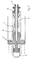
- Fig. 3 shows the invention and its realization, which consists of the impact tool comprising the body 1 and percussive drill bit assembly 2.
- the drilling apparatus has further the guiding element 3.
- the percussive drill bit assembly in turn consists of a ring bit 7a or 7b, inner bit 7c and a drill bit collar, which can be integral with the inner bit.
- the ring bit is the outermost changeable annular piece of the circular drill bit assembly 2, and it can be used to adapt the drill bit diameter to the diameter of the pipeline or tunnel to be drilled.
- reference signs 7a, 7b denote different shapes of the ring bit related to flow alternatives of drill cuttings.
- the guiding element 3 shown in the figure is capable of moving axially with respect to the percussive drill bit assembly 2, and thus is unable to transmit impact forces. Because the guiding element 3 is connected to the body 1 of the impact tool to be immobile with respect thereto during the advancing movement, the impact tool can be supplied with the needed forces along the guiding element, such forces including the force for advancement, rotation, and the medium needed by the impact tool, all from the direction of travel of the drilling apparatus. These forces are transferred to the front end of the guiding element 3 for example along a drill string 5 connected through threading, further to the guiding element 3 and therefrom to the impact tool.
- a radially wider centering element 6 is coupled to the guiding element 3, most preferably in such a manner that it is capable of moving axially with respect to the guiding element 3, thus having smallest possible tendency to break the pipe system to be renovated.
- the centering element 6 can be constructed freely rotatable or rotatable together with the guiding element 3. Its possible stroke length in relation to the guiding element 3 can be dimensioned in such a fashion that if it for example gets stuck in the pipe to be renovated, the impacting drill bit assembly will be able to release it.
- the arrows shown in the figure show the direction of travel of the flushing medium and drill cuttings. The arrows in the upper part of the figure represent the forward movement of the drill cuttings, whereas the arrows in the lower part represent their movement backwards. The drill cuttings can also be led to both directions at the same time.
- the percussive drill bit assembly shown in the figure consisting of the inner bit 2 and the ring bit 7a or 7b, is coupled at the outer edge through a rotation coupling to a protective tube 14 surrounding the body 1, the coupling being made in a manner that it is also capable of moving axially to some extent by virtue of axial clearance between the drill bit assembly and protective tube.
- a pipe 12 to be installed which for example can be pushed from behind or pulled with the drilling apparatus itself, the pipe being in the latter case attached to the body 1 of the drilling apparatus.
- both the apparatus and pipes mounted at its rear portion can be pulled, and in case of heavier pipes the apparatus is both pulled from the direction of the drill string and the pipes to be installed are pushed from behind concurrently with the advancement of the drilling apparatus.
- the attachment of the guiding element 3 to the impact tool itself takes place through a part 13 located in the rear end of the body 1 in a manner that it further transmits the forces to the impact tool.
- the attachment can be arranged in a variety of ways, and the figure represents only one possibility.
- the outlet openings of the medium of the impact tool, denoted in the figure by reference numerals 8 and 10, as well as the guiding passages 8 and 11 for the drill cuttings can be arranged in various ways. In the upper part of Fig.
- a channel 8 for flushing medium introduced through the drill bit assembly 2 opens to the impact surface of the drill bit, which channel further urges the drill cuttings through the hollow interior part 9 of the centering element 6 to the front side thereof.
- a channel 10 opens to the impact surface of the drill bit, and in radial direction in an outer position therefrom, a channel 11 is passed through the drill bit assembly 2, for example through the ring bit 7b. Through this channel the cuttings are pushed into a space between the protective tube 14 and the body 1, wherefrom it is led backwards. In both cases the waste can be removed with a screw introduced from the front or from behind forwards or backwards, respectively, or with another discharge method, for example suction.
- Fig. 4 shows a possible embodiment of the invention, if the forces for the impact tool, such as advancing movement and rotation as well as the medium are supplied from the departing direction of the drilling apparatus through the drill string 5 shown in the figure to the impact tool via the element 13 in the rear end of the body 1.
- the guiding element 3 is consequently not made to feed for example pressurized medium, it can be closed at its end (as shown in the figure), because it is now used only for the point of attachment of the centering element 6.
- the guiding element 3 is capable of moving axially with respect to the percussive drill bit assembly 2, which also in this construction consists of a ring bit 7a or 7b and the inner bit 7c. Also in this construction there is the possibility to supply one or several forces required by the operation of the apparatus through the guiding element 3, such as the advancing movement (traction).
- centering element 6 In the guiding element 3, which is supported by the body 1 of the drilling apparatus, there is in radial direction (in a direction perpendicular to the longitudinal direction of the pipe to be drilled) wider centering element 6, which, as mentioned hereinabove, can be freely rotating or provided for rotation together with the guiding element 3.
- the centering element 6 can be dimensioned according to the inner diameter of the pipe to be drilled away, and it can also be arranged releasable from the guiding element and replaceable with a new one, always according to the pipe size.
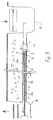
- Fig. 5 shows a case where the principle of operation is the same as in the embodiment of Fig. 3.
- the centering element 6 is formed of a conveyor moving the drill cuttings forward to the drilling direction, the conveyor thus being provided around the guiding element 3.
- the conveyor is a helical conveyor screw attached around the guiding element 3 containing the duct 4 for the medium.
- the screw winds around the element 3 in a helical manner and is provided for rotation together With the rotational movement of the guiding element.
- Similar helical screws exist also in successive sections 5a of the drill string 5 fixed on the front side of the element, which in a way form the forwardly directed extensions of the guiding element 3 attached to the body 1.
- the widths of the helical screws can vary along the conveyor screw system thus formed within the pipe to be drilled, and the helical screws closer to the body 1 are preferably wider.
- the width of the helical screws is also dimensioned according to the pipe sizes. It is also possible that the guiding element 3 passed through the drill bit assembly 2 is so short that it does not have a helical screw, and the first helical screw is disposed in the first section of the drill string 5 that is to be joined to the guiding element.
- the discharge of the drill cuttings consisting mainly of the old pipe and produced by the drill bit assembly 2 forwards into the drilling direction is advantageous, because there is no need to guide it past the body of the drilling apparatus behind, but it can be conveyed right from the place it is produced forwards along the still intact pipe.
- the conveyor construction most preferably a conveyor screw type element, forms at the same time a construction that guides and centers well the drilling apparatus within the pipe.
- Fig. 5 shows also the drilling principle.
- the body 1 of the drilling apparatus is in the start shaft, and in the finish shaft sections 5a of the drill string 5, equipped with helical conveyor screws, are joined end-to-end together and fed along the pipe backwards until their rear end reaches the start shaft B, where they are connected to the body 1.
- new pipe sections forming the pipe to be installed in the place of the old pipe are fed one after the other after the body 1 of the drilling apparatus, the feeding being performed concurrently according to the advancement of the drilling from the start shaft A towards the finish shaft B, and simultaneously drill string sections 5a are taken away.
- Both the supply of the pressurized medium and the moving force required by the drilling apparatus can be provided by a machine located in the finish shaft B, the machine being in this case a traction and rotation unit, analogical to previously known pushing and rotation units.
- the force of movement can be alternatively transmitted additionally or solely from behind by means of drill string sections fed after the body 1 within the new pipe from the start shaft A.
- a rotation and pushing unit located in the start shaft A is utilized.
- the pressurized medium can be fed, in which case the solution resembles that of Fig. 4 with the difference that also in this case the above-mentioned drill string sections 5a having the helical screw conveying the drill cuttings forward act as the centering structure.
- the drilling apparatus is, however, such that both the rotative and tractive force are introduced from the front, that is, through the existing pipe, whereby through the rotative movement of the drill string 5 and by virtue of the helical screw structure forming a kinetic entity therewith, also the conveying of the cuttings forwards will be possible.
- the pressurized medium required by the percussive action such as pressure air, is most preferably supplied through the drill string 5 as well. If some of the forces needed by said drilling apparatus must be brought from behind, it is most advantageously the pressure air causing the percussive movement, because the compressor needed for its feeding does not take much space in the start shaft either.
- the invention is not restricted to the arrangements shown in the figures for supply and distribution of the pressurized medium for effecting the impacting movement, but it can use all arrangements known in the art.
- air acts as a pressurized medium, and it can thus be used also for flushing, but the invention can be applied also to cases where the medium is hydraulic and it possibly has a separate return channel and the flushing medium has a channel of its own.
Landscapes
- Engineering & Computer Science (AREA)
- Life Sciences & Earth Sciences (AREA)
- Geology (AREA)
- Mining & Mineral Resources (AREA)
- Physics & Mathematics (AREA)
- Environmental & Geological Engineering (AREA)
- Fluid Mechanics (AREA)
- General Life Sciences & Earth Sciences (AREA)
- Geochemistry & Mineralogy (AREA)
- Mechanical Engineering (AREA)
- Earth Drilling (AREA)
Priority Applications (2)
| Application Number | Priority Date | Filing Date | Title |
|---|---|---|---|
| CA 2214175 CA2214175A1 (fr) | 1996-09-13 | 1997-09-09 | Foreuse et methode de remise a neuf des tuyaux souterrains |
| AU36873/97A AU3687397A (en) | 1996-09-13 | 1997-09-09 | Drilling apparatus and drilling method for renovating underground pipes |
Applications Claiming Priority (2)
| Application Number | Priority Date | Filing Date | Title |
|---|---|---|---|
| FI954309 | 1995-09-14 | ||
| FI954309A FI954309A7 (fi) | 1995-09-14 | 1995-09-14 | Poralaite ja porausmenetelmä |
Publications (1)
| Publication Number | Publication Date |
|---|---|
| EP0763648A1 true EP0763648A1 (fr) | 1997-03-19 |
Family
ID=8544016
Family Applications (1)
| Application Number | Title | Priority Date | Filing Date |
|---|---|---|---|
| EP96660061A Withdrawn EP0763648A1 (fr) | 1995-09-14 | 1996-09-13 | Dispositif et procédé de forage |
Country Status (3)
| Country | Link |
|---|---|
| US (1) | US5791419A (fr) |
| EP (1) | EP0763648A1 (fr) |
| FI (1) | FI954309A7 (fr) |
Cited By (2)
| Publication number | Priority date | Publication date | Assignee | Title |
|---|---|---|---|---|
| EP1098065A1 (fr) * | 1999-11-02 | 2001-05-09 | VISSER & SMIT HANAB B.V. | Procédé de creusement d'un tunnel |
| EP1300543A1 (fr) * | 2001-10-08 | 2003-04-09 | Günter W. Prof. Dr. Klemm | Système de forage avec élargisseur |
Families Citing this family (66)
| Publication number | Priority date | Publication date | Assignee | Title |
|---|---|---|---|---|
| FI96356C (fi) * | 1994-12-13 | 1999-12-18 | Valto Ilomaeki | Porausmenetelmä ja teräasetelma menetelmän toteuttamiseksi |
| US6575240B1 (en) | 1998-12-07 | 2003-06-10 | Shell Oil Company | System and method for driving pipe |
| US6823937B1 (en) | 1998-12-07 | 2004-11-30 | Shell Oil Company | Wellhead |
| US7357188B1 (en) | 1998-12-07 | 2008-04-15 | Shell Oil Company | Mono-diameter wellbore casing |
| US6557640B1 (en) | 1998-12-07 | 2003-05-06 | Shell Oil Company | Lubrication and self-cleaning system for expansion mandrel |
| GB2384502B (en) | 1998-11-16 | 2004-10-13 | Shell Oil Co | Coupling an expandable tubular member to a preexisting structure |
| US7121352B2 (en) | 1998-11-16 | 2006-10-17 | Enventure Global Technology | Isolation of subterranean zones |
| US6604763B1 (en) | 1998-12-07 | 2003-08-12 | Shell Oil Company | Expandable connector |
| US6745845B2 (en) | 1998-11-16 | 2004-06-08 | Shell Oil Company | Isolation of subterranean zones |
| US6712154B2 (en) | 1998-11-16 | 2004-03-30 | Enventure Global Technology | Isolation of subterranean zones |
| US7603758B2 (en) | 1998-12-07 | 2009-10-20 | Shell Oil Company | Method of coupling a tubular member |
| US6640903B1 (en) | 1998-12-07 | 2003-11-04 | Shell Oil Company | Forming a wellbore casing while simultaneously drilling a wellbore |
| US7231985B2 (en) | 1998-11-16 | 2007-06-19 | Shell Oil Company | Radial expansion of tubular members |
| US6634431B2 (en) | 1998-11-16 | 2003-10-21 | Robert Lance Cook | Isolation of subterranean zones |
| US7363984B2 (en) | 1998-12-07 | 2008-04-29 | Enventure Global Technology, Llc | System for radially expanding a tubular member |
| US6758278B2 (en) | 1998-12-07 | 2004-07-06 | Shell Oil Company | Forming a wellbore casing while simultaneously drilling a wellbore |
| GB2356651B (en) | 1998-12-07 | 2004-02-25 | Shell Int Research | Lubrication and self-cleaning system for expansion mandrel |
| US7552776B2 (en) | 1998-12-07 | 2009-06-30 | Enventure Global Technology, Llc | Anchor hangers |
| US7185710B2 (en) | 1998-12-07 | 2007-03-06 | Enventure Global Technology | Mono-diameter wellbore casing |
| GB2344606B (en) | 1998-12-07 | 2003-08-13 | Shell Int Research | Forming a wellbore casing by expansion of a tubular member |
| US7195064B2 (en) | 1998-12-07 | 2007-03-27 | Enventure Global Technology | Mono-diameter wellbore casing |
| AU770359B2 (en) | 1999-02-26 | 2004-02-19 | Shell Internationale Research Maatschappij B.V. | Liner hanger |
| US7055608B2 (en) | 1999-03-11 | 2006-06-06 | Shell Oil Company | Forming a wellbore casing while simultaneously drilling a wellbore |
| FI990589L (fi) * | 1999-03-16 | 2000-09-17 | Rd Trenchless Ltd Oy | Menetelmä ja laitteisto maanalaiseen poraukseen |
| CA2306656C (fr) * | 1999-04-26 | 2006-06-06 | Shell Internationale Research Maatschappij B.V. | Connexion extensible |
| US7350563B2 (en) | 1999-07-09 | 2008-04-01 | Enventure Global Technology, L.L.C. | System for lining a wellbore casing |
| DE19946587A1 (de) * | 1999-09-29 | 2001-04-12 | Eurodrill Gmbh Consulting Engi | Vorrichtung zum Richtungsbohren |
| AU783245B2 (en) | 1999-11-01 | 2005-10-06 | Shell Internationale Research Maatschappij B.V. | Wellbore casing repair |
| EG22306A (en) | 1999-11-15 | 2002-12-31 | Shell Int Research | Expanding a tubular element in a wellbore |
| US7234531B2 (en) | 1999-12-03 | 2007-06-26 | Enventure Global Technology, Llc | Mono-diameter wellbore casing |
| GB0010212D0 (en) * | 2000-04-26 | 2000-06-14 | Euro Iseki Ltd | Backreaming tool |
| US7100684B2 (en) | 2000-07-28 | 2006-09-05 | Enventure Global Technology | Liner hanger with standoffs |
| AU9269501A (en) | 2000-09-18 | 2002-03-26 | Shell Oil Co | Liner hanger with sliding sleeve valve |
| WO2002053867A2 (fr) | 2001-01-03 | 2002-07-11 | Enventure Global Technology | Cuvelage de diamètre nanométrique pour puits foré |
| GB2389597B (en) | 2000-10-02 | 2005-05-18 | Shell Oil Co | Plastically deforming and radially expanding a tubular member |
| US7100685B2 (en) | 2000-10-02 | 2006-09-05 | Enventure Global Technology | Mono-diameter wellbore casing |
| US7410000B2 (en) | 2001-01-17 | 2008-08-12 | Enventure Global Technology, Llc. | Mono-diameter wellbore casing |
| GB2395506B (en) | 2001-07-06 | 2006-01-18 | Eventure Global Technology | Liner hanger |
| CA2453063C (fr) | 2001-07-06 | 2011-03-22 | Enventure Global Technology | Suspension de colonne perdue |
| US7258168B2 (en) | 2001-07-27 | 2007-08-21 | Enventure Global Technology L.L.C. | Liner hanger with slip joint sealing members and method of use |
| US7793721B2 (en) | 2003-03-11 | 2010-09-14 | Eventure Global Technology, Llc | Apparatus for radially expanding and plastically deforming a tubular member |
| WO2003023178A2 (fr) | 2001-09-07 | 2003-03-20 | Enventure Global Technology | Ensemble cone d'expansion reglable |
| GB2422859B (en) | 2001-11-12 | 2006-12-13 | Enventure Global Technology | Collapsible expansion cone |
| AU2002367348A1 (en) | 2001-12-27 | 2003-07-24 | Enventure Global Technology | Seal receptacle using expandable liner hanger |
| WO2003089161A2 (fr) | 2002-04-15 | 2003-10-30 | Enventure Global Technlogy | Manchon protecteur destine aux connexions filetees d'un dispositif de suspension pour colonne de tubage perdue expansible |
| WO2004018824A2 (fr) | 2002-08-23 | 2004-03-04 | Enventure Global Technology | Impulsion magnetique appliquee sur un manchon et procede de formation d'un tubage de puits de forage |
| US7424918B2 (en) | 2002-08-23 | 2008-09-16 | Enventure Global Technology, L.L.C. | Interposed joint sealing layer method of forming a wellbore casing |
| ATE417993T1 (de) | 2002-02-15 | 2009-01-15 | Enventure Global Technology | Bohrlochfutterrohr mit einem einzigen durchmesser |
| EP1985797B1 (fr) | 2002-04-12 | 2011-10-26 | Enventure Global Technology | Manchon protecteur pour connexions filetées pour support de conduite extensible |
| AU2003225001A1 (en) | 2002-05-29 | 2003-12-19 | Eventure Global Technology | System for radially expanding a tubular member |
| GB2418944B (en) | 2002-06-10 | 2006-08-30 | Enventure Global Technology | Mono Diameter Wellbore Casing |
| CA2499071C (fr) | 2002-09-20 | 2014-06-03 | Enventure Global Technology | Mandrin d'extension autolubrifiant pour element tubulaire extensible |
| CA2499007C (fr) | 2002-09-20 | 2012-08-07 | Enventure Global Technology | Bouchon inferieur pour la formation d'un tubage de puits de forage de diametre unique |
| AU2003263859A1 (en) | 2002-09-20 | 2004-04-08 | Enventure Global Technology | Protective sleeve for expandable tubulars |
| WO2004027392A1 (fr) | 2002-09-20 | 2004-04-01 | Enventure Global Technology | Evaluation de formabilite de conduite pour des elements tubulaires extensibles |
| WO2004076798A2 (fr) | 2003-02-26 | 2004-09-10 | Enventure Global Technology | Appareil d'expansion radiale et de deformation plastique d'un element tubulaire |
| US7886831B2 (en) | 2003-01-22 | 2011-02-15 | Enventure Global Technology, L.L.C. | Apparatus for radially expanding and plastically deforming a tubular member |
| US7503393B2 (en) | 2003-01-27 | 2009-03-17 | Enventure Global Technology, Inc. | Lubrication system for radially expanding tubular members |
| GB2415988B (en) | 2003-04-17 | 2007-10-17 | Enventure Global Technology | Apparatus for radially expanding and plastically deforming a tubular member |
| US20050166387A1 (en) | 2003-06-13 | 2005-08-04 | Cook Robert L. | Method and apparatus for forming a mono-diameter wellbore casing |
| US7712522B2 (en) | 2003-09-05 | 2010-05-11 | Enventure Global Technology, Llc | Expansion cone and system |
| GB2432866A (en) | 2004-08-13 | 2007-06-06 | Enventure Global Technology | Expandable tubular |
| CN1769642B (zh) * | 2004-11-05 | 2010-10-06 | 张四清 | 地表浅层打井机 |
| IES20050621A2 (en) * | 2005-09-20 | 2006-11-15 | Minroc Techn Promotions Ltd | A percussion hammer for enlarging drilled holes |
| US7673706B2 (en) * | 2006-03-30 | 2010-03-09 | Sandvik Intellectual Property Ab | Down-the-hole hammer with pilot and method of enlarging a hole |
| CN104595578A (zh) * | 2015-01-16 | 2015-05-06 | 天津穿越工程技术有限公司 | 一种室内管道更新方法 |
Citations (13)
| Publication number | Priority date | Publication date | Assignee | Title |
|---|---|---|---|---|
| GB224967A (en) * | 1923-08-24 | 1924-11-24 | Emil Schweitzer | Improvements in or connected with apparatus for boring earth and rock for use in mines and the like |
| US3491843A (en) * | 1966-04-01 | 1970-01-27 | Jose Molina Rodriguez | Mechanism for widening galleries applicable to drilling machines |
| US3910361A (en) * | 1972-11-15 | 1975-10-07 | Boehler & Co Ag Geb | Apparatus for drilling and enlarging a bore |
| US4020641A (en) * | 1975-12-22 | 1977-05-03 | Kabushiki Kaisha Komatsu Seisakusho | Method of laying pipes in the ground |
| US4024721A (en) * | 1974-05-23 | 1977-05-24 | Kabushiki Kaisha Komatsu Seisakusho | Method and apparatus for laying pipes in the ground |
| US4456078A (en) * | 1980-10-23 | 1984-06-26 | Adam Arthur J L | Earth boring method and apparatus |
| US4840235A (en) * | 1988-04-14 | 1989-06-20 | Roger Masse | Impact hammer assembly for drilling rock |
| US4878547A (en) * | 1988-10-28 | 1989-11-07 | Ingersoll-Rand Company | Rock drilling apparatus |
| EP0342246A1 (fr) * | 1988-05-12 | 1989-11-23 | Kabushiki Kaisha Iseki Kaihatsu Koki | Méthode de rénovation d'une tuyauterie existante et dispositif pour cela |
| US5090487A (en) * | 1991-02-22 | 1992-02-25 | Masse Roger F | Drill head with integral impact hammers |
| EP0507610A1 (fr) * | 1991-04-04 | 1992-10-07 | Ian Graeme Rear | Marteau pour le forage en remontant |
| WO1995012747A1 (fr) * | 1993-11-05 | 1995-05-11 | Nacap Nederland B.V. | Procede et systeme de recherche et d'extraction de matieres premieres, de minerais ou analogue dans un sol meuble |
| WO1995022677A1 (fr) | 1994-02-21 | 1995-08-24 | Ilomaeki Valto | Equipement de percement de tunnel et procede de percement |
Family Cites Families (9)
| Publication number | Priority date | Publication date | Assignee | Title |
|---|---|---|---|---|
| CA832325A (en) * | 1970-01-20 | Molina Rodriguez Jose | Mechanism for widening galleries, applicable to drilling machines | |
| US4043136A (en) * | 1975-07-14 | 1977-08-23 | Tidril Corporation | System and method for installing production casings |
| GB1572253A (en) * | 1977-01-06 | 1980-07-30 | Komatsu Mfg Co Ltd | Excavating head |
| US4117895A (en) * | 1977-03-30 | 1978-10-03 | Smith International, Inc. | Apparatus and method for enlarging underground arcuate bore holes |
| GB2137720B (en) * | 1983-03-31 | 1987-01-28 | Daly Limited P N | Pipe replacement |
| GB2149472A (en) * | 1983-11-10 | 1985-06-12 | Merstan Impact Moling Limited | Mole |
| US4915543A (en) * | 1988-05-12 | 1990-04-10 | Kabushiki Kaisha Iseki Kaihatsu Koki | Existing pipeline renewing method and apparatus therefor |
| DE3826513A1 (de) * | 1988-08-04 | 1990-02-08 | Schmidt Paul | Verfahren und rammbohrgeraet zum grabenlosen verlegen von versorgungsleitungen |
| JPH06503624A (ja) * | 1991-11-06 | 1994-04-21 | グラネラ, ブルーノ | 特に下水管を交換する方法及びこの方法を実施するための装置 |
-
1995
- 1995-09-14 FI FI954309A patent/FI954309A7/fi unknown
-
1996
- 1996-09-13 US US08/718,001 patent/US5791419A/en not_active Expired - Fee Related
- 1996-09-13 EP EP96660061A patent/EP0763648A1/fr not_active Withdrawn
Patent Citations (13)
| Publication number | Priority date | Publication date | Assignee | Title |
|---|---|---|---|---|
| GB224967A (en) * | 1923-08-24 | 1924-11-24 | Emil Schweitzer | Improvements in or connected with apparatus for boring earth and rock for use in mines and the like |
| US3491843A (en) * | 1966-04-01 | 1970-01-27 | Jose Molina Rodriguez | Mechanism for widening galleries applicable to drilling machines |
| US3910361A (en) * | 1972-11-15 | 1975-10-07 | Boehler & Co Ag Geb | Apparatus for drilling and enlarging a bore |
| US4024721A (en) * | 1974-05-23 | 1977-05-24 | Kabushiki Kaisha Komatsu Seisakusho | Method and apparatus for laying pipes in the ground |
| US4020641A (en) * | 1975-12-22 | 1977-05-03 | Kabushiki Kaisha Komatsu Seisakusho | Method of laying pipes in the ground |
| US4456078A (en) * | 1980-10-23 | 1984-06-26 | Adam Arthur J L | Earth boring method and apparatus |
| US4840235A (en) * | 1988-04-14 | 1989-06-20 | Roger Masse | Impact hammer assembly for drilling rock |
| EP0342246A1 (fr) * | 1988-05-12 | 1989-11-23 | Kabushiki Kaisha Iseki Kaihatsu Koki | Méthode de rénovation d'une tuyauterie existante et dispositif pour cela |
| US4878547A (en) * | 1988-10-28 | 1989-11-07 | Ingersoll-Rand Company | Rock drilling apparatus |
| US5090487A (en) * | 1991-02-22 | 1992-02-25 | Masse Roger F | Drill head with integral impact hammers |
| EP0507610A1 (fr) * | 1991-04-04 | 1992-10-07 | Ian Graeme Rear | Marteau pour le forage en remontant |
| WO1995012747A1 (fr) * | 1993-11-05 | 1995-05-11 | Nacap Nederland B.V. | Procede et systeme de recherche et d'extraction de matieres premieres, de minerais ou analogue dans un sol meuble |
| WO1995022677A1 (fr) | 1994-02-21 | 1995-08-24 | Ilomaeki Valto | Equipement de percement de tunnel et procede de percement |
Cited By (4)
| Publication number | Priority date | Publication date | Assignee | Title |
|---|---|---|---|---|
| EP1098065A1 (fr) * | 1999-11-02 | 2001-05-09 | VISSER & SMIT HANAB B.V. | Procédé de creusement d'un tunnel |
| NL1016496C2 (nl) * | 1999-11-02 | 2001-06-06 | Visser & Smit Bv | Werkwijze voor het aanleggen van een geboorde tunnel. |
| EP1300543A1 (fr) * | 2001-10-08 | 2003-04-09 | Günter W. Prof. Dr. Klemm | Système de forage avec élargisseur |
| US6808030B2 (en) | 2001-10-08 | 2004-10-26 | Klemm Guenter W | Enlargement drilling system |
Also Published As
| Publication number | Publication date |
|---|---|
| FI954309L (fi) | 1997-03-15 |
| FI954309A0 (fi) | 1995-09-14 |
| US5791419A (en) | 1998-08-11 |
| FI954309A7 (fi) | 1997-03-15 |
Similar Documents
| Publication | Publication Date | Title |
|---|---|---|
| US5791419A (en) | Drilling apparatus for replacing underground pipes | |
| US6755593B2 (en) | Pipe replacement method and rotary impact mechanism for pipe bursting | |
| US7055621B2 (en) | Method and apparatus for replacement of underground pipe | |
| EP1540219B1 (fr) | Dispositif et procede pour le remplacement de canalisation souterraine | |
| US5301758A (en) | Method and apparatus for enlarging a bore hole | |
| US6161631A (en) | Environmentally friendly horizontal boring system | |
| AU643707B2 (en) | Drilling apparatus and method for its control | |
| AU2006293487A1 (en) | A percussion hammer for enlarging drilled holes | |
| US6386299B1 (en) | Method and apparatus for reaming pilot hole | |
| US5494116A (en) | Pneumatic impact tool for pipe insertion | |
| EP0209217A2 (fr) | Dispositif et procédé d'exécution d'un forage courbe et d'installation d'une conduite dans ce forage | |
| CA2240770A1 (fr) | Appareil de forage | |
| US7111695B2 (en) | Pneumatic rock-boring device and method for horizontal drilling using compressed air and drilling medium | |
| SE529459C2 (sv) | Borrande apparatur | |
| CN111779453B (zh) | 一种联合式扩孔方法及装置 | |
| CA2534912C (fr) | Dispositif d'eclatement de conduite dote d'un element d'eclatement spherique | |
| EP0746665A1 (fr) | Equipement de percement de tunnel et procede de percement | |
| GB2186899A (en) | Installing pipes in the ground | |
| US4653810A (en) | Pre-bolting system for underground mines | |
| CA2214175A1 (fr) | Foreuse et methode de remise a neuf des tuyaux souterrains | |
| JP2000337079A (ja) | 二重管方式削孔工法及びその装置並びに埋設管押し込みアダプタ | |
| CN118167330B (zh) | 牵引式盾构机 | |
| HK1010236A (en) | Drilling apparatus and drilling method for renovating underground pipes | |
| US2913225A (en) | Rock drilling apparatus | |
| CN1179498A (zh) | 用于更新地下管道的打孔设备和打孔方法 |
Legal Events
| Date | Code | Title | Description |
|---|---|---|---|
| PUAI | Public reference made under article 153(3) epc to a published international application that has entered the european phase |
Free format text: ORIGINAL CODE: 0009012 |
|
| AK | Designated contracting states |
Kind code of ref document: A1 Designated state(s): BE DE FR GB IT NL |
|
| 17P | Request for examination filed |
Effective date: 19970829 |
|
| 17Q | First examination report despatched |
Effective date: 20010122 |
|
| STAA | Information on the status of an ep patent application or granted ep patent |
Free format text: STATUS: THE APPLICATION IS DEEMED TO BE WITHDRAWN |
|
| 18D | Application deemed to be withdrawn |
Effective date: 20020403 |