EP0763662A2 - Compresseur à canal latéral - Google Patents
Compresseur à canal latéral Download PDFInfo
- Publication number
- EP0763662A2 EP0763662A2 EP96114030A EP96114030A EP0763662A2 EP 0763662 A2 EP0763662 A2 EP 0763662A2 EP 96114030 A EP96114030 A EP 96114030A EP 96114030 A EP96114030 A EP 96114030A EP 0763662 A2 EP0763662 A2 EP 0763662A2
- Authority
- EP
- European Patent Office
- Prior art keywords
- housing
- side channel
- channel compressor
- drive motor
- housing halves
- Prior art date
- Legal status (The legal status is an assumption and is not a legal conclusion. Google has not performed a legal analysis and makes no representation as to the accuracy of the status listed.)
- Granted
Links
Images

Classifications
-
- F—MECHANICAL ENGINEERING; LIGHTING; HEATING; WEAPONS; BLASTING
- F04—POSITIVE - DISPLACEMENT MACHINES FOR LIQUIDS; PUMPS FOR LIQUIDS OR ELASTIC FLUIDS
- F04D—NON-POSITIVE-DISPLACEMENT PUMPS
- F04D29/00—Details, component parts, or accessories
- F04D29/60—Mounting; Assembling; Disassembling
- F04D29/601—Mounting; Assembling; Disassembling specially adapted for elastic fluid pumps
-
- F—MECHANICAL ENGINEERING; LIGHTING; HEATING; WEAPONS; BLASTING
- F04—POSITIVE - DISPLACEMENT MACHINES FOR LIQUIDS; PUMPS FOR LIQUIDS OR ELASTIC FLUIDS
- F04D—NON-POSITIVE-DISPLACEMENT PUMPS
- F04D23/00—Other rotary non-positive-displacement pumps
-
- F—MECHANICAL ENGINEERING; LIGHTING; HEATING; WEAPONS; BLASTING
- F04—POSITIVE - DISPLACEMENT MACHINES FOR LIQUIDS; PUMPS FOR LIQUIDS OR ELASTIC FLUIDS
- F04D—NON-POSITIVE-DISPLACEMENT PUMPS
- F04D23/00—Other rotary non-positive-displacement pumps
- F04D23/008—Regenerative pumps
Definitions
- the invention relates to a side channel compressor according to the preamble of claim 1.
- Such a side channel compressor is known from DE-U-77 10 288.
- this known compressor several fastening points are provided distributed over the outer circumference of the housing, to which a base part formed from sheet metal can be fastened by means of screws.
- the foot part itself has fastening tabs projecting laterally over the fastening points on the compressor housing, with which it can be fastened to a mounting surface at the installation location of the compressor.
- the known compressor can only be set up with an axis that is horizontal relative to the mounting surface due to the fastening points provided on the outer circumference of its housing.
- the invention is based on the object of designing a side channel compressor of the generic type in such a way that it can be set up with an axis which is perpendicular to the mounting surface.
- tubular feet are provided as fastening points at least on the outer circumference of the housing half facing away from the drive motor and have a radially projecting stop shoulder for a fastening element in their cavity. Due to the arrangement of the fastening points on the outer circumference on the one hand, there is good accessibility to these points, so that the fastening of the compressor at the installation site is made much easier. On the other hand, the force is introduced into the fastening points in a relatively short way via the outer regions of the housing halves, so that in particular the hub region is kept free of loads which could lead to an impairment of the narrow gaps existing in this region in the case of a side channel compressor. Fastening screws can be passed through the hollow feet and their screw heads rest on the radially projecting stop shoulder and thus hold the housing.
- tubular feet are integrally formed on both housing halves, a similar design of the two housing halves is possible.
- a perfectly identical design of both housing halves results from the fact that the feet are arranged symmetrically with respect to an axial bisection line of the housing halves and are also shaped symmetrically with respect to this halving line.
- a sealing of both housing halves without separate sealing means with identical design of the housing halves is possible in that on the front peripheral edge of the inner front side of each housing half a sealing lip extending on one side of the bisecting line over one circumferential half of the front side and on the other side of the bisecting line extending sealing groove is formed over the other circumferential half.
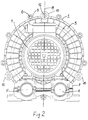
- the housing of a side channel compressor consisting of two housing halves 2 and 3 is designated.
- a drive motor 4 is flanged onto one end of the housing.
- a muffler part 7 having an inlet and an outlet opening 5 and 6 is arranged below the drive motor.
- Certain eyes 9 are provided on the outer circumference of the housing halves 2 and 3 for receiving connecting screws 8.
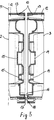
- three tubular feet 10 are integrally formed on the outer circumference of the housing halves 2 and 3. The feet 10 protrude at least slightly in the axial direction relative to the plane 11 of the end face of the housing halves 2 and 3, so that when the compressor unit is installed with a vertical axis, the compressor housing 1 rests with the feet 10 on the installation surface.
- a stop shoulder 13 projecting radially inward is formed in the cavity 12 of the feet 10. On this stop shoulder 13, screws serving to fasten the compressor unit at its installation site rest with their screw heads.
- feet 10 would only be required for fastening the compressor unit on one housing half 2 facing away from the drive motor 4, they are also provided on the other housing half 3.
- the feet 10 are also symmetrical to an axially extending bisecting plane of the Housing halves 2 and 3 arranged and formed symmetrically to this plane when divided by this plane. So that both housing halves 2 and 3 can be made completely identical in terms of their outline.
- openings 14 are provided as knockouts 15 on both housing halves 2 and 3 and are only opened on the other housing half 3.
- the sealing of the two housing halves 2 and 3 takes place via a sealing lip 17 which is provided on the front peripheral edge 16 of the inner end face of each housing half 2 and 3 and extends over the one circumferential half of the end face and engages in a sealing groove 18 which extends over the other circumferential half.
- the extension of the sealing lip 17 and the sealing groove 18 over half the circumference on both sides of the bisecting plane symmetrically dividing the housing halves in turn enables the housing halves 2 and 3 to be designed identically.
Landscapes
- Engineering & Computer Science (AREA)
- Mechanical Engineering (AREA)
- General Engineering & Computer Science (AREA)
- Compressor (AREA)
- Liquid Developers In Electrophotography (AREA)
- Shaping Of Tube Ends By Bending Or Straightening (AREA)
- Magnetic Resonance Imaging Apparatus (AREA)
- Motor Or Generator Cooling System (AREA)
- Massaging Devices (AREA)
- Applications Or Details Of Rotary Compressors (AREA)
- Structures Of Non-Positive Displacement Pumps (AREA)
- Arc Welding Control (AREA)
Applications Claiming Priority (2)
| Application Number | Priority Date | Filing Date | Title |
|---|---|---|---|
| DE19534301 | 1995-09-15 | ||
| DE19534301 | 1995-09-15 |
Publications (3)
| Publication Number | Publication Date |
|---|---|
| EP0763662A2 true EP0763662A2 (fr) | 1997-03-19 |
| EP0763662A3 EP0763662A3 (fr) | 1998-05-06 |
| EP0763662B1 EP0763662B1 (fr) | 2002-09-25 |
Family
ID=7772301
Family Applications (1)
| Application Number | Title | Priority Date | Filing Date |
|---|---|---|---|
| EP96114030A Expired - Lifetime EP0763662B1 (fr) | 1995-09-15 | 1996-09-02 | Compresseur à canal latéral |
Country Status (7)
| Country | Link |
|---|---|
| EP (1) | EP0763662B1 (fr) |
| JP (1) | JPH09112483A (fr) |
| KR (1) | KR970016150A (fr) |
| CN (1) | CN1149677A (fr) |
| AT (1) | ATE225001T1 (fr) |
| AU (1) | AU6563696A (fr) |
| DE (1) | DE59609719D1 (fr) |
Cited By (1)
| Publication number | Priority date | Publication date | Assignee | Title |
|---|---|---|---|---|
| EP1519048A3 (fr) * | 2003-09-26 | 2008-04-09 | Elektror M. Müller GmbH | Compresseur à canal latéral |
Families Citing this family (2)
| Publication number | Priority date | Publication date | Assignee | Title |
|---|---|---|---|---|
| DE19913950A1 (de) * | 1999-03-26 | 2000-09-28 | Rietschle Werner Gmbh & Co Kg | Seitenkanalverdichter |
| CN102538431A (zh) * | 2012-02-23 | 2012-07-04 | 谭锐 | 安全型智能高效干燥风机 |
Family Cites Families (4)
| Publication number | Priority date | Publication date | Assignee | Title |
|---|---|---|---|---|
| US3915589A (en) * | 1974-03-29 | 1975-10-28 | Gast Manufacturing Corp | Convertible series/parallel regenerative blower |
| ZA796107B (en) * | 1978-11-28 | 1980-10-29 | Compair Ind Ltd | Regenerative rotodynamic machines |
| DE4221691C2 (de) * | 1992-07-02 | 1994-09-15 | Siemens Ag | Seitenkanalmaschine mit mindestens einem im Gehäuse der Maschine drehbar angeordneten Laufrad |
| JPH0754793A (ja) * | 1993-08-12 | 1995-02-28 | Hitachi Ltd | 渦流ブロワ |
-
1996
- 1996-09-02 DE DE59609719T patent/DE59609719D1/de not_active Expired - Fee Related
- 1996-09-02 AT AT96114030T patent/ATE225001T1/de not_active IP Right Cessation
- 1996-09-02 EP EP96114030A patent/EP0763662B1/fr not_active Expired - Lifetime
- 1996-09-11 JP JP8262449A patent/JPH09112483A/ja not_active Withdrawn
- 1996-09-13 AU AU65636/96A patent/AU6563696A/en not_active Abandoned
- 1996-09-13 CN CN96112331A patent/CN1149677A/zh active Pending
- 1996-09-13 KR KR1019960039615A patent/KR970016150A/ko not_active Withdrawn
Cited By (1)
| Publication number | Priority date | Publication date | Assignee | Title |
|---|---|---|---|---|
| EP1519048A3 (fr) * | 2003-09-26 | 2008-04-09 | Elektror M. Müller GmbH | Compresseur à canal latéral |
Also Published As
| Publication number | Publication date |
|---|---|
| EP0763662B1 (fr) | 2002-09-25 |
| AU6563696A (en) | 1997-03-20 |
| JPH09112483A (ja) | 1997-05-02 |
| KR970016150A (ko) | 1997-04-28 |
| DE59609719D1 (de) | 2002-10-31 |
| EP0763662A3 (fr) | 1998-05-06 |
| CN1149677A (zh) | 1997-05-14 |
| ATE225001T1 (de) | 2002-10-15 |
Similar Documents
| Publication | Publication Date | Title |
|---|---|---|
| DE69900008T2 (de) | Dichtring für die Schaufeln einer Turbomaschinenstufe | |
| DE29719096U1 (de) | Sicherungsvorrichtung zum Sichern eines Kennzeichenschildes | |
| DE602004006325T2 (de) | Haltevorrichtung für einen Lüftermotor | |
| DE1653712A1 (de) | Durchstroemungsvorrichtung,insbesondere Laufrad oder Leitvorrichtung fuer Kreiselpumpen | |
| EP0763662A2 (fr) | Compresseur à canal latéral | |
| DE102020103772A1 (de) | Ventilator mit Abdeckscheibe an der Rotorglocke | |
| DE202019101313U1 (de) | Strahlregler | |
| DE29803091U1 (de) | Vorrichtung zur dichten Durchführung mindestens eines Kabels und/oder Rohres o.dgl. durch einen in einer Wand ausgebildeten Durchbruch | |
| DE19823177A1 (de) | Vorrichtung zum Verbinden zweier Teile | |
| EP1200725A1 (fr) | Piston d'un moteur a combustion interne | |
| DE69308723T2 (de) | Vorrichtung zur Befestigung eines Motorgebläses, insbesondere an der Wand eines Kraftfahrzeugs | |
| DE20000777U1 (de) | Geräteeinbaudose für Leitungsführungskanäle | |
| EP0511518A1 (fr) | Rouet partitionné | |
| DE29907628U1 (de) | Verbinder zum Verbinden zweier Profilstäbe | |
| DE20214954U1 (de) | Baugruppe aus Gasgenerator und Generatorträger | |
| EP0364706A2 (fr) | Pompe, en particulier pour lave-vaisselle | |
| EP0849478B1 (fr) | Bande d'emballage pour éléments de fixation | |
| WO1998030798A1 (fr) | Filtre a air | |
| EP1845597A1 (fr) | Elément de support destiné à assurer la position d'une protection de câble | |
| DE3527357A1 (de) | Schieberventil mit unterdruck-stellmotor | |
| DE29619225U1 (de) | System zur Herstellung einer Presspassung zwischen einem in Kunsttoff eingepreßten Statorblechpaket und einem Träger | |
| DE19702477B4 (de) | Doppelpumpe | |
| EP0735327A2 (fr) | Revêtement pour radiateur à plaques | |
| EP0728588B1 (fr) | Clavier ergonomique | |
| EP0104544B1 (fr) | Roue à ailes axiale, plus particulièrement pour ventilateurs axiaux |
Legal Events
| Date | Code | Title | Description |
|---|---|---|---|
| PUAI | Public reference made under article 153(3) epc to a published international application that has entered the european phase |
Free format text: ORIGINAL CODE: 0009012 |
|
| AK | Designated contracting states |
Kind code of ref document: A2 Designated state(s): AT BE CH DE DK ES FR GB IT LI NL SE |
|
| PUAL | Search report despatched |
Free format text: ORIGINAL CODE: 0009013 |
|
| AK | Designated contracting states |
Kind code of ref document: A3 Designated state(s): AT BE CH DE DK ES FR GB IT LI NL SE |
|
| 17P | Request for examination filed |
Effective date: 19980720 |
|
| 17Q | First examination report despatched |
Effective date: 20011025 |
|
| GRAG | Despatch of communication of intention to grant |
Free format text: ORIGINAL CODE: EPIDOS AGRA |
|
| GRAG | Despatch of communication of intention to grant |
Free format text: ORIGINAL CODE: EPIDOS AGRA |
|
| GRAH | Despatch of communication of intention to grant a patent |
Free format text: ORIGINAL CODE: EPIDOS IGRA |
|
| GRAH | Despatch of communication of intention to grant a patent |
Free format text: ORIGINAL CODE: EPIDOS IGRA |
|
| GRAA | (expected) grant |
Free format text: ORIGINAL CODE: 0009210 |
|
| AK | Designated contracting states |
Kind code of ref document: B1 Designated state(s): AT BE CH DE DK ES FR GB IT LI NL SE |
|
| PG25 | Lapsed in a contracting state [announced via postgrant information from national office to epo] |
Ref country code: NL Free format text: LAPSE BECAUSE OF FAILURE TO SUBMIT A TRANSLATION OF THE DESCRIPTION OR TO PAY THE FEE WITHIN THE PRESCRIBED TIME-LIMIT Effective date: 20020925 Ref country code: IT Free format text: LAPSE BECAUSE OF FAILURE TO SUBMIT A TRANSLATION OF THE DESCRIPTION OR TO PAY THE FEE WITHIN THE PRESCRIBED TIME-LIMIT;WARNING: LAPSES OF ITALIAN PATENTS WITH EFFECTIVE DATE BEFORE 2007 MAY HAVE OCCURRED AT ANY TIME BEFORE 2007. THE CORRECT EFFECTIVE DATE MAY BE DIFFERENT FROM THE ONE RECORDED. Effective date: 20020925 Ref country code: GB Free format text: LAPSE BECAUSE OF FAILURE TO SUBMIT A TRANSLATION OF THE DESCRIPTION OR TO PAY THE FEE WITHIN THE PRESCRIBED TIME-LIMIT Effective date: 20020925 Ref country code: FR Free format text: LAPSE BECAUSE OF FAILURE TO SUBMIT A TRANSLATION OF THE DESCRIPTION OR TO PAY THE FEE WITHIN THE PRESCRIBED TIME-LIMIT Effective date: 20020925 |
|
| REF | Corresponds to: |
Ref document number: 225001 Country of ref document: AT Date of ref document: 20021015 Kind code of ref document: T |
|
| REG | Reference to a national code |
Ref country code: GB Ref legal event code: FG4D Free format text: NOT ENGLISH |
|
| REG | Reference to a national code |
Ref country code: CH Ref legal event code: EP |
|
| REF | Corresponds to: |
Ref document number: 59609719 Country of ref document: DE Date of ref document: 20021031 |
|
| PG25 | Lapsed in a contracting state [announced via postgrant information from national office to epo] |
Ref country code: SE Free format text: LAPSE BECAUSE OF FAILURE TO SUBMIT A TRANSLATION OF THE DESCRIPTION OR TO PAY THE FEE WITHIN THE PRESCRIBED TIME-LIMIT Effective date: 20021225 Ref country code: DK Free format text: LAPSE BECAUSE OF FAILURE TO SUBMIT A TRANSLATION OF THE DESCRIPTION OR TO PAY THE FEE WITHIN THE PRESCRIBED TIME-LIMIT Effective date: 20021225 |
|
| NLV1 | Nl: lapsed or annulled due to failure to fulfill the requirements of art. 29p and 29m of the patents act | ||
| GBV | Gb: ep patent (uk) treated as always having been void in accordance with gb section 77(7)/1977 [no translation filed] |
Effective date: 20020925 |
|
| PG25 | Lapsed in a contracting state [announced via postgrant information from national office to epo] |
Ref country code: ES Free format text: LAPSE BECAUSE OF FAILURE TO SUBMIT A TRANSLATION OF THE DESCRIPTION OR TO PAY THE FEE WITHIN THE PRESCRIBED TIME-LIMIT Effective date: 20030328 |
|
| EN | Fr: translation not filed | ||
| PLBE | No opposition filed within time limit |
Free format text: ORIGINAL CODE: 0009261 |
|
| STAA | Information on the status of an ep patent application or granted ep patent |
Free format text: STATUS: NO OPPOSITION FILED WITHIN TIME LIMIT |
|
| PG25 | Lapsed in a contracting state [announced via postgrant information from national office to epo] |
Ref country code: AT Free format text: LAPSE BECAUSE OF NON-PAYMENT OF DUE FEES Effective date: 20030902 |
|
| 26N | No opposition filed |
Effective date: 20030626 |
|
| PG25 | Lapsed in a contracting state [announced via postgrant information from national office to epo] |
Ref country code: LI Free format text: LAPSE BECAUSE OF NON-PAYMENT OF DUE FEES Effective date: 20030930 Ref country code: CH Free format text: LAPSE BECAUSE OF NON-PAYMENT OF DUE FEES Effective date: 20030930 Ref country code: BE Free format text: LAPSE BECAUSE OF NON-PAYMENT OF DUE FEES Effective date: 20030930 |
|
| BERE | Be: lapsed |
Owner name: *SIEMENS A.G. Effective date: 20030930 |
|
| REG | Reference to a national code |
Ref country code: CH Ref legal event code: PL |
|
| PGFP | Annual fee paid to national office [announced via postgrant information from national office to epo] |
Ref country code: DE Payment date: 20060928 Year of fee payment: 11 |
|
| PG25 | Lapsed in a contracting state [announced via postgrant information from national office to epo] |
Ref country code: DE Free format text: LAPSE BECAUSE OF NON-PAYMENT OF DUE FEES Effective date: 20080401 |