EP0763697A1 - Unité d'intérieur pour dispositif de conditionnement d'air - Google Patents
Unité d'intérieur pour dispositif de conditionnement d'air Download PDFInfo
- Publication number
- EP0763697A1 EP0763697A1 EP96114659A EP96114659A EP0763697A1 EP 0763697 A1 EP0763697 A1 EP 0763697A1 EP 96114659 A EP96114659 A EP 96114659A EP 96114659 A EP96114659 A EP 96114659A EP 0763697 A1 EP0763697 A1 EP 0763697A1
- Authority
- EP
- European Patent Office
- Prior art keywords
- heat exchanger
- cross
- side heat
- flow fan
- indoor unit
- Prior art date
- Legal status (The legal status is an assumption and is not a legal conclusion. Google has not performed a legal analysis and makes no representation as to the accuracy of the status listed.)
- Withdrawn
Links
Images



Classifications
-
- F—MECHANICAL ENGINEERING; LIGHTING; HEATING; WEAPONS; BLASTING
- F24—HEATING; RANGES; VENTILATING
- F24F—AIR-CONDITIONING; AIR-HUMIDIFICATION; VENTILATION; USE OF AIR CURRENTS FOR SCREENING
- F24F13/00—Details common to, or for air-conditioning, air-humidification, ventilation or use of air currents for screening
- F24F13/24—Means for preventing or suppressing noise
-
- F—MECHANICAL ENGINEERING; LIGHTING; HEATING; WEAPONS; BLASTING
- F24—HEATING; RANGES; VENTILATING
- F24F—AIR-CONDITIONING; AIR-HUMIDIFICATION; VENTILATION; USE OF AIR CURRENTS FOR SCREENING
- F24F1/00—Room units for air-conditioning, e.g. separate or self-contained units or units receiving primary air from a central station
- F24F1/0007—Indoor units, e.g. fan coil units
- F24F1/0059—Indoor units, e.g. fan coil units characterised by heat exchangers
- F24F1/0063—Indoor units, e.g. fan coil units characterised by heat exchangers by the mounting or arrangement of the heat exchangers
-
- F—MECHANICAL ENGINEERING; LIGHTING; HEATING; WEAPONS; BLASTING
- F24—HEATING; RANGES; VENTILATING
- F24F—AIR-CONDITIONING; AIR-HUMIDIFICATION; VENTILATION; USE OF AIR CURRENTS FOR SCREENING
- F24F1/00—Room units for air-conditioning, e.g. separate or self-contained units or units receiving primary air from a central station
- F24F1/0007—Indoor units, e.g. fan coil units
- F24F1/0071—Indoor units, e.g. fan coil units with means for purifying supplied air
- F24F1/0073—Indoor units, e.g. fan coil units with means for purifying supplied air characterised by the mounting or arrangement of filters
-
- F—MECHANICAL ENGINEERING; LIGHTING; HEATING; WEAPONS; BLASTING
- F24—HEATING; RANGES; VENTILATING
- F24F—AIR-CONDITIONING; AIR-HUMIDIFICATION; VENTILATION; USE OF AIR CURRENTS FOR SCREENING
- F24F1/00—Room units for air-conditioning, e.g. separate or self-contained units or units receiving primary air from a central station
- F24F1/0007—Indoor units, e.g. fan coil units
- F24F1/0018—Indoor units, e.g. fan coil units characterised by fans
- F24F1/0025—Cross-flow or tangential fans
-
- F—MECHANICAL ENGINEERING; LIGHTING; HEATING; WEAPONS; BLASTING
- F24—HEATING; RANGES; VENTILATING
- F24F—AIR-CONDITIONING; AIR-HUMIDIFICATION; VENTILATION; USE OF AIR CURRENTS FOR SCREENING
- F24F1/00—Room units for air-conditioning, e.g. separate or self-contained units or units receiving primary air from a central station
- F24F1/0007—Indoor units, e.g. fan coil units
- F24F1/0043—Indoor units, e.g. fan coil units characterised by mounting arrangements
- F24F1/0057—Indoor units, e.g. fan coil units characterised by mounting arrangements mounted in or on a wall
-
- F—MECHANICAL ENGINEERING; LIGHTING; HEATING; WEAPONS; BLASTING
- F24—HEATING; RANGES; VENTILATING
- F24F—AIR-CONDITIONING; AIR-HUMIDIFICATION; VENTILATION; USE OF AIR CURRENTS FOR SCREENING
- F24F1/00—Room units for air-conditioning, e.g. separate or self-contained units or units receiving primary air from a central station
- F24F1/0007—Indoor units, e.g. fan coil units
- F24F1/0083—Indoor units, e.g. fan coil units with dehumidification means
-
- F—MECHANICAL ENGINEERING; LIGHTING; HEATING; WEAPONS; BLASTING
- F24—HEATING; RANGES; VENTILATING
- F24F—AIR-CONDITIONING; AIR-HUMIDIFICATION; VENTILATION; USE OF AIR CURRENTS FOR SCREENING
- F24F13/00—Details common to, or for air-conditioning, air-humidification, ventilation or use of air currents for screening
- F24F13/30—Arrangement or mounting of heat-exchangers
Definitions
- the present invention relates to an indoor unit of an air conditioner, and more particularly to a structure of an air flow circuit in a flowthrough-type air conditioner.
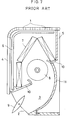
- FIG. 7 illustrates the construction of the above indoor unit which has an inlet port 1 at an upper portion, an outlet port 2 at a lower portion thereof, and an air flow passage 3 defined between the inlet port 1 and the outlet port 2.
- a removable air filter 6 inserted along the inner surface of a front cover 4 as extending to a ceiling side of a main body frame 5, a heat exchanger 7 comprised of three portions arranged in a bent relation, and a fan placed in a space enclosed by the heat exchanger 7.
- the direction of an air flow into room is adjusted by means of a vane 9 disposed at the outlet port 2.
- a drain pan 10 serves to receive condensation dropping from different portions of the heat exchanger 7, and the drain pan 10 also constitutes a portion of a wall defining the air flow passage 3.
- the air flow passage 3 extending from the fan 8 to the outlet port 2 is provided with a rear guider 11 on the rear side thereof.
- the indoor unit of the air conditioner having the aforementioned construction has the following problems. Because of narrow spaces between the fan 8 and the heat exchanger 7 at a front-side and a rear-side portion thereof, streams of sucked air bump against each other and hence, a turbulent flow tends to occur. If the rear-side portion of the heat exchanger 7 is inclined at a small angle with respect to the vertical, a smaller amount of air is sucked into the rear-side portion of the heat exchanger 7 through the inlet port 1 in the top surface. Adversely, if the aforesaid inclination is great, the rear-side portion of the heat exchanger 7 is located closer to the fan 8, resulting in a higher level of noise.
- the inlet port does not exist at a portion where the main body frame 5 joins the front cover 4 and therefore, air suction into the rear-side portion of the heat exchanger 7 is retarded to cause imbalance in the air flow.
- the resultant uneven distribution of flow velocity lowers the performance of flow rate.
- the indoor unit of the air conditioner of the invention comprises a main body frame, a front cover having an inlet port in a top and a front surface thereof while cooperating with the main body frame to form an air flow passage extending toward an outlet port disposed at the lower end thereof, a cross-flow fan having an impeller formed of a plurality of blades arranged in a column-like form, heat exchangers disposed upstream of the cross-flow fan within the air flow passage independently from each other at the front side and the rear side in the passage, a leaf for interconnecting both the heat exchangers at the upper portions thereof, a stabilizer disposed adjacent to and opposite to the cross-flow fan, and a rear guider defining the air flow passage extending from the cross-flow fan to the outlet port, the rear-side heat exchanger being inclined toward the cross-flow fan at an angle ⁇ with respect to the vertical, the angle ⁇ being in the range of 25° ⁇ ⁇ ⁇ 35°.
- Such an arrangement assures sufficient suction of air through the rear-side heat exchanger, the air entering through the inlet port in the top portion of the front cover, while preventing an increase in the noise level which results from the position of the rear-side heat exchanger being too close to the cross-flow fan. Furthermore, wider spaces between the cross-flow fan and the heat exchangers at the front and the rear sides provides space allowing for the installation of an additional function element such as a heating element or the like.
- a more preferred mode of the invention in which the front-side heat exchanger comprises two portions arranged in a bent form improves the suction performance of the front-side heat exchanger.
- additional function elements such as a heater or the like.
- a portion where the main body frame joins the front cover and no opening exists is superposed relative to the leaf presenting no suction capability, thereby reducing an area retarding air suction to increase the performance of flow rate.
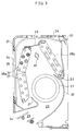
- Fig.1 is a transverse sectional view of a first embodiment of the present invention.
- an indoor unit 20 includes an air flow passage 23 defined between a main body frame 21 and a front cover 22, the air flow passage 23 communicating with a room space via an inlet port 24 and an outlet port 25.
- the inlet port 24 exists in the front and the top surfaces of the front cover 22 as well as in the top surface of the main body frame 21.
- the outlet port 25 exists at the lower end of the front cover 22.
- the cross-flow fan 27 is formed of a plurality of unitized bodies of impellers arranged along the direction of a rotary axis, the unitized body of the impeller being formed of a plurality of blades arranged in a column-like form.
- the heat exchangers 28a and 28b are disposed upstream of the cross-flow fan 27 in the air flow passage 23 independently from each other on the front and the rear sides therein. Both the heat exchangers 28a and 28b are interconnected at the upper portions thereof by means of a leaf 29.
- the heat exchanger 28b on the rear side is inclined toward the cross-flow fan 27 at an angle ⁇ with respective to the vertical.
- a suitable inclination angle ⁇ is in the range of 25° ⁇ ⁇ ⁇ 35°, and such an inclination is set at 30° in this embodiment.
- An additional function element such as a heater 30 is interposed between the heat exchangers 28a and 28b. However, it is not essential that the additional function element be provided.
- a stabilizer 31 On the downstream side of the cross-flow fan 27 in the air flow passage, there are disposed a stabilizer 31 adjacent to and opposite to the cross-flow fan 27, and a rear guider 32 defining the air flow passage 23 extending from the cross-flow fan 27 to the outlet port 25.
- a part of the rear guider 32 and the stabilizer 31 each defines a drain pan 33 for receiving condensation dropping from the heat exchangers 28a and 28b.
- a vane 34 to adjust a direction of air flow into room is rotatably provided at the outlet port 25.
- air in a room flows through the inlet port 24 in the front cover 22 and the main body frame 21 and through the air filter 26 into the air flow passage 23, and the air penetrates the heat exchangers 28a and 28b to be sucked by the cross-flow fan 27.
- the cross-flow fan 27 discharges the sucked air into space in the room from the outlet port 25 by way of the air flow passage 23 defined by the rear guider 32 and the stabilizer 31.
- Fig.2 illustrates the relationship between an inclination ⁇ of the rear-side heat exchanger 28b with respect to the vertical and air flow ratio at an identical noise level.
- a noise level increases.
- air flow ratio as compared at an identical noise level is lowered.
- an optimum value of the inclination ⁇ of the rear-side heat exchanger 28b with respect to the vertical is in the range of 25° ⁇ ⁇ ⁇ 35°.
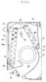
- Fig.3 is a transverse sectional view of the second embodiment of the present invention. Components having the same function as do those shown in Fig.1 are represented by the same reference numerals and therein descriptions are omitted.
- the front-side heat exchanger 28a comprises two portions U and D arranged in a bent form.
- an air flow toward a cross-flow fan 27 from the upper portion U of the bent form of the frontside heat exchanger 28a suffers less flow loss due to deflection, thereby increasing air flow ratio.
- the bent form of the front-side heat exchanger 28a can widen room surrounded by the heat exchangers 28a, 28b and the cross-flow fan 27, where additional function elements such as a heater 30 is readily installed. It is noted that although the front-side heat exchanger 28a comprises two portions arranged in the bent form, an equivalent effect may be attained by a structure in which three or more portions are arranged in a bent form.
- Fig.4 is a transverse sectional view of the third embodiment of the present invention. Components having the same function as do those shown in Fig.1 are represented by the same reference numerals and therein descriptions are omitted.
- a joint section 35 of a front cover 22 and a main body frame 21 is positioned above a leaf 29 interconnecting a front-side heat exchanger 28a and a rear-side heat exchanger 28b at the upper portions thereof.
- Fig.5 is a transverse sectional view of the fourth embodiment of the present invention. Components having the same function as those shown in Fig.1 are represented by the same reference numerals and therein descriptions are omitted.
- a ratio of the two independent heat exchangers 28a,28b by the number of heat exchanger area therein (area flow ratio) is 9:6.
- the number of heat exchanger area is counted on the basis of a piping pitch and is proportional to the area of the heat exchanger.
- "P" corresponds to one section of the heat exchanger area.
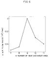
- Fig.6 illustrates the relationship between a ratio of the front-side heat exchanger 28a to the rear-side heat exchanger 28b by the number of the heat exchanger sections and air flow ratio at the same noise level, in the case where the capacity of space disposing the heat exchangers 28a, 28b is fixed and the sum of heat exchanger sections of the front-side and rear-side heat exchangers 28a and 28b is fixed (the sum of the heat exchanger sections is 15 in this embodiment).
- a ratio of the two heat exchangers 28a and 28b by the number of the heat exchanger sections is indicated by way of, for simplicity, the number of the heat exchanger sections of the front-side heat exchanger 28a.
- the number of the heat exchanger sections of the rear-side heat exchanger 28b is found by subtracting the number of the heat exchanger sections of the front-side heat exchanger 28a from 15.
- the front-side heat exchanger 28a is inclined at a greater angle ⁇ with respect to the vertical, so that is approaches a cross-flow fan 27 to increase level, resulting in poor air flow ratio. If the front-side heat exchanger 28a accounts for 12 or more in the aforesaid ratio, there is a possibility that condensation drops from the front-side heat exchanger 28a.
Landscapes
- Engineering & Computer Science (AREA)
- Chemical & Material Sciences (AREA)
- Combustion & Propulsion (AREA)
- Mechanical Engineering (AREA)
- General Engineering & Computer Science (AREA)
- Physics & Mathematics (AREA)
- Thermal Sciences (AREA)
- Air Filters, Heat-Exchange Apparatuses, And Housings Of Air-Conditioning Units (AREA)
- Air-Conditioning Room Units, And Self-Contained Units In General (AREA)
- Devices For Blowing Cold Air, Devices For Blowing Warm Air, And Means For Preventing Water Condensation In Air Conditioning Units (AREA)
Applications Claiming Priority (2)
| Application Number | Priority Date | Filing Date | Title |
|---|---|---|---|
| JP7234923A JPH0979656A (ja) | 1995-09-13 | 1995-09-13 | 空気調和機の室内ユニット |
| JP234923/95 | 1995-09-13 |
Publications (1)
| Publication Number | Publication Date |
|---|---|
| EP0763697A1 true EP0763697A1 (fr) | 1997-03-19 |
Family
ID=16978408
Family Applications (1)
| Application Number | Title | Priority Date | Filing Date |
|---|---|---|---|
| EP96114659A Withdrawn EP0763697A1 (fr) | 1995-09-13 | 1996-09-12 | Unité d'intérieur pour dispositif de conditionnement d'air |
Country Status (4)
| Country | Link |
|---|---|
| EP (1) | EP0763697A1 (fr) |
| JP (1) | JPH0979656A (fr) |
| KR (1) | KR970016352A (fr) |
| CN (1) | CN1152692A (fr) |
Cited By (3)
| Publication number | Priority date | Publication date | Assignee | Title |
|---|---|---|---|---|
| AU698164B1 (en) * | 1998-01-30 | 1998-10-22 | Mitsubishi Denki Kabushiki Kaisha | Ceiling built-in type air conditioner |
| EP1628082A3 (fr) * | 2004-08-19 | 2009-02-18 | LG Electronics Inc. | Dispositif de climatisation autoportant |
| US20240418378A1 (en) * | 2023-06-14 | 2024-12-19 | Quilt Systems, Inc. | Indoor unit mechanical structure for improved form factor |
Families Citing this family (3)
| Publication number | Priority date | Publication date | Assignee | Title |
|---|---|---|---|---|
| JP5935167B2 (ja) * | 2012-07-20 | 2016-06-15 | ジョンソンコントロールズ ヒタチ エア コンディショニング テクノロジー(ホンコン)リミテッド | 空気調和機 |
| CN106322535A (zh) * | 2016-09-20 | 2017-01-11 | Tcl空调器(中山)有限公司 | 空调器室内机以及空调器 |
| CN107192014B (zh) * | 2017-05-11 | 2019-12-06 | 青岛海尔空调器有限总公司 | 空调室内机 |
Citations (4)
| Publication number | Priority date | Publication date | Assignee | Title |
|---|---|---|---|---|
| EP0466431A1 (fr) * | 1990-07-06 | 1992-01-15 | Mitsubishi Denki Kabushiki Kaisha | Système de contrôle à conditionnement d'air |
| EP0560037A1 (fr) * | 1992-03-13 | 1993-09-15 | Kabushiki Kaisha Toshiba | Appareil de conditionnement d'air avec orifices réglable |
| JPH07190474A (ja) * | 1993-12-24 | 1995-07-28 | Matsushita Electric Ind Co Ltd | 空気調和機の室内ユニット |
| JPH07190476A (ja) * | 1993-12-24 | 1995-07-28 | Matsushita Electric Ind Co Ltd | 空気調和機の室内ユニット |
-
1995
- 1995-09-13 JP JP7234923A patent/JPH0979656A/ja active Pending
-
1996
- 1996-09-12 EP EP96114659A patent/EP0763697A1/fr not_active Withdrawn
- 1996-09-12 KR KR1019960039574A patent/KR970016352A/ko not_active Withdrawn
- 1996-09-13 CN CN96113422A patent/CN1152692A/zh active Pending
Patent Citations (4)
| Publication number | Priority date | Publication date | Assignee | Title |
|---|---|---|---|---|
| EP0466431A1 (fr) * | 1990-07-06 | 1992-01-15 | Mitsubishi Denki Kabushiki Kaisha | Système de contrôle à conditionnement d'air |
| EP0560037A1 (fr) * | 1992-03-13 | 1993-09-15 | Kabushiki Kaisha Toshiba | Appareil de conditionnement d'air avec orifices réglable |
| JPH07190474A (ja) * | 1993-12-24 | 1995-07-28 | Matsushita Electric Ind Co Ltd | 空気調和機の室内ユニット |
| JPH07190476A (ja) * | 1993-12-24 | 1995-07-28 | Matsushita Electric Ind Co Ltd | 空気調和機の室内ユニット |
Non-Patent Citations (1)
| Title |
|---|
| PATENT ABSTRACTS OF JAPAN vol. 95, no. 007 * |
Cited By (4)
| Publication number | Priority date | Publication date | Assignee | Title |
|---|---|---|---|---|
| AU698164B1 (en) * | 1998-01-30 | 1998-10-22 | Mitsubishi Denki Kabushiki Kaisha | Ceiling built-in type air conditioner |
| EP1628082A3 (fr) * | 2004-08-19 | 2009-02-18 | LG Electronics Inc. | Dispositif de climatisation autoportant |
| US20240418378A1 (en) * | 2023-06-14 | 2024-12-19 | Quilt Systems, Inc. | Indoor unit mechanical structure for improved form factor |
| US12339015B2 (en) * | 2023-06-14 | 2025-06-24 | Quilt Systems, Inc. | Indoor unit mechanical structure for improved form factor |
Also Published As
| Publication number | Publication date |
|---|---|
| CN1152692A (zh) | 1997-06-25 |
| JPH0979656A (ja) | 1997-03-28 |
| KR970016352A (ko) | 1997-04-28 |
Similar Documents
| Publication | Publication Date | Title |
|---|---|---|
| EP1326054A1 (fr) | Panneau decoratif pour systemes de climatisation, unite de sortie d'air, et systeme de climatisation | |
| US6196303B1 (en) | Fancoil assemblies | |
| CN215597479U (zh) | 天花机及空调器 | |
| KR19980050605A (ko) | 공기 조화기의 상방흡입 횡류형 실내기 | |
| EP1989487B1 (fr) | Unite d'exterieur pour climatiseurs | |
| EP0763697A1 (fr) | Unité d'intérieur pour dispositif de conditionnement d'air | |
| AU2003284611B2 (en) | Indoor unit for air conditioner | |
| EP1316760B1 (fr) | Panneau de decoration pour systeme de climatisation, unite d'echappement d'air de sortie, et systeme de climatisation | |
| JP3387712B2 (ja) | 天井埋込型空気調和機の室内ユニット | |
| JPH07217987A (ja) | 空気調和機用熱交換器 | |
| EP1813877A2 (fr) | Unité intérieure d'un climatiseur | |
| JPH0590213U (ja) | 空気調和機の室内ユニット | |
| CN116241941B (zh) | 空调器 | |
| JP3141663B2 (ja) | 空気調和機の室内ユニット | |
| JP3171487B2 (ja) | 空気調和機 | |
| CN224018470U (zh) | 空调器 | |
| JP2706383B2 (ja) | 天井埋込形空気調和機 | |
| CN216644348U (zh) | 壁挂式空调器 | |
| CN222504068U (zh) | 风管机 | |
| CN213040657U (zh) | 室内空气处理一体机 | |
| CN222578371U (zh) | 风管机 | |
| CN219264435U (zh) | 一种空调器 | |
| CN222560142U (zh) | 空调器 | |
| JP3610585B2 (ja) | 空気調和機の室内ユニット | |
| CN213841125U (zh) | 空调室内机 |
Legal Events
| Date | Code | Title | Description |
|---|---|---|---|
| PUAI | Public reference made under article 153(3) epc to a published international application that has entered the european phase |
Free format text: ORIGINAL CODE: 0009012 |
|
| AK | Designated contracting states |
Kind code of ref document: A1 Designated state(s): ES GR IT |
|
| 17P | Request for examination filed |
Effective date: 19970509 |
|
| 17Q | First examination report despatched |
Effective date: 19990628 |
|
| STAA | Information on the status of an ep patent application or granted ep patent |
Free format text: STATUS: THE APPLICATION IS DEEMED TO BE WITHDRAWN |
|
| 18D | Application deemed to be withdrawn |
Effective date: 19991109 |