EP0763699A2 - Heilklimagerät - Google Patents
Heilklimagerät Download PDFInfo
- Publication number
- EP0763699A2 EP0763699A2 EP96116225A EP96116225A EP0763699A2 EP 0763699 A2 EP0763699 A2 EP 0763699A2 EP 96116225 A EP96116225 A EP 96116225A EP 96116225 A EP96116225 A EP 96116225A EP 0763699 A2 EP0763699 A2 EP 0763699A2
- Authority
- EP
- European Patent Office
- Prior art keywords
- air
- intermediate housing
- housing
- healing
- housing part
- Prior art date
- Legal status (The legal status is an assumption and is not a legal conclusion. Google has not performed a legal analysis and makes no representation as to the accuracy of the status listed.)
- Granted
Links
Images
Classifications
-
- A—HUMAN NECESSITIES
- A61—MEDICAL OR VETERINARY SCIENCE; HYGIENE
- A61L—METHODS OR APPARATUS FOR STERILISING MATERIALS OR OBJECTS IN GENERAL; DISINFECTION, STERILISATION OR DEODORISATION OF AIR; CHEMICAL ASPECTS OF BANDAGES, DRESSINGS, ABSORBENT PADS OR SURGICAL ARTICLES; MATERIALS FOR BANDAGES, DRESSINGS, ABSORBENT PADS OR SURGICAL ARTICLES
- A61L9/00—Disinfection, sterilisation or deodorisation of air
- A61L9/16—Disinfection, sterilisation or deodorisation of air using physical phenomena
- A61L9/18—Radiation
- A61L9/20—Ultraviolet radiation
-
- F—MECHANICAL ENGINEERING; LIGHTING; HEATING; WEAPONS; BLASTING
- F24—HEATING; RANGES; VENTILATING
- F24F—AIR-CONDITIONING; AIR-HUMIDIFICATION; VENTILATION; USE OF AIR CURRENTS FOR SCREENING
- F24F1/00—Room units for air-conditioning, e.g. separate or self-contained units or units receiving primary air from a central station
- F24F1/02—Self-contained room units for air-conditioning, i.e. with all apparatus for treatment installed in a common casing
- F24F1/0328—Self-contained room units for air-conditioning, i.e. with all apparatus for treatment installed in a common casing with means for purifying supplied air
- F24F1/035—Self-contained room units for air-conditioning, i.e. with all apparatus for treatment installed in a common casing with means for purifying supplied air characterised by the mounting or arrangement of filters
-
- A—HUMAN NECESSITIES
- A61—MEDICAL OR VETERINARY SCIENCE; HYGIENE
- A61H—PHYSICAL THERAPY APPARATUS, e.g. DEVICES FOR LOCATING OR STIMULATING REFLEX POINTS IN THE BODY; ARTIFICIAL RESPIRATION; MASSAGE; BATHING DEVICES FOR SPECIAL THERAPEUTIC OR HYGIENIC PURPOSES OR SPECIFIC PARTS OF THE BODY
- A61H33/00—Bathing devices for special therapeutic or hygienic purposes
- A61H33/06—Artificial hot-air or cold-air baths; Steam or gas baths or douches, e.g. sauna or Finnish baths
- A61H33/08—Air douches for hygienic purposes
-
- F—MECHANICAL ENGINEERING; LIGHTING; HEATING; WEAPONS; BLASTING
- F24—HEATING; RANGES; VENTILATING
- F24F—AIR-CONDITIONING; AIR-HUMIDIFICATION; VENTILATION; USE OF AIR CURRENTS FOR SCREENING
- F24F1/00—Room units for air-conditioning, e.g. separate or self-contained units or units receiving primary air from a central station
- F24F1/0007—Indoor units, e.g. fan coil units
- F24F1/0071—Indoor units, e.g. fan coil units with means for purifying supplied air
-
- F—MECHANICAL ENGINEERING; LIGHTING; HEATING; WEAPONS; BLASTING
- F24—HEATING; RANGES; VENTILATING
- F24F—AIR-CONDITIONING; AIR-HUMIDIFICATION; VENTILATION; USE OF AIR CURRENTS FOR SCREENING
- F24F3/00—Air-conditioning systems in which conditioned primary air is supplied from one or more central stations to distributing units in the rooms or spaces where it may receive secondary treatment; Apparatus specially designed for such systems
- F24F3/12—Air-conditioning systems in which conditioned primary air is supplied from one or more central stations to distributing units in the rooms or spaces where it may receive secondary treatment; Apparatus specially designed for such systems characterised by the treatment of the air otherwise than by heating and cooling
-
- F—MECHANICAL ENGINEERING; LIGHTING; HEATING; WEAPONS; BLASTING
- F24—HEATING; RANGES; VENTILATING
- F24F—AIR-CONDITIONING; AIR-HUMIDIFICATION; VENTILATION; USE OF AIR CURRENTS FOR SCREENING
- F24F8/00—Treatment, e.g. purification, of air supplied to human living or working spaces otherwise than by heating, cooling, humidifying or drying
- F24F8/10—Treatment, e.g. purification, of air supplied to human living or working spaces otherwise than by heating, cooling, humidifying or drying by separation, e.g. by filtering
-
- F—MECHANICAL ENGINEERING; LIGHTING; HEATING; WEAPONS; BLASTING
- F24—HEATING; RANGES; VENTILATING
- F24F—AIR-CONDITIONING; AIR-HUMIDIFICATION; VENTILATION; USE OF AIR CURRENTS FOR SCREENING
- F24F8/00—Treatment, e.g. purification, of air supplied to human living or working spaces otherwise than by heating, cooling, humidifying or drying
- F24F8/20—Treatment, e.g. purification, of air supplied to human living or working spaces otherwise than by heating, cooling, humidifying or drying by sterilisation
- F24F8/22—Treatment, e.g. purification, of air supplied to human living or working spaces otherwise than by heating, cooling, humidifying or drying by sterilisation using UV light
-
- F—MECHANICAL ENGINEERING; LIGHTING; HEATING; WEAPONS; BLASTING
- F24—HEATING; RANGES; VENTILATING
- F24F—AIR-CONDITIONING; AIR-HUMIDIFICATION; VENTILATION; USE OF AIR CURRENTS FOR SCREENING
- F24F1/00—Room units for air-conditioning, e.g. separate or self-contained units or units receiving primary air from a central station
- F24F1/06—Separate outdoor units, e.g. outdoor unit to be linked to a separate room comprising a compressor and a heat exchanger
- F24F1/08—Compressors specially adapted for separate outdoor units
-
- F—MECHANICAL ENGINEERING; LIGHTING; HEATING; WEAPONS; BLASTING
- F24—HEATING; RANGES; VENTILATING
- F24F—AIR-CONDITIONING; AIR-HUMIDIFICATION; VENTILATION; USE OF AIR CURRENTS FOR SCREENING
- F24F6/00—Air-humidification, e.g. cooling by humidification
Definitions
- the invention relates to a healing air conditioner with a housing having a housing upper part and a housing lower part, which has an air guiding duct which receives a blower and is connected to the surroundings via an air inlet and an air outlet opening.
- Such a healing air conditioner is known from DE 35 18 456 C2.
- ambient air is drawn in by a blower through the air inlet opening into the air duct.
- the air is led past various lights before it reaches the blower.
- the luminaires emit various spectra of UV light, which are used to kill microorganisms in the air.
- the air blows past an electronic heater behind the fan.
- it is passed through a water mist.
- the water for the water mist is in one Shell attached to the lower part of the housing.
- the air passed through the water mist is enriched with moisture and salts or essential oils and released into the environment again through the air outlet opening.
- the healing air conditioning unit is controlled via a central power unit.
- the individual electrical units are encapsulated.
- individual housings are used in which the electronic components are embedded in a moisture-tight manner.
- an intermediate housing part is formed in the housing, which has an intermediate housing upper part and an intermediate housing lower part and encloses a receiving space for electronic components in a moisture-tight manner.
- the intermediate housing part can be preassembled as a separate assembly outside the healing air conditioner.
- the electronic components are installed in the intermediate housing part.
- the intermediate housing part can be separated into an intermediate housing upper part and a lower part.
- the receiving space for the electronic components is then easily accessible.
- the intermediate housing part can be assembled and sealed.
- the air duct is formed between the upper housing part and the lower housing part. This eliminates the need for separate components for the air flow.
- the blower has a compressor wheel arranged on a holding section of the intermediate housing upper part, and that the compressor wheel is arranged in the air guide duct under an air filter box.
- the air inlet opening of the air duct is covered upwards, so that the air is sucked into the air duct against the direction of gravity, then it is prevented in a simple manner that contamination of the air duct as a result of dust particles sinking into the environment when the air conditioning unit is not in operation occur.
- the air duct is divided into two areas by means of a partition, that the partition has a recess which connects the two regions, that the first region lying in front of the partition in the air flow direction comprises the compressor wheel and the one in Direction of air flow behind the partition lying second area receives the UV lamp and a spray device designed as a shower pipe and that the second area has air outlet openings and is spatially connected to a lower part of the housing receiving a water supply.
- the lower intermediate housing part has downwardly projecting feet and that the intermediate housing part is set in the lower housing part.
- a possible variant of the invention is characterized in that the electrical components are mounted on a base plate, and that the base plate is connected to the holding section of the intermediate housing upper part.
- the electronic components can be mounted on the base plate.
- the base plate can then be installed in the intermediate housing.
- FIG. 1 shows a healing air conditioner with a lower housing part 90 and an upper housing part 10.
- the upper housing part 10 has a cover 10.1, which is provided with air outlet openings 12.
- an operating unit 14 is arranged next to the cover 10.1.
- 90 recessed grips 97 are formed laterally in the lower housing part. The cover 10.1 can be lifted off the upper housing part 10 after a lock 13 has been released.
- FIG. 2 shows the healing air conditioner with the cover 10.1 removed.
- the cover covers a filter element 33, a partition 50 with molded cover 53 and a shower pipe 61.
- a UV lamp 60 which cannot be seen in this illustration, is arranged under the cover 53.
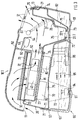
- FIG. 3 shows in side view and in section the healing air conditioner.
- An intermediate housing is arranged between the upper housing part 10 and the lower housing part 90 and is essentially formed from an intermediate housing upper part 20 and an intermediate housing lower part 70.
- the intermediate housing upper part 20 is provided with a circumferential bent edge 21. With this cranked edge 21, the intermediate housing upper part 20 is placed on an upwardly angled edge 71 of the intermediate housing lower part 70.
- the connection of the intermediate housing upper part 20 to the intermediate housing lower part 70 takes place by means of screw connections.
- fastening screws are screwed into the cranked edge 21 and the angled edge 71.
- a sealing ring can be inserted between the bent edge 21 and the angled edge 71.
- An intermediate space 75 is formed between the intermediate housing upper part 20 and the intermediate housing lower part 70, in which electrical components 80 are accommodated.
- the electrical components 80 are mounted on a base plate 80.
- the base plate 81 is in turn connected to a holding section 23 of the intermediate housing upper part 20.
- Downwardly projecting feet 72 are integrally formed on the lower intermediate housing part 70.
- the intermediate housing formed from the intermediate housing upper part 20 and the intermediate housing lower part 70 is inserted into the housing lower part 90.
- the feet 72 are supported on the bottom of the lower housing part 90.
- the intermediate housing is supported on the front with its intermediate housing lower part 70 on a side wall 92 of the lower housing part 90.
- the intermediate housing is supported on the front with its intermediate housing lower part 70 on a side wall 92 of the lower housing part 90.
- On the rear side the side wall 92 has a cranked edge 93 on which the intermediate housing 70 is supported. The intermediate housing is thus held centered in the lower housing part 90.
- the lower housing part 90 serves to hold a water supply.
- a pump 96 with its suction pipe protrudes into the area of the lower housing part 90 receiving the water supply.
- the pump 96 is fixed to the intermediate housing lower part 70.
- a level sensor 94 which is mounted on one of the feet 72, is used to detect the water level.
- An air duct is formed between the cover 10.1 of the upper housing part 10 and the upper intermediate housing part 20.
- the air duct is connected to the environment via an air inlet opening 11 and air outlet opening 12.
- the air inlet opening 11 is formed between the cover 10.1 and the intermediate housing upper part 20.
- the cover 10.1 protrudes from the rear over the intermediate housing upper part 20.
- the air inlet opening 11 is open at the bottom, so that no dust can enter the air duct when the healing air conditioner is not in operation.
- the air duct is divided into two areas by means of the partition wall 60.
- a fan having a compressor wheel 40 is introduced.
- the blower is fixed on the holding section 23.
- the intermediate housing upper part 20 has an air filter box receptacle 22.
- An air filter box 30 is placed on this air box holder 22.
- a grate 32 is fastened in the air filter box 30.
- the grate 32 carries a filter element 33.
- the UV lamp 60 and a spray device designed as a shower pipe 61 are arranged in the second area assigned to the air outlet openings 12.
- the partition 50 carries a cover 53 which covers the UV lamp 60.
- the leg 54 of the cover 53 prevents light, which is emitted by the UV lamp 60, from reaching the surroundings through the air outlet openings 12 of the cover 10.1.
- the partition 50 has an opening 52, by means of which the first and the second region of the air duct are connected.
- the partition 50 is inserted with a plug 51 in a slot 24 of the intermediate housing upper part 20.
- the fan With its compressor wheel 40, the fan sucks in ambient air through the air inlet opening 11.
- the sucked-in air enters the compressor wheel 40 through the filter element 33 and the grate 32 in the axial direction of the axis of rotation.
- the air flow is deflected by 90 ° and emitted again radially outward over the circumference of the compressor wheel 40.
- the dividing wall 50, the air filter box 30, the holding section 23 and the upwardly directed web of the intermediate housing upper part 20 adjoining the holding section 23 form a housing within which the compressor wheel 40 is arranged.
- the air blown out by the compressor wheel 40 is thus conducted through the opening 52 of the partition 50 into the second region of the air duct. After passing through the opening 52, the air is irradiated with the UV lamp 60. This kills germs that are carried in the air. The air is then passed through a water curtain produced by the shower pipe 61. Here, the air absorbs moisture and then flows back into the environment through the air outlet opening 12.
- the water is supplied to the shower pipe 61 by the pump 96 via a channel system.
- the remaining water not absorbed by the air is intercepted by a baffle 27 of the intermediate housing upper part 20 and discharged downwards via a slope 26. From here it reaches a recess 25 which is formed by the intermediate housing upper part 20.
- the recess 25 is connected via an opening 20.1 to the water supply accommodated in the lower housing part 90.
- the water that is not carried by the air flow can thus return to the water supply of the lower housing part 90 and is again available to the pump 96.
- An annular extension 20.2 is connected to the opening 20.1 and is inserted into a recess 73 of the intermediate housing lower part 70.
- the annular extension 20.2 is sealed against the intermediate housing lower part 70 by means of an annular seal.
- the shower pipe 61 guides the sprayed water at an acute angle against the baffle 27.
- the cover 10.1 must be removed. This is possible because the lock 13 formed on the front is released.
- a handle is provided, by means of which the lid can be pulled up, the locking 13 resiliently springs back on the edge 29 of the intermediate housing upper part 20.
- the filter element 33 is accessible. To replace it, it can simply be removed from the air filter box 30 from the grate 32 and exchanged for a new filter element 33.
- the partition 50 can be pulled up out of the housing. As a result, the UV lamp 60 is exposed and can be cleaned with a cloth or simply replaced in the event of damage.
- the shower pipe 61 is removably inserted from above into receptacles. It can be easily pulled out and cleaned from the outside and inside with a brush. In order to ensure that after the reinstallation of the shower pipe 61, the spray angle against the baffle wall 27 is maintained, guides are provided on the receptacles holding the shower pipe 61, which allow only a single installation position.
- the unit consisting of the upper housing part 10, the intermediate housing upper part 20 and the intermediate housing lower part 70 can be lifted off the lower housing part 90.
- the lower housing part 90 can then be cleaned or water filled up.
- a water level indicator 95 on the lower housing part 90 shows the current fill level.
- the UV lamp 60 radiates into the recess 25 of the intermediate housing upper part 25. It also irradiates the water supply accommodated in the lower housing part 90. As a result, the water is disinfected.
- a time-limited sterilization process also begins after the device is switched on, the UV lamp 60 sterilizing the water supply. In this operating state, the fan is not yet in operation. The device starts after the disinfection process.
- a Schumann wave generator (not shown in the drawings). This generates an oscillation frequency that is transferred to the water drops.
- the frequency of a Schumann wave also corresponds to a vibration of 7.8 Hz, which is also increasingly measurable near the sea.
Landscapes
- Engineering & Computer Science (AREA)
- Combustion & Propulsion (AREA)
- Mechanical Engineering (AREA)
- General Engineering & Computer Science (AREA)
- Chemical & Material Sciences (AREA)
- Health & Medical Sciences (AREA)
- Public Health (AREA)
- Animal Behavior & Ethology (AREA)
- Epidemiology (AREA)
- Veterinary Medicine (AREA)
- General Health & Medical Sciences (AREA)
- Life Sciences & Earth Sciences (AREA)
- Rehabilitation Therapy (AREA)
- Physical Education & Sports Medicine (AREA)
- Pain & Pain Management (AREA)
- Disinfection, Sterilisation Or Deodorisation Of Air (AREA)
- Compression-Type Refrigeration Machines With Reversible Cycles (AREA)
- Central Air Conditioning (AREA)
- Physical Water Treatments (AREA)
- Air Filters, Heat-Exchange Apparatuses, And Housings Of Air-Conditioning Units (AREA)
- Filtering Of Dispersed Particles In Gases (AREA)
- Cooling Or The Like Of Electrical Apparatus (AREA)
- Medicines Containing Material From Animals Or Micro-Organisms (AREA)
Abstract
Description
- Die Erfindung betrifft ein Heilklimagerät mit einem ein Gehäuseoberteil und ein Gehäuseunterteil aufweisendem Gehäuse, das einen ein Gebläse aufnehmenden Luftführungskanal aufweist, der über eine Lufteintritts- und eine Luftaustrittsöffnung mit der Umgebung in Verbindung steht.
- Ein derartiges Heilklimagerät ist aus der DE 35 18 456 C2 bekannt. Bei diesem bekannten Heilklimagerät wird von einem Gebläse Umgebungsluft durch die Lufteintrittsöffnung in den Luftführungskanal eingesaugt. Die Luft wird noch bevor sie das Gebläse erreicht, an verschiedenen Leuchten vorbeigeführt. Die Leuchten senden verschiedene Spektren von UV-Licht aus, mit dem Mikroorganismen in der Luft abgetötet werden. Hinter dem Gebläse streicht die Luft an einer elektronischen Heizeinrichtung vorbei. Dann wird sie durch einen Wassernebel geleitet. Das Wasser für den Wassernebel ist in einer, am Gehäuseunterteil festgemachten Schale bevorratet. Die durch den Wassernebel hindurchgeführte Luft wird mit Feuchtigkeit und Salzen bzw. ätherischen Ölen angereichert und wieder in die Umgebung durch die Luftaustrittsöffnung abgegeben. Die Steuerung des Heilklimagerätes erfolgt über ein zentrales Leistungsteil.
- Da in dem Heilklimagerät Wasser und Elektrizität geleitet wird, ist hohen Sicherheitsanforderungen zu entsprechen. Aus diesem Grund werden die einzelnen elektrischen Einheiten gekapselt. Dazu werden jeweils einzelne Gehäuse verwendet, in die die elektronischen Bauelemente feuchtigkeitsdicht eingebettet sind.
- Für die Trennung der stromführenden Teile von dem im Heilklimagerät geleiteten Wasser ist ein hoher Teile- und Montageaufwand notwendig. Auch sind hohe Anforderungen an den Monteur eines solchen Heilklimagerätes zu stellen, denn er muß sorgfältig die einzelnen elektronischen Bauelemente wassergeschützt einbauen. Anschließend muß er, ebenfalls wassergeschützt, die Verdrahtung vornehmen.
- Es ist die Aufgabe der Erfindung, ein Heilklimagerät der eingangs erwähnten Art zu schaffen, das bei geringem Teileaufwand eine einfache Montage ermöglicht.
- Diese Aufgabe wird dadurch gelöst, daß in dem Gehäuse ein Zwischengehäuseteil gebildet ist, das ein Zwischengehäuseoberteil und ein Zwischengehäuseunterteil aufweist und einen Aufnahmeraum für elektronische Bauelemente feuchtigkeitsdicht umschließt.
- Das Zwischengehäuseteil kann als separate Baugruppe außerhalb des Heilklimagerätes vormontiert werden. In dem Zwischengehäuseteil werden die elektronischen Bauelemente eingebaut. Hierzu läßt sich das Zwischengehäuseteil in ein Zwischengehäuseoberteil und in ein -unterteil trennen. Der Aufnahmeraum für die elektronischen Bauelemente ist dann leicht zugänglich. Wenn die Bauelemente eingebaut und verdrahtet sind, dann kann das Zwischengehäuseteil zusammengebaut und abgedichtet werden.
- Nach einer Ausgestaltung der Erfindung ist vorgesehen, daß der Luftführungskanal zwischen dem Gehäuseoberteil und dem Gehäuseunterteil gebildet ist. Damit kann auf separate Bauteile für die Luftführung verzichtet werden.
- Zur Anbringung des Gebläses kann vorgesehen sein, daß das Gebläse ein auf einem Halteabschnitt des Zwischengehäuseoberteils angeordnetes Verdichterrad aufweist, und daß das Verdichterrad in dem Luftführungskanal unter einem Luftfilterkasten angeordnet ist.
- Ist vorgesehen, daß die Lufteintrittsöffnung des Luftführungskanals nach oben abgedeckt ist, so daß die Luft entgegen der Schwerkraftrichtung in den Luftführungskanal eingesaugt wird, dann ist auf einfache Weise verhindert, daß bei Nichtbetrieb des Heilklimagerätes Verschmutzungen in dem Luftführungskanal in Folge von in der Umgebung absinkenden Staubteilen auftreten.
- Nach einer bevorzugten Ausgestaltung der Erfindung ist vorgesehen, daß der Luftführungskanal mittels einer Trennwand in zwei Bereiche unterteilt ist, daß die Trennwand eine Ausnehmung aufweist, die die beiden Bereiche miteinander verbindet, daß der in Luftströmungsrichtung vor der Trennwand liegende erste Bereich das Verdichterrad und der in Luftströmungsrichtung hinter der Trennwand liegende zweite Bereich die UV-Lampe und eine als Brauserohr ausgebildete Sprühvorrichtung aufnimmt und daß der zweite Bereich Luftaustrittsöffnungen aufweist und mit einem einen Wasservorrat aufnehmenden Gehäuseunterteil in räumlicher Verbindung steht.
- Um das Zwischengehäuse abzustützen, kann vorgesehen sein, daß das Zwischengehäuseunterteil nach unten abstehende Standfüße aufweist, und daß das Zwischengehäuseteil in das Gehäuseunterteil eingestellt ist.
- Eine mögliche Erfindungsvariante ist dadurch gekennzeichnet, daß die elektrischen Bauelemente auf einer Grundplatte montiert sind, und daß die Grundplatte mit dem Halteabschnitt des Zwischengehäuseoberteils verbunden ist. Auf der Grundplatte können die elektronischen Bauelemente montiert werden. Die Grundplatte läßt sich dann in das Zwischengehäuse einbauen.
- Die Erfindung wird im folgenden anhand eines in den Zeichnungen dargestellten Ausführungsbeispiels näher erläutert. Es zeigen:
- Fig. 1
- in perspektivischer Ansicht ein Heilklimagerät mit einem Gehäuseoberteil und einem Gehäuseunterteil,
- Fig. 2
- das Heilklimagerät nach Fig. 1 mit von dem Gehäuseoberteil abgenommenem Deckel und
- Fig. 3
- das Heilklimagerät nach den Fig. 1 und 2 in Seitendarstellung und im Schnitt.
- Die Fig. 1 zeigt ein Heilklimagerät mit einem Gehäuseunterteil 90 und einem Gehäuseoberteil 10. Das Gehäuseoberteil 10 weist einen Deckel 10.1 auf, der mit Luftaustrittsöffnungen 12 versehen ist. Zum Bedienen des Heilklimagerätes ist neben dem Deckel 10.1 eine Bedieneinheit 14 angeordnet. Zum Transport des Heilklimagerätes sind seitlich in das Gehäuseunterteil 90 Griffmulden 97 eingeformt. Der Deckel 10.1 läßt sich nach Aufheben einer Verriegelung 13 von dem Gehäuseoberteil 10 abheben.
- Die Fig. 2 zeigt das Heilklimagerät mit abgehobenem Deckel 10.1. Wie aus dieser Darstellung ersichtlich ist, deckt der Deckel ein Filterelement 33, eine Trennwand 50 mit angeformter Abdeckung 53 sowie ein Brauserohr 61 ab. Unter der Abdeckung 53 ist eine in dieser Darstellung nicht ersichtliche UV-Lampe 60 angeordnet.
- Die Fig. 3 zeigt in Seitendarstellung und im Schnitt das Heilklimagerät. Zwischen dem Gehäuseoberteil 10 und dem Gehäuseunterteil 90 ist ein Zwischengehäuse angeordnet, das im wesentlichen aus einem Zwischengehäuseoberteil 20 und einem Zwischengehäuseunterteil 70 gebildet ist. Das Zwischengehäuseoberteil 20 ist mit einem umlaufenden abgekröpften Rand 21 versehen. Mit diesem abgekröpften Rand 21 ist das Zwischengehäuseoberteil 20 auf einen nach oben abgewinkelten Rand 71 des Zwischengehäuseunterteils 70 aufgesetzt. Die Verbindung des Zwischengehäuseoberteils 20 mit dem Zwischengehäuseunterteil 70 erfolgt mittels Schraubverbindungen. Hierzu sind Befestigungsschrauben in den abgekröpften Rand 21 und den abgewinkelten Rand 71 eingeschraubt. Zwischen dem abgekröpften Rand 21 und dem abgewinkelten Rand 71 kann ein Dichtring eingelegt sein. Zwischen dem Zwischengehäuseoberteil 20 und dem Zwischengehäuseunterteil 70 ist ein Zwischenraum 75 gebildet, in dem elektrische Bauelemente 80 untergebracht sind.
- Die elektrischen Bauelemente 80 sind auf einer Grundplatte 80 montiert. Die Grundplatte 81 wiederum ist mit einem Halteabschnitt 23 des Zwischengehäuseoberteils 20 verbunden. An das Zwischengehäuseunterteil 70 sind nach unten abstehende Standfüße 72 einstückig angeformt. Das aus dem Zwischengehäuseoberteil 20 und dem Zwischengehäuseunterteil 70 gebildete Zwischengehäuse ist in das Gehäuseunterteil 90 eingestellt. Hierbei stützen sich die Standfüße 72 auf dem Boden des Gehäuseunterteils 90 ab. Das Zwischengehäuse stützt sich zur Vorderseite mit seinem Zwischengehäuseunterteil 70 an einer Seitenwand 92 des Gehäuseunterteils 90 ab. Das Zwischengehäuse stützt sich zur Vorderseite mit seinem Zwischengehäuseunterteil 70 an einer Seitenwand 92 des Gehäuseunterteils 90 ab. Rückseitig weist die Seitenwand 92 einen abgekröpften Rand 93 auf, an dem sich das Zwischengehäuse 70 anstützt. Damit ist das Zwischengehäuse zentriert in dem Gehäuseunterteil 90 gehalten.
- Das Gehäuseunterteil 90 dient zur Aufnahme eines Wasservorrates. In den den Wasservorrat aufnehmenden Bereich des Gehäuseunterteils 90 ragt eine Pumpe 96 mit ihrem Ansaugrohr. Die Pumpe 96 ist an dem Zwischengehäuseunterteil 70 festgelegt. Zur Detektierung des Wasserstandes ist ein Niveaugeber 94 verwendet, der an einem der Standfüße 72 montiert ist. Zwischen dem Deckel 10.1 des Gehäuseoberteils 10 und dem Zwischengehäuseoberteil 20 ist ein Luftführungskanal gebildet. Der Luftführungskanal steht über eine Lufteintrittsöffnung 11 und Luftaustrittsöffnung 12 mit der Umgebung in Verbindung. Die Lufteintrittsöffnung 11 ist zwischen dem Deckel 10.1 und dem Zwischengehäuseoberteil 20 gebildet. Hierzu steht der Deckel 10.1 rückseitig über das Zwischengehäuseoberteil 20 vor.
- Die Lufteintrittsöffnung 11 ist nach unten geöffnet, so daß bei Nichtbetrieb des Heilklimagerätes kein Staub in den Luftführungskanal eindringen kann. Der Luftführungskanal ist mittels der Trennwand 60 in zwei Bereiche unterteilt. In dem ersten Bereich, der der Lufteintrittsöffnung 11 zugeordnet ist, ist ein ein Verdichterrad 40 aufweisendes Gebläse eingebracht. Das Gebläse ist auf dem Halteabschitt 23 befestigt. Oberhalb des Verdichterrades 40 weist das Zwischengehäuseoberteil 20 eine Luftfilterkastenaufnahme 22 auf. Auf diese Luftfilderkastenaufnahme 22 ist ein Luftfilterkasten 30 aufgesetzt. In dem Luftfilterkasten 30 ist ein Rost 32 befestigt. Der Rost 32 trägt ein Filterelement 33. In dem zweiten, den Luftaustrittsöffnungen 12 zugeordneten Bereich ist die UV-Lampe 60 und eine als Brauserohr 61 ausgebildete Sprühvorrichtung angeordnet. Die Trennwand 50 trägt eine Abdeckung 53, die die UV-Lampe 60 überdeckt. Hierbei verhindert der Schenke 54 der Abdeckung 53, daß Licht, das von der UV-Lampe 60 ausgesandt wird, durch die Luftaustrittsöffnungen 12 des Deckels 10.1 in die Umgebung gelangt.
- Unterhalb der Abdeckung 53 und der UV-Lampe 60 weist die Trennwand 50 einen Durchbruch 52 auf, mittels dem der erste und der zweite Bereich des Luftführungskanals in Verbindung stehen. Die Trennwand 50 ist mit einem Steckansatz 51 in einem Schlitz 24 des Zwischengehäuseoberteils 20 eingesetzt.
- Das Gebläse saugt mit seinem Verdichterrad 40 Umgebungsluft durch die Lufteintrittsöffnung 11 an. Die angesaugte Luft tritt durch das Filterelement 33 und den Rost 32 in Achsrichtung der Drehachse in das Verdichterrad 40 ein. Im Verdichterrad 40 wird der Luftstrom um 90° umgelenkt und radial nach außen über den Umfang des Verdichterrades 40 wieder abgegeben. Die Trennwand 50, der Luftfilterkasten 30, der Halteabschnitt 23 und der an den Halteabschnitt 23 anschließende, nach oben gerichtete Steg des Zwischengehäuseoberteils 20 bilden ein Gehäuse, innerhalb dessen das Verdichterrad 40 angeordnet ist.
- Damit wird die von dem Verdichterrad 40 ausgeblasene Luft durch den Durchbruch 52 der Trennwand 50 in den zweiten Bereich des Luftführungskanals geleitet. Nach dem Durchtritt durch den Durchbruch 52 wird die Luft mit der UV-Lampe 60 bestrahlt. Hierbei werden Keime, die mit der Luft mitgeführt werden, abgetötet. Anschließend wird die Luft durch einen von dem Brauserohr 61 erzeugten Wasservorhang hindurchgeleitet. Hierbei nimmt die Luft Feuchtigkeit auf und strömt anschließend durch die Luftaustrittsöffnung 12 wieder in die Umgebung ab.
- Dem Brauserohr 61 wird das Wasser über ein Kanalsystem von der Pumpe 96 zugeführt. Das nicht von der Luft aufgenommene übrige Wasser wird von einer Prallwand 27 des Zwischengehäuseoberteils 20 abgefangen und über eine Schräge 26 nach unten abgeleitet. Von hier gelangt es in eine Vertiefung 25, die von dem Zwischengehäuseoberteil 20 gebildet ist. Die Vertiefung 25 steht über einen Durchbruch 20.1 mit dem im Gehäuseuntereil 90 aufgenommenen Wasservorrat in Verbindung. Das nicht von dem Luftstrom mitgeführte Wasser kann somit wieder in den Wasservorrat des Gehäuseunterteils 90 und steht erneut der Pumpe 96 zur Verfügung. An dem Durchbruch 20.1 ist ein ringförmiger Ansatz 20.2 angeschlossen, der in eine Ausnehmung 73 des Zwischengehäuseunterteils 70 eingesteckt ist. Der ringförmige Ansatz 20.2 ist gegen das Zwischengehäuseunterteil 70 mittels einer Ringdichtung abgedichtet. Zur Verringerung der Schallemission leitet das Brauserohr 61 das abgesprühte Wasser im spitzen Winkel gegen die Prallwand 27.
- Die Reinigung des Gerätes ist einfach möglich. Hierzu muß der Deckel 10.1 abgenommen werden. Dies ist dadurch möglich, daß die an der Vorderseite gebildete Verriegelung 13 aufgehoben wird. Hierzu ist ein Griff vorgesehen, mittels dem der Deckel nach oben gezogen werden kann, wobei die Verriegelung 13 elastisch an der Kante 29 des Zwischengehäuseoberteils 20 zurückfedert. Bei abgenommenem Deckel 10.1 ist das Filterelement 33 zugänglich. Zum Auswechseln kann es einfach aus dem Luftfilterkasten 30 vom Rost 32 abgenommen und gegen ein neues Filterelement 33 ausgetauscht werden. Zur Reinigung des zweiten Bereiches des Luftführungskanals kann die Trennwand 50 nach oben aus dem Gehäuse herausgezogen werden. Hierdurch wird die UV-Lampe 60 freigelegt und kann mit einem Tuch gereinigt oder im Schadensfall einfach ausgetauscht werden. Das Brauserohr 61 ist herausnehmbar von oben in Aufnahmen eingesetzt. Es läßt sich einfach herausziehen und von außen und innen mit einer Bürste reinigen. Um sicherzustellen, daß nach dem erneuten Einbau des Brauserohres 61 der Sprühwinkel gegen die Prallwand 27 erhalten bleibt, sind an den das Brauserohr 61 haltenden Aufnahmen Führungen vorgesehen, die nur eine einzige Einbaulage zulassen.
- Zum Nachfüllen des Wasservorrates bzw. zum Reinigen des Gehäuseunterteils 90 kann die aus dem Gehäuseoberteil 10, Zwischengehäuseoberteil 20 und Zwischengehäuseunterteil 70 bestehende Einheit von dem Gehäuseunterteil 90 abgehoben werden. Dann kann das Gehäuseunterteil 90 gereinigt oder Wasser aufgefüllt werden. Eine Wasserstandsanzeige 95 am Gehäuseunterteil 90 zeigt den aktuellen Füllstand.
- Die UV-Lampe 60 strahlt in die Vertiefung 25 des Zwischengehäuseoberteils 25 ein. Damit bestrahlt sie auch den in dem Gehäuseunterteil 90 aufgenommenen Wasservorrat. Hierdurch wird eine Entkeimung des Wassers erzielt. Vorteilhafterweise beginnt nach dem Einschalten des Gerätes auch ein zeitlich begrenzter Entkeimungsvorgang, wobei die UV-Lampe 60 den Wasservorrat entkeimt. In diesem Betriebszustand ist das Gebläse noch nicht in Betrieb. Nach Ablauf des Entkeimungsvorganges startet das Gerät. Zur Anregung der vom Wasserdampf mitgeführten Flüssigkeitströpfchen wird ein in den Zeichnungen nicht dargestellter Schumann-Wellengenerator verwendet. Dieser erzeugt eine Schwingungsfrequenz, die sich auf die Wassertropfen überträgt. Die Frequenz einer Schumann-Welle entspricht im übrigen einer Schwingung von 7,8 Hz, die auch verstärkt in Meeresnähe meßbar ist.
- Da die Schumann-Welle sehr niederfrequent sind, muß darauf geachtet werden, daß die durch die Elektronik des Heilklimagerätes erzeugten Störimpulse die Schumann-Wellen nicht neutralisieren. Dies wird vorliegend dadurch erreicht, daß sowohl die Pumpe 96, als auch das Gebläse mit einer Null-Durchgangssteuerung betrieben werden. Für das Gebläse ist ein kommuntierter Gleichstrommotor verwendet. Hierdurch wird eine nur geringe Magnetfelderzeugung bewirkt.
Claims (8)
- Heilklimagerät mit einem ein Gehäuseoberteil und ein Gehäuseunterteil aufweisenden Gehäuse, das einen ein Gebläse aufnehmenden Luftführungskanal aufweist, der über eine Lufteintritts- und eine Luftaustrittsöffnung mit der Umgebung in Verbindung steht,
dadurch gekennzeichnet,
daß in dem Gehäuse ein Zwischengehäuseteil gebildet ist, das ein Zwischengehäuseoberteil (20) und ein Zwischengehäuseunterteil (70) aufweist und einen Aufnahmeraum (75) für elektronische Bauelemente (80) feuchtigkeitsdicht umschließt. - Heilklimagerät nach Anspruch 1,
dadurch gekennzeichnet,
daß der Luftführungskanal zwischen dem Gehäuseoberteil (10) und dem Gehäuseunterteil (20) gebildet ist. - Heilklimagerät nach Anspruch 1 oder 2,
dadurch gekennzeichnet,
daß das Gebläse ein auf einem Halteabschnitt (23) des Zwischengefläuseoberteils (20) angeordnetes Verdichterrad (40) aufweist, und
daß das Verdichterrad (40) in dem Luftführungskanal unter einem Luftfilterkasten (31) angeordnet ist. - Heilklimagerät nach einem der Ansprüche 1 bis 3,
dadurch gekennzeichnet,
daß die Luftaustrittsöffnung (11) des Luftführungskanals nach unten gerichtet ist, so daß die Luft entgegen der Schwerkraftrichtung in den Luftführungskanal eingesaugt wird. - Heilklimagerät nach einem der Ansprüche 1 bis 4,
dadurch gekennzeichnet,
daß der Luftführungskanal mittels einer quer zur Luftströmungsrichtung angeordneten Trennwand (50) in zwei Bereiche unterteilt ist, daß die Trennwand (50) eine Ausnehmung (52) aufweist, die die beiden Bereiche miteinander verbindet,
daß der in Luftströmungsrichtung vor der Trennwand (50) liegende erste Bereich das Verdichterrad (40) und der in Luftströmungsrichtung hinter der Trennwand liegende zweite Bereich eine UV-Lampe (60) und eine als Brauserohr (61) ausgebildete Sprühvorrichtung aufnimmt, und
daß der zweite Bereich die Luftaustrittsöffnungen 812) aufweist und mit einem, einen Wasservorrat aufnehmenden Gehäuseunterteil (90) in räumlicher Verbindung steht. - Heilklimagerät nach einem der Ansprüche 1 bis 5,
dadurch gekennzeichnet,
daß das Zwischengehäuseunterteil (70) nach unten abstehende Standfüße (72) aufweist, und
daß das Zwischengehäuseteil in das Gehäuseunterteil (90) eingestellt ist. - Heilklimagerät nach einem der Ansprüche 1 bis 6,
dadurch gekennzeichnet,
daß die elektrischen Bauelemente (80) auf einer Grundplatte (81) montiert sind, und
daß die Grundplatte (81) mit dem Halteabschnitt (23) des Zwischengehäuseoberteils (20) verbunden ist. - Heilklimagerät nach einem der Ansprüche 1 bis 7,
dadurch gekennzeichnet,
daß das Zwischengehäuseoberteil (20) in dem zweiten Bereich eine Vertiefung (25) aufweist, die in dem Zwischengehäuseoberteil (20) gebildet ist, und
daß die Vertiefung (25) mit dem Gehäuseunterteil (90) über einen Durchbruch (20.1) und einen daran angeschlossenen Ansatz (20.2) in Verbindung steht, der in eine Ausnehmung (73) des Zwischengehäuseunterteils (70) eingesteckt ist.
Applications Claiming Priority (3)
| Application Number | Priority Date | Filing Date | Title |
|---|---|---|---|
| DE4426218A DE4426218C2 (de) | 1994-07-23 | 1994-07-23 | Heilklimagerät |
| DE4426218 | 1994-07-23 | ||
| EP95111496A EP0693659A3 (de) | 1994-07-23 | 1995-07-21 | Heilklimagerät |
Related Parent Applications (1)
| Application Number | Title | Priority Date | Filing Date |
|---|---|---|---|
| EP95111496.6 Division | 1995-07-21 |
Publications (3)
| Publication Number | Publication Date |
|---|---|
| EP0763699A2 true EP0763699A2 (de) | 1997-03-19 |
| EP0763699A3 EP0763699A3 (de) | 1997-06-11 |
| EP0763699B1 EP0763699B1 (de) | 2000-03-01 |
Family
ID=6524026
Family Applications (2)
| Application Number | Title | Priority Date | Filing Date |
|---|---|---|---|
| EP95111496A Ceased EP0693659A3 (de) | 1994-07-23 | 1995-07-21 | Heilklimagerät |
| EP96116225A Expired - Lifetime EP0763699B1 (de) | 1994-07-23 | 1995-07-21 | Heilklimagerät |
Family Applications Before (1)
| Application Number | Title | Priority Date | Filing Date |
|---|---|---|---|
| EP95111496A Ceased EP0693659A3 (de) | 1994-07-23 | 1995-07-21 | Heilklimagerät |
Country Status (3)
| Country | Link |
|---|---|
| EP (2) | EP0693659A3 (de) |
| AT (1) | ATE190127T1 (de) |
| DE (2) | DE4426218C2 (de) |
Cited By (1)
| Publication number | Priority date | Publication date | Assignee | Title |
|---|---|---|---|---|
| EP3885665A4 (de) * | 2019-10-31 | 2022-04-27 | Haier Shenzen Research and Development Co., Ltd | Schumann-wellengenerator und wellenmodulationsverfahren dafür sowie klimaanlage |
Families Citing this family (12)
| Publication number | Priority date | Publication date | Assignee | Title |
|---|---|---|---|---|
| DE4444248A1 (de) | 1994-12-13 | 1996-06-20 | Conrads Hans Georg Dipl Ing | Vorrichtung zur berührungsfreien Messung des Massedurchsatzes in Förderleitungen bei Zweiphasenströmungen mit Hilfe von Mikrowellen |
| GB9626950D0 (en) * | 1996-12-27 | 1997-02-12 | Reckitt & Colmann Prod Ltd | Improvements in or relating to organic compositions |
| US6328791B1 (en) | 2000-05-03 | 2001-12-11 | Hamilton Beach/Proctor-Silex, Inc. | Air filtration device |
| DE10054562C2 (de) * | 2000-10-31 | 2002-11-21 | Elista & Heinzl Gmbh | Heilklimagerät |
| DE10253842A1 (de) * | 2002-11-14 | 2004-06-03 | Annick Reiner | Heilklimagerät |
| US7368003B2 (en) | 2005-06-24 | 2008-05-06 | S.C. Johnson & Son, Inc. | Systems for and methods of providing air purification in combination with odor elimination |
| US7537647B2 (en) | 2005-08-10 | 2009-05-26 | S.C. Johnson & Son, Inc. | Air purifier |
| EP2491311A4 (de) * | 2009-10-20 | 2013-02-20 | Kaz Europe Sa | Uv-sterilisierungskammer für einen befeuchter |
| WO2014011980A1 (en) * | 2012-07-12 | 2014-01-16 | Trane International Inc. | Methods and apparatuses to moderate an airflow |
| DE102014204916A1 (de) * | 2014-03-17 | 2015-09-17 | Annick Barbara Reiner | Meeresklimagerät |
| CN106705252A (zh) * | 2016-12-24 | 2017-05-24 | 惠州市富美真空镀膜有限公司 | 一种微型镀膜空气过滤器 |
| CN109091697A (zh) * | 2018-08-27 | 2018-12-28 | 安徽省南北净化工程有限公司 | 一种医院空气净化消毒处理装置 |
Family Cites Families (7)
| Publication number | Priority date | Publication date | Assignee | Title |
|---|---|---|---|---|
| DE1924179A1 (de) * | 1969-05-12 | 1970-11-19 | Schuwerk Fritz | Elektromedizinisches Heilgeraet |
| DE1925370A1 (de) * | 1969-05-19 | 1970-11-26 | Unsinn Fahrzeug Landmasch | Vorrichtung zum Streuen von pulverigem oder koernigem Streugut |
| DE3522946A1 (de) * | 1985-05-20 | 1987-01-08 | Helmut Juengling | Warm oder heissluftbefeuchter |
| DE3518456A1 (de) * | 1985-05-22 | 1986-11-27 | Schuwerk, Fritz | Heilklimageraet |
| DE3638078C1 (en) * | 1986-11-07 | 1988-03-24 | Metrax Gmbh | Seawater therapeutic air-conditioning unit |
| DE4117645C1 (de) * | 1991-05-29 | 1993-01-21 | Dieter 8000 Muenchen De Wittmann | |
| DE4121874A1 (de) * | 1991-07-02 | 1993-01-07 | Fritz Schuwerk | Heilklimageraet |
-
1994
- 1994-07-23 DE DE4426218A patent/DE4426218C2/de not_active Expired - Fee Related
-
1995
- 1995-07-21 EP EP95111496A patent/EP0693659A3/de not_active Ceased
- 1995-07-21 DE DE59507919T patent/DE59507919D1/de not_active Expired - Fee Related
- 1995-07-21 AT AT96116225T patent/ATE190127T1/de not_active IP Right Cessation
- 1995-07-21 EP EP96116225A patent/EP0763699B1/de not_active Expired - Lifetime
Cited By (1)
| Publication number | Priority date | Publication date | Assignee | Title |
|---|---|---|---|---|
| EP3885665A4 (de) * | 2019-10-31 | 2022-04-27 | Haier Shenzen Research and Development Co., Ltd | Schumann-wellengenerator und wellenmodulationsverfahren dafür sowie klimaanlage |
Also Published As
| Publication number | Publication date |
|---|---|
| EP0763699A3 (de) | 1997-06-11 |
| DE59507919D1 (de) | 2000-04-06 |
| EP0693659A2 (de) | 1996-01-24 |
| ATE190127T1 (de) | 2000-03-15 |
| DE4426218C2 (de) | 1996-09-19 |
| DE4426218A1 (de) | 1996-01-25 |
| EP0693659A3 (de) | 1997-06-11 |
| EP0763699B1 (de) | 2000-03-01 |
Similar Documents
| Publication | Publication Date | Title |
|---|---|---|
| US3846072A (en) | Ultraviolet lamp fixture | |
| EP0763699B1 (de) | Heilklimagerät | |
| DE60027613T2 (de) | Luftreinigungsgerät | |
| KR101826236B1 (ko) | 자외선 공기 살균기 | |
| DE4129217C2 (de) | Whirlpool-Badewanne mit Einrichtungen zum Erzeugen von Wasser- oder Wasser-/Luftstrahlen | |
| DE2918688A1 (de) | Elektronische luftreinigungsvorrichtung | |
| DE102009060764A1 (de) | Raumluftverbesserungseinrichtung | |
| DE102008063053A1 (de) | Reinigungsaufsatz für Staubsauger | |
| DE102020112573A1 (de) | Luftbehandlungsvorrichtung mit Elektroabscheidefunktion | |
| EP0158038A1 (de) | Nebelgenerator | |
| DE3921388A1 (de) | Luftreiniger und luftfilter | |
| EP0203520B1 (de) | Heilklimagerät | |
| DE202020105873U1 (de) | Raumluftdesinfektionsgerät | |
| JP4480982B2 (ja) | 超微粒子拡散装置 | |
| DE202022001585U1 (de) | Einrichtung zur Behandlung von Luft | |
| DE102018121517B4 (de) | Dunstabzugshaube | |
| EP0516085B1 (de) | Raumklimagerät | |
| DE9421327U1 (de) | Heilklimagerät | |
| RU2034451C1 (ru) | Устройство для обеззараживания воздуха в помещении и борьбы с вредными насекомыми и патогенной микрофлорой | |
| KR101186596B1 (ko) | 캐비닛형 탈취 및 방제장치 | |
| CH685231A5 (de) | Gerät zum Entkeimen und Desodorieren von Räumen. | |
| DE3526793A1 (de) | Luftreinigungsgeraet | |
| WO1989007927A1 (fr) | Dispositif de commande pour appareil de massage a bulles d'air | |
| EP3964760A1 (de) | Luftbehandlungssystem zum reinigen von raumluft | |
| DE102021108832A1 (de) | Multifunktionsraumleuchte mit Luftreinigungsfunktionalität |
Legal Events
| Date | Code | Title | Description |
|---|---|---|---|
| PUAI | Public reference made under article 153(3) epc to a published international application that has entered the european phase |
Free format text: ORIGINAL CODE: 0009012 |
|
| AC | Divisional application: reference to earlier application |
Ref document number: 693659 Country of ref document: EP |
|
| AK | Designated contracting states |
Kind code of ref document: A2 Designated state(s): AT CH DE FR IT LI |
|
| PUAL | Search report despatched |
Free format text: ORIGINAL CODE: 0009013 |
|
| AK | Designated contracting states |
Kind code of ref document: A3 Designated state(s): AT CH DE FR IT LI |
|
| 17P | Request for examination filed |
Effective date: 19970516 |
|
| GRAG | Despatch of communication of intention to grant |
Free format text: ORIGINAL CODE: EPIDOS AGRA |
|
| GRAG | Despatch of communication of intention to grant |
Free format text: ORIGINAL CODE: EPIDOS AGRA |
|
| GRAH | Despatch of communication of intention to grant a patent |
Free format text: ORIGINAL CODE: EPIDOS IGRA |
|
| 17Q | First examination report despatched |
Effective date: 19990804 |
|
| GRAH | Despatch of communication of intention to grant a patent |
Free format text: ORIGINAL CODE: EPIDOS IGRA |
|
| GRAA | (expected) grant |
Free format text: ORIGINAL CODE: 0009210 |
|
| AC | Divisional application: reference to earlier application |
Ref document number: 693659 Country of ref document: EP |
|
| AK | Designated contracting states |
Kind code of ref document: B1 Designated state(s): AT CH DE FR IT LI |
|
| PG25 | Lapsed in a contracting state [announced via postgrant information from national office to epo] |
Ref country code: IT Free format text: LAPSE BECAUSE OF FAILURE TO SUBMIT A TRANSLATION OF THE DESCRIPTION OR TO PAY THE FEE WITHIN THE PRESCRIBED TIME-LIMIT;WARNING: LAPSES OF ITALIAN PATENTS WITH EFFECTIVE DATE BEFORE 2007 MAY HAVE OCCURRED AT ANY TIME BEFORE 2007. THE CORRECT EFFECTIVE DATE MAY BE DIFFERENT FROM THE ONE RECORDED. Effective date: 20000301 Ref country code: FR Free format text: LAPSE BECAUSE OF FAILURE TO SUBMIT A TRANSLATION OF THE DESCRIPTION OR TO PAY THE FEE WITHIN THE PRESCRIBED TIME-LIMIT Effective date: 20000301 |
|
| REF | Corresponds to: |
Ref document number: 190127 Country of ref document: AT Date of ref document: 20000315 Kind code of ref document: T |
|
| REG | Reference to a national code |
Ref country code: CH Ref legal event code: EP |
|
| REF | Corresponds to: |
Ref document number: 59507919 Country of ref document: DE Date of ref document: 20000406 |
|
| PG25 | Lapsed in a contracting state [announced via postgrant information from national office to epo] |
Ref country code: AT Free format text: LAPSE BECAUSE OF NON-PAYMENT OF DUE FEES Effective date: 20000721 |
|
| EN | Fr: translation not filed | ||
| PG25 | Lapsed in a contracting state [announced via postgrant information from national office to epo] |
Ref country code: LI Free format text: LAPSE BECAUSE OF NON-PAYMENT OF DUE FEES Effective date: 20000731 Ref country code: CH Free format text: LAPSE BECAUSE OF NON-PAYMENT OF DUE FEES Effective date: 20000731 |
|
| PLBE | No opposition filed within time limit |
Free format text: ORIGINAL CODE: 0009261 |
|
| STAA | Information on the status of an ep patent application or granted ep patent |
Free format text: STATUS: NO OPPOSITION FILED WITHIN TIME LIMIT |
|
| 26N | No opposition filed | ||
| REG | Reference to a national code |
Ref country code: CH Ref legal event code: PL |
|
| PGFP | Annual fee paid to national office [announced via postgrant information from national office to epo] |
Ref country code: DE Payment date: 20010803 Year of fee payment: 7 |
|
| PG25 | Lapsed in a contracting state [announced via postgrant information from national office to epo] |
Ref country code: DE Free format text: LAPSE BECAUSE OF NON-PAYMENT OF DUE FEES Effective date: 20030201 |