EP0763709A2 - Machine de mesure de coordonnées à tête de mesure tournante autour de plusieurs axes - Google Patents
Machine de mesure de coordonnées à tête de mesure tournante autour de plusieurs axes Download PDFInfo
- Publication number
- EP0763709A2 EP0763709A2 EP96113891A EP96113891A EP0763709A2 EP 0763709 A2 EP0763709 A2 EP 0763709A2 EP 96113891 A EP96113891 A EP 96113891A EP 96113891 A EP96113891 A EP 96113891A EP 0763709 A2 EP0763709 A2 EP 0763709A2
- Authority
- EP
- European Patent Office
- Prior art keywords
- thermal expansion
- coordinate measuring
- measuring device
- axis
- components
- Prior art date
- Legal status (The legal status is an assumption and is not a legal conclusion. Google has not performed a legal analysis and makes no representation as to the accuracy of the status listed.)
- Granted
Links
Images

Classifications
-
- G—PHYSICS
- G01—MEASURING; TESTING
- G01B—MEASURING LENGTH, THICKNESS OR SIMILAR LINEAR DIMENSIONS; MEASURING ANGLES; MEASURING AREAS; MEASURING IRREGULARITIES OF SURFACES OR CONTOURS
- G01B5/00—Measuring arrangements characterised by the use of mechanical techniques
- G01B5/0011—Arrangements for eliminating or compensation of measuring errors due to temperature or weight
- G01B5/0014—Arrangements for eliminating or compensation of measuring errors due to temperature or weight due to temperature
-
- G—PHYSICS
- G01—MEASURING; TESTING
- G01B—MEASURING LENGTH, THICKNESS OR SIMILAR LINEAR DIMENSIONS; MEASURING ANGLES; MEASURING AREAS; MEASURING IRREGULARITIES OF SURFACES OR CONTOURS
- G01B5/00—Measuring arrangements characterised by the use of mechanical techniques
- G01B5/004—Measuring arrangements characterised by the use of mechanical techniques for measuring coordinates of points
- G01B5/008—Measuring arrangements characterised by the use of mechanical techniques for measuring coordinates of points using coordinate measuring machines
- G01B5/012—Contact-making feeler heads therefor
Definitions
- the invention relates to a coordinate measuring machine, the probe of which is movably mounted via rotary axes connected in series.
- Hand-held coordinate measuring machines of this type in which the probe is guided more or less freely in space or in one plane and placed on the workpiece to be measured by the operator, depending on the number and position of the axes of rotation or swivel, are known per se and, for example, in U.S. Patent 5,402,582 and U.S. Patent 5,396,712.
- the distances between the axes of rotation from one another must be known very precisely, since these distances determine the position of the probe in space in addition to the angles of rotation which are provided by encoders arranged in the axes of rotation. The same applies to the distance of the last axis of rotation to the position of the button or to the axis of the stylus to which the probe ball is attached.
- the moving parts can consist, for example, of a carbon fiber reinforced plastic (CFRP), which combines a very low mass with a high stability of the structure and at the same time insensitivity to thermal effects.
- CFRP carbon fiber reinforced plastic
- CFRP has no negligible coefficient of thermal expansion. Rather, this is anisotropic, ie it depends on the orientation of the fibers or on how the component in question is wound or cut with respect to the fibers.
- the thermal expansion coefficient of CFRP is between approx. -3 . 10 -6 / K and approx. +23 ⁇ 10 -6 / K, which means lever lengths of one meter in a temperature interval of 10 ° changes in length between -30 and + 230 ⁇ m. This contribution to the measurement uncertainty is significant if higher demands are placed on the measurement accuracy.
- the various components of the device which determine the distance between the axes of rotation from one another or the distance from an axis of rotation to the probe axis are made of different materials with positive and negative thermal expansion coefficients. In this way it can be achieved through a suitable choice of the effective lengths in the direction of the center distances and the materials that the distances undergo only insignificant changes in thermal length changes or within the scope of the measuring accuracy of the device, ie that the geometry of the device remains constant over a wide temperature range . Additional temperature sensors can therefore be dispensed with.
- At least one of the components expediently consists of a fiber-reinforced plastic, preferably carbon fiber-reinforced plastic (CFRP), which has a negative coefficient of thermal expansion in the direction of the center distances.
- CFRP carbon fiber-reinforced plastic
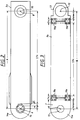
- FIG. 1 we start from a coordinate measuring machine of the type described, for example, in the aforementioned US Pat. No. 5,396,712 and the corresponding DE 42 38 139 A1, to which reference is made in full at this point. Not shown in FIG. 1 are the machine bed of this device with the workpiece table and the vertical z-column, on which a fork-shaped support (4) made of steel can be moved vertically in the direction of the arrow labeled (Z1).
- the bearings for a shaft (14) connecting the legs, which defines a first vertical axis of rotation (6), are inserted into the two legs of the carrier (4).
- a first arm (5) attached to the shaft (14) can be pivoted horizontally about this axis (6).
- the angle measuring system required to detect the swiveling movement is not shown here for the sake of clarity.
- the swivel arm (5) is also fork-shaped, the ends of the prongs (5a) and (5b) of the fork-shaped swivel arm again supporting the bearings for a second shaft (15).
- This shaft defines the second axis of rotation (8), which is at a distance (A) from the first axis of rotation (6) and is aligned parallel to the latter.
- a second swivel arm attached to the shaft (15) can be rotated about the axis (8) as illustrated by the arrow (Y).
- This second swivel arm consists of three parts and is designed in the form of a spring parallelogram in order to be able to manually deflect the vertical support (13) for the pushbutton of the device, as indicated by the arrow (Z2).
- the button has a resiliently mounted stylus (11) with a stylus ball (12) on its underside.
- the spring parallelogram is realized by two legs (9a) and (9b) arranged in parallel, the ends of which are connected by four joint springs (19a) and (19b) lying next to each other in pairs, once with the top and bottom of the carrier (13) and once with the Part (7) are connected, which is mounted on the shaft (15) between the legs (5a) and (5b) of the first swivel arm.
- the effective length of this part (5a), which is decisive for the thermal expansion, is 237.7 mm.
- the shaft (14), like the part (4), is made of steel with a coefficient of thermal expansion ⁇ 2 of approx. 10 ⁇ 10 -6 K -1 .
- the effective length L2 with which the shaft (14) contributes to the linear expansion of the swivel arm is 7.1 mm.
- the bearings for the shaft (15) are used, which consists of ceramic material, but at this point what the distance (A) between the axes (6) and (8) or their thermal linear expansion However, this does not have to be taken into account, since the center of the bearing remains centric regardless of the material type of the bearing and shaft.
- the situation is similar in the second articulated arm sketched in FIG. 3.
- the thermal expansion coefficient ⁇ 4 of the shaft (15) made of ceramic material must be taken into account, which is 1.5 ⁇ 10 -6 K -1 .
- the part (7) which surrounds the shaft (15) is also made of this ceramic material.
- This distance L4 is 23.6 mm.
- the button holder (13) also consists of this ceramic material and has an effective length L14 of 20.5 mm to be taken into account for the thermal expansion.
- the two legs (9a) and (9b) of the spring parallelogram again consist of the material CFRP with a negative coefficient of thermal expansion of -0.8 ⁇ 10 -6 K -1 in the direction of the path (B).
- the length L11 to be taken into account is 186 mm.
- the thermal expansion of the distance (B) between the axis of rotation (8) and the probe axis (10) is 2.86 ⁇ m in total, which is also negligible within the measuring accuracy of the device.
- An even better result can be achieved by shortening the steel springs (19) or lengthening the CFRP parts (9a / 9b).
- the middle part of the first swivel arm (5) connecting the two legs (5a) and (5b) is also made of CFRP, but this middle part is wound with respect to the position of the plastic reinforcing carbon fibers in such a way that with simultaneous good stability of the part in the direction of the first pivot axis (6) results in a positive thermal expansion coefficient ⁇ 1 'of approx. +1 ⁇ 10 -6 / K.
- the distance between the two bearings for the shaft (15) supporting legs (5a) and (5b) of the first swivel arm is of the same order of magnitude the same thermal expansion behavior as the shaft (15) made of ceramic material, so that no destructive forces result at this point either thermal expansion can be exerted on the bearings of the shaft (15).
Landscapes
- Physics & Mathematics (AREA)
- General Physics & Mathematics (AREA)
- Length Measuring Devices With Unspecified Measuring Means (AREA)
- A Measuring Device Byusing Mechanical Method (AREA)
Applications Claiming Priority (2)
| Application Number | Priority Date | Filing Date | Title |
|---|---|---|---|
| DE19534425 | 1995-09-16 | ||
| DE19534425A DE19534425A1 (de) | 1995-09-16 | 1995-09-16 | Koordinatenmeßgerät, dessen Taster über mehrere Drehachsen beweglich gelagert ist |
Publications (3)
| Publication Number | Publication Date |
|---|---|
| EP0763709A2 true EP0763709A2 (fr) | 1997-03-19 |
| EP0763709A3 EP0763709A3 (fr) | 1998-07-01 |
| EP0763709B1 EP0763709B1 (fr) | 2002-10-30 |
Family
ID=7772378
Family Applications (1)
| Application Number | Title | Priority Date | Filing Date |
|---|---|---|---|
| EP96113891A Expired - Lifetime EP0763709B1 (fr) | 1995-09-16 | 1996-08-30 | Machine de mesure de coordonnées à tête de mesure tournante autour de plusieurs axes |
Country Status (4)
| Country | Link |
|---|---|
| US (1) | US5890300A (fr) |
| EP (1) | EP0763709B1 (fr) |
| JP (1) | JP3684000B2 (fr) |
| DE (2) | DE19534425A1 (fr) |
Cited By (1)
| Publication number | Priority date | Publication date | Assignee | Title |
|---|---|---|---|---|
| WO2022140748A1 (fr) * | 2020-12-24 | 2022-06-30 | Sa08700334 | Machine de mesure de coordonnées portable ultra-légère et ultra-précise sensiblement insensible aux effets thermiques de l'ensemble palier |
Families Citing this family (14)
| Publication number | Priority date | Publication date | Assignee | Title |
|---|---|---|---|---|
| JP3633788B2 (ja) * | 1998-07-13 | 2005-03-30 | 株式会社ミツトヨ | 測定装置 |
| US6253458B1 (en) * | 1998-12-08 | 2001-07-03 | Faro Technologies, Inc. | Adjustable counterbalance mechanism for a coordinate measurement machine |
| USD423534S (en) * | 1999-02-19 | 2000-04-25 | Faro Technologies, Inc. | Articulated arm |
| US6298572B1 (en) | 2000-01-10 | 2001-10-09 | Mcauley Brian | Universal holding device for effectuating three dimensional measurement of a part and method of constructing such a holding device |
| US20040184039A1 (en) * | 2001-07-16 | 2004-09-23 | Ralf Christoph | Co-ordinate measuring device with additional heat source |
| GB0324519D0 (en) * | 2003-10-21 | 2003-11-26 | Renishaw Plc | Metrology instruments |
| CN101542227A (zh) * | 2006-11-30 | 2009-09-23 | 法罗技术股份有限公司 | 便携式坐标测量机 |
| JP5270384B2 (ja) * | 2009-01-15 | 2013-08-21 | 株式会社ミツトヨ | 直線案内機構および測定装置 |
| CN107250722A (zh) * | 2015-02-26 | 2017-10-13 | 马波斯S.P.A.公司 | 用于检查工件的尺寸和/或几何特征的系统及其相关的制造工艺 |
| EP4265231A3 (fr) | 2015-08-14 | 2023-12-20 | Alcon Inc. | Implant oculaire ayant un capteur de pression |
| US11566880B2 (en) * | 2017-04-13 | 2023-01-31 | Sa08700334 | Ultra-light and ultra-accurate portable coordinate measurement machine substantially immune to bearing assembly thermal effects |
| US10267614B2 (en) * | 2017-04-13 | 2019-04-23 | Sa08700334 | Ultra-light and ultra-accurate portable coordinate measurement machine |
| CN115461593B (zh) * | 2020-04-30 | 2023-08-29 | 株式会社东京精密 | 测量装置 |
| EP4407274A1 (fr) * | 2023-01-25 | 2024-07-31 | Hexagon Technology Center GmbH | Machine de mesure de coordonnées |
Family Cites Families (11)
| Publication number | Priority date | Publication date | Assignee | Title |
|---|---|---|---|---|
| US3077958A (en) * | 1961-09-05 | 1963-02-19 | United Aircraft Corp | Zero thermal expansion device |
| GB1059167A (en) * | 1962-10-18 | 1967-02-15 | Sogenique Service Ltd | Improvements in and relating to metrological apparatus |
| US3311986A (en) * | 1964-08-07 | 1967-04-04 | Technion Res & Dev Foundation | Compensated gauges for external dimensions |
| US3528206A (en) * | 1967-08-03 | 1970-09-15 | Canadian Patents Dev | Thermal expansion compensation device |
| US4282688A (en) * | 1979-07-05 | 1981-08-11 | The Perkin-Elmer Corporation | Adjustable CTE graphite-epoxy bar |
| US4761887A (en) * | 1986-08-29 | 1988-08-09 | Control Gaging, Inc. | Temperature insensitive gauge |
| DE3711070A1 (de) * | 1987-04-02 | 1988-11-24 | Heidenhain Gmbh Dr Johannes | Laengen- oder winkelmesseinrichtung |
| US4815213A (en) * | 1987-10-09 | 1989-03-28 | Brown & Sharpe Manufacturing Co. | Apparatus for temperature compensation of sensing means of a machine |
| US5095632A (en) * | 1990-06-15 | 1992-03-17 | Parker Hannifin Corporation | Composite structure unidirectionally stable with respect to thermal and moisture expansion |
| DE4238139C2 (de) * | 1992-11-12 | 2002-10-24 | Zeiss Carl | Koordinatenmeßgerät |
| US5402582A (en) * | 1993-02-23 | 1995-04-04 | Faro Technologies Inc. | Three dimensional coordinate measuring apparatus |
-
1995
- 1995-09-16 DE DE19534425A patent/DE19534425A1/de not_active Withdrawn
-
1996
- 1996-08-30 EP EP96113891A patent/EP0763709B1/fr not_active Expired - Lifetime
- 1996-08-30 DE DE59609831T patent/DE59609831D1/de not_active Expired - Fee Related
- 1996-09-13 JP JP24364696A patent/JP3684000B2/ja not_active Expired - Fee Related
- 1996-09-13 US US08/713,501 patent/US5890300A/en not_active Expired - Fee Related
Cited By (1)
| Publication number | Priority date | Publication date | Assignee | Title |
|---|---|---|---|---|
| WO2022140748A1 (fr) * | 2020-12-24 | 2022-06-30 | Sa08700334 | Machine de mesure de coordonnées portable ultra-légère et ultra-précise sensiblement insensible aux effets thermiques de l'ensemble palier |
Also Published As
| Publication number | Publication date |
|---|---|
| DE19534425A1 (de) | 1997-03-20 |
| EP0763709B1 (fr) | 2002-10-30 |
| JP3684000B2 (ja) | 2005-08-17 |
| EP0763709A3 (fr) | 1998-07-01 |
| DE59609831D1 (de) | 2002-12-05 |
| US5890300A (en) | 1999-04-06 |
| JPH09113258A (ja) | 1997-05-02 |
Similar Documents
| Publication | Publication Date | Title |
|---|---|---|
| EP0763709B1 (fr) | Machine de mesure de coordonnées à tête de mesure tournante autour de plusieurs axes | |
| EP0597299B1 (fr) | Dispositif de mesure de coordonnées | |
| DE2535347C2 (de) | Verfahren zum Messen von zylindrisch gestalteten Flächen | |
| DE2934347C2 (de) | Verfahren und Prüfgerät zum Prüfen des Zahnflankenprofils von Zahnrädern großen Durchmessers | |
| DE3740070A1 (de) | Dreh-schwenk-einrichtung fuer tastkoepfe von koordinatenmessgeraeten | |
| EP0456276A1 (fr) | Appareil pour mesurer les coordonnées | |
| DE3619643C2 (de) | Rohrbiegemaschine | |
| CH672838A5 (fr) | ||
| CH667916A5 (de) | Verfahren und mess-richtgeraet zur messung der geradheit und ebenheit. | |
| DE3406045A1 (de) | Abtastvorrichtung, welche am ende des querarmes eines mess- und anreissgeraetes anschliessbar ist | |
| DE3717541A1 (de) | Koordinatenmessvorrichtung | |
| DE2346031B1 (de) | Messkopf fuer Koordinatenmessmaschinen | |
| DE4308823C2 (de) | Messender Tastkopf für Koordinatenmeßgeräte | |
| DE1548305B2 (de) | Gerät zur Bestimmung der Oberflächenrauhigkeit | |
| EP2538168A1 (fr) | Dispositif de mesure pour pièces à usiner en flexion | |
| DE2953577C2 (de) | Zeichenmaschine mit Parallelführungsgestänge | |
| DE3441458C2 (fr) | ||
| DE3422161C2 (fr) | ||
| DD139454A1 (de) | Messkopf | |
| DE2532675A1 (de) | Messmethode fuer ein lager | |
| CH664012A5 (de) | Verfahren und vorrichtung zum vermessen eines werkstueckes. | |
| DE19861469B4 (de) | Verfahren zur Kalibrierung eines Tasters eines Koordinatenmessgerätes | |
| DE2636645C2 (de) | Taster für Längen-Meßmaschinen | |
| DE4303221C2 (de) | Verfahren zum Kalibrieren einer Werkzeugmaschine und Kalibrierwerkzeug | |
| DE4004486C2 (fr) |
Legal Events
| Date | Code | Title | Description |
|---|---|---|---|
| PUAI | Public reference made under article 153(3) epc to a published international application that has entered the european phase |
Free format text: ORIGINAL CODE: 0009012 |
|
| AK | Designated contracting states |
Kind code of ref document: A2 Designated state(s): DE FR GB IT |
|
| PUAL | Search report despatched |
Free format text: ORIGINAL CODE: 0009013 |
|
| AK | Designated contracting states |
Kind code of ref document: A3 Designated state(s): DE FR GB IT |
|
| 17P | Request for examination filed |
Effective date: 19981202 |
|
| 17Q | First examination report despatched |
Effective date: 20010704 |
|
| GRAG | Despatch of communication of intention to grant |
Free format text: ORIGINAL CODE: EPIDOS AGRA |
|
| GRAG | Despatch of communication of intention to grant |
Free format text: ORIGINAL CODE: EPIDOS AGRA |
|
| GRAH | Despatch of communication of intention to grant a patent |
Free format text: ORIGINAL CODE: EPIDOS IGRA |
|
| RAP1 | Party data changed (applicant data changed or rights of an application transferred) |
Owner name: CARL-ZEISS-STIFTUNG, TRADING AS CARL ZEISS Owner name: CARL ZEISS |
|
| GRAH | Despatch of communication of intention to grant a patent |
Free format text: ORIGINAL CODE: EPIDOS IGRA |
|
| GRAA | (expected) grant |
Free format text: ORIGINAL CODE: 0009210 |
|
| AK | Designated contracting states |
Kind code of ref document: B1 Designated state(s): DE FR GB IT |
|
| REG | Reference to a national code |
Ref country code: GB Ref legal event code: FG4D Free format text: NOT ENGLISH |
|
| REF | Corresponds to: |
Ref document number: 59609831 Country of ref document: DE Date of ref document: 20021205 |
|
| GBT | Gb: translation of ep patent filed (gb section 77(6)(a)/1977) |
Effective date: 20030120 |
|
| ET | Fr: translation filed | ||
| PLBE | No opposition filed within time limit |
Free format text: ORIGINAL CODE: 0009261 |
|
| STAA | Information on the status of an ep patent application or granted ep patent |
Free format text: STATUS: NO OPPOSITION FILED WITHIN TIME LIMIT |
|
| 26N | No opposition filed |
Effective date: 20030731 |
|
| REG | Reference to a national code |
Ref country code: GB Ref legal event code: 732E |
|
| PGFP | Annual fee paid to national office [announced via postgrant information from national office to epo] |
Ref country code: DE Payment date: 20080822 Year of fee payment: 13 |
|
| PGFP | Annual fee paid to national office [announced via postgrant information from national office to epo] |
Ref country code: IT Payment date: 20080825 Year of fee payment: 13 Ref country code: FR Payment date: 20080813 Year of fee payment: 13 |
|
| PGFP | Annual fee paid to national office [announced via postgrant information from national office to epo] |
Ref country code: GB Payment date: 20080821 Year of fee payment: 13 |
|
| GBPC | Gb: european patent ceased through non-payment of renewal fee |
Effective date: 20090830 |
|
| REG | Reference to a national code |
Ref country code: FR Ref legal event code: ST Effective date: 20100430 |
|
| PG25 | Lapsed in a contracting state [announced via postgrant information from national office to epo] |
Ref country code: FR Free format text: LAPSE BECAUSE OF NON-PAYMENT OF DUE FEES Effective date: 20090831 Ref country code: DE Free format text: LAPSE BECAUSE OF NON-PAYMENT OF DUE FEES Effective date: 20100302 |
|
| PG25 | Lapsed in a contracting state [announced via postgrant information from national office to epo] |
Ref country code: GB Free format text: LAPSE BECAUSE OF NON-PAYMENT OF DUE FEES Effective date: 20090830 |
|
| PG25 | Lapsed in a contracting state [announced via postgrant information from national office to epo] |
Ref country code: IT Free format text: LAPSE BECAUSE OF NON-PAYMENT OF DUE FEES Effective date: 20090830 |