EP0763732A2 - Anordnung für die Materialprüfung von Formteilen - Google Patents
Anordnung für die Materialprüfung von Formteilen Download PDFInfo
- Publication number
- EP0763732A2 EP0763732A2 EP96810575A EP96810575A EP0763732A2 EP 0763732 A2 EP0763732 A2 EP 0763732A2 EP 96810575 A EP96810575 A EP 96810575A EP 96810575 A EP96810575 A EP 96810575A EP 0763732 A2 EP0763732 A2 EP 0763732A2
- Authority
- EP
- European Patent Office
- Prior art keywords
- actuator
- sensor
- arrangement according
- disks
- excitation
- Prior art date
- Legal status (The legal status is an assumption and is not a legal conclusion. Google has not performed a legal analysis and makes no representation as to the accuracy of the status listed.)
- Granted
Links
Images


Classifications
-
- G—PHYSICS
- G01—MEASURING; TESTING
- G01N—INVESTIGATING OR ANALYSING MATERIALS BY DETERMINING THEIR CHEMICAL OR PHYSICAL PROPERTIES
- G01N29/00—Investigating or analysing materials by the use of ultrasonic, sonic or infrasonic waves; Visualisation of the interior of objects by transmitting ultrasonic or sonic waves through the object
- G01N29/22—Details, e.g. general constructional or apparatus details
- G01N29/24—Probes
-
- G—PHYSICS
- G01—MEASURING; TESTING
- G01M—TESTING STATIC OR DYNAMIC BALANCE OF MACHINES OR STRUCTURES; TESTING OF STRUCTURES OR APPARATUS, NOT OTHERWISE PROVIDED FOR
- G01M7/00—Vibration-testing of structures; Shock-testing of structures
- G01M7/02—Vibration-testing by means of a shake table
- G01M7/022—Vibration control arrangements, e.g. for generating random vibrations
-
- G—PHYSICS
- G01—MEASURING; TESTING
- G01N—INVESTIGATING OR ANALYSING MATERIALS BY DETERMINING THEIR CHEMICAL OR PHYSICAL PROPERTIES
- G01N29/00—Investigating or analysing materials by the use of ultrasonic, sonic or infrasonic waves; Visualisation of the interior of objects by transmitting ultrasonic or sonic waves through the object
- G01N29/04—Analysing solids
- G01N29/12—Analysing solids by measuring frequency or resonance of acoustic waves
-
- G—PHYSICS
- G01—MEASURING; TESTING
- G01N—INVESTIGATING OR ANALYSING MATERIALS BY DETERMINING THEIR CHEMICAL OR PHYSICAL PROPERTIES
- G01N29/00—Investigating or analysing materials by the use of ultrasonic, sonic or infrasonic waves; Visualisation of the interior of objects by transmitting ultrasonic or sonic waves through the object
- G01N29/22—Details, e.g. general constructional or apparatus details
- G01N29/227—Details, e.g. general constructional or apparatus details related to high pressure, tension or stress conditions
-
- G—PHYSICS
- G01—MEASURING; TESTING
- G01N—INVESTIGATING OR ANALYSING MATERIALS BY DETERMINING THEIR CHEMICAL OR PHYSICAL PROPERTIES
- G01N29/00—Investigating or analysing materials by the use of ultrasonic, sonic or infrasonic waves; Visualisation of the interior of objects by transmitting ultrasonic or sonic waves through the object
- G01N29/22—Details, e.g. general constructional or apparatus details
- G01N29/28—Details, e.g. general constructional or apparatus details providing acoustic coupling, e.g. water
-
- G—PHYSICS
- G01—MEASURING; TESTING
- G01N—INVESTIGATING OR ANALYSING MATERIALS BY DETERMINING THEIR CHEMICAL OR PHYSICAL PROPERTIES
- G01N2291/00—Indexing codes associated with group G01N29/00
- G01N2291/01—Indexing codes associated with the measuring variable
- G01N2291/014—Resonance or resonant frequency
-
- G—PHYSICS
- G01—MEASURING; TESTING
- G01N—INVESTIGATING OR ANALYSING MATERIALS BY DETERMINING THEIR CHEMICAL OR PHYSICAL PROPERTIES
- G01N2291/00—Indexing codes associated with group G01N29/00
- G01N2291/02—Indexing codes associated with the analysed material
- G01N2291/028—Material parameters
- G01N2291/02827—Elastic parameters, strength or force
-
- G—PHYSICS
- G01—MEASURING; TESTING
- G01N—INVESTIGATING OR ANALYSING MATERIALS BY DETERMINING THEIR CHEMICAL OR PHYSICAL PROPERTIES
- G01N2291/00—Indexing codes associated with group G01N29/00
- G01N2291/04—Wave modes and trajectories
- G01N2291/042—Wave modes
- G01N2291/0426—Bulk waves, e.g. quartz crystal microbalance, torsional waves
Definitions
- the invention relates to an arrangement for material testing of molded parts according to the preamble of claim 1.
- the object of the invention is to provide a suitable arrangement for the test method described, special care being taken to ensure that both the excitation of the vibration generator in shape and amplitude and its acoustic coupling for the reference part and the test object are the same and constant. Because only with constant excitation and coupling do the measured and recorded spectra give a clear and correct statement about the material condition of the test specimens or molded parts.
- An actuator / sensor arrangement on a piezoelectric / electromechanical basis as used, for example, in shock absorbers in vehicle construction for active chassis control (Akira FUKAMI et al., Development of Piezo-Electric Actuators and Sensors for Electronically Controlled Suspension, JSAE Review, Jap. Soc. Of Automotive Engineers, Vol 12, No 3 (1991), pp 48-52), is suitable in conjunction with a coupling element for the test method described as a compact and robust excitation and measurement arrangement, the measurement signals of which in the signal analyzer are simple can be analyzed and used for further purposes.
- a constant coupling can be achieved, for example, by means of a spring force, a hydraulic or pneumatic contact pressure or the contact pressure of a weight, such as a robot arm.
- means which trigger the excitation of the actuator only after an adjustable threshold value for the contact force of the assembly unit against the molded part is exceeded, this threshold value being determined by the sensor.
- the actuator and sensor mechanically in series, although a parallel arrangement of the two is also possible.
- the series arrangement has the advantage that the same coupling conditions are given for both. It is of secondary importance whether the sensor or the actuator is placed closer to the molded part in a coaxial arrangement.
- the sensor and actuator have different requirements - e.g. If the actuator is required to travel a relatively long distance when it is excited, it is advantageous if the sensor and actuator have different pretensioning forces, and a separately pretensioned sensor can additionally be acted upon by the pretensioning force for the actuator.
- Force sensors have proven particularly useful as sensors; however, the use of other sensors such as acceleration or sound emission sensors is also possible.
- the senor can advantageously consist of quartz disks. If high accuracy and relatively powerful signals are required, a sensor made of piezoceramic and quartz disks should be chosen.
- the structure of the actuator / sensor arrangement becomes mechanically simple if the actuator and sensor disks are designed as ring disks, which are under constant mechanical prestressing in one Housing can be mounted.
- Coupling the actuator / sensor arrangement to the molded part is facilitated if the assembly unit is provided with a handle for pressing onto the molded part.
- the coupling element is exchangeably connected to the actuator / sensor arrangement, optimal coupling conditions can be achieved for each application by varying the coupling elements.
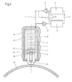
- the arrangement according to the invention according to FIG. 1 has a first actuator / sensor unit with a plurality of piezoceramic disks 1 as actuator 2, which are combined to form a columnar stack element. An electrical excitation voltage is supplied to them via a schematically indicated line 3.
- the excitation voltages are generated by a signal generator 4, which, as mentioned, can be designed as a pulse or frequency generator, for example. Its signals first reach a power amplifier 5 before they flow to the actuator 2.
- the actuator stack element 2 At its lower end, the actuator stack element 2, the disks 1 of which are prestressed in a housing 2, is connected, for example screwed, to a prestressed force measuring element 6.
- a coupling element 8 is detachably and interchangeably attached to the element 6.
- the force measuring element 6 consists of an upper part 31 and a lower part 32, between which a sensor 9 is clamped and held under a pretension, for example by a screw connection 7.
- the coupling element 8 can be made of steel, for example for a "hard” coupling, or of a plastic, for example Delrin, for a "soft" coupling.
- the senor 9 is an annular disk made of piezoceramic; Of course, as already mentioned, it can also be made from several disks and / or from quartz.
- the measurement signals of the sensor 9 are routed to a signal display 11 via a line 10.
- the signals first reach a charge amplifier 12 before being amplified, made visible in the display device 11 and fed to a possible further processing.
- the signals of the generator 4 can, if necessary, be branched off either before or after the amplifier 5 and can also be fed into the display device 11 via signal lines 13. If the excitation deviates from its target shape and / or amplitude, it is possible to correct the deviations via lines 14.
- the actual actuator / sensor unit 2, 6, 8 is enclosed by a, preferably cylindrical, basic housing 15 which, depending on the application, can be provided with a handle 16 on the outside or clamped in a robot arm (not shown).
- a handle 16 on the outside or clamped in a robot arm (not shown).
- the unit 2, 6, 8 is pressed with its housing 15 onto the part 18, the properties of which are to be determined, whereby, as already stated, actuator excitation may only take place after a threshold value for the contact pressure, for example from Display device 11 via line 14 is triggered.
- the arrangement according to FIG. 2 differs only in details from the above example.
- the sensor 9 is not arranged in a separate force measuring element, but as one or several disks integrated in the stack element of the actuator 2.
- the amplifiers 5 and 12 are accommodated in the basic housing of the unit 2, 6, 8, which is therefore divided into two sub-housings 19 and 20.
- the handle 16 has been dispensed with, so that the basic housing 19, 20 in the form shown can be inserted into a robot (not shown).
- actuator 2 and sensor 9 are mechanically arranged in series one behind the other, it being of secondary importance whether the actuator 2 or the sensor 9 are closer to the molded part 18.
- the row arrangement is also selected in the construction according to FIG. 3, in which the actuator 2 and the sensor 9 are accommodated in the annular space 21 of a pot-like housing 22 provided with an internal thread.
- the annular space 21 is open at the bottom and is closed off by a prestressing element 23, which is also annular.
- This biasing element 23 has an internal thread for mounting a coupling element, not shown. With the aid of a screw which passes through the internal thread of the housing 22, the unit 2, 9, 22, 23 can be mounted on top of a holding device (not shown) and pressed onto a molded part via a coupling element.
- the sensor 9 of the measuring element 6 and the actuator 2 are loaded with different preloads.
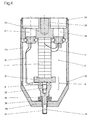
- Actuator 2 and sensor 9 are arranged together in the tubular housing 15, which for assembly reasons is divided into two parts 15a and 15b welded together at 30.
- the sensor 9 of the measuring element 6 is clamped between a preload screw 31 and a preload nut 32. It has a higher pretension than the stack of piezo disks 1 of the actuator 2, the disks 1 of which are clamped between the pretensioning screw 31 of the measuring element 6 and a connecting part 33 and additionally glued to these elements.
- the bias of the stack of piezo disks 1 is generated by one or more disc springs 35, which in turn have a Seal 36 are mounted in the housing part 15b.
- that of the plate spring 35 is added to its own separate pretension.
- the abutment for the force of the plate spring 35 forms a welded connection 34 between the housing part 15a and the connection part 33. This serves to accommodate electrical and mechanical connections of the actuator / sensor unit. It is therefore provided with two sockets 37 and 38 with different numbers of poles and a nut thread 39.
- the preload nut 32 of the measuring element 6 has a bolt-like extension 40 which passes through the housing part 15b and has a thread 41 on the outside; Interchangeable coupling elements 8 (FIG. 1) can be screwed onto this.
- the arrangement according to the invention ensures, on the one hand, constant excitation of the piezoelectric actuator for the acoustic vibrations and, on the other hand, a constant contact pressure when coupling the arrangement to the test specimen, so that changes in the vibration spectra of the vibrations induced in the test specimen, which are registered by the electromechanical sensor integrated in the arrangement, can be clearly assigned to the material of the molded part under investigation and its changed properties.
Landscapes
- Physics & Mathematics (AREA)
- General Physics & Mathematics (AREA)
- Biochemistry (AREA)
- Life Sciences & Earth Sciences (AREA)
- Chemical & Material Sciences (AREA)
- Analytical Chemistry (AREA)
- Health & Medical Sciences (AREA)
- General Health & Medical Sciences (AREA)
- Immunology (AREA)
- Pathology (AREA)
- Acoustics & Sound (AREA)
- Force Measurement Appropriate To Specific Purposes (AREA)
- Investigating Or Analyzing Materials By The Use Of Ultrasonic Waves (AREA)
Abstract
Description
- Die Erfindung betrifft eine Anordnung für Materialprüfung von Formteilen gemäss Oberbegriff von Anspruch 1.
- In der Fertigungstechnik von Formteilen, z.B. Blech- oder Kunststoffteilen, besteht häufig das Problem direkt nach dem Fertigungsprozess innerhalb kurzer Zeit, beispielsweise in einer Fertigungsstrasse während der kurzen Zeit zwischen zwei Bearbeitungsstationen, Formteile fehlerhafter Zusammensetzung - oder solche, die bei einer Umformung eine Beschädigung erlitten haben - zu erkennen und aus dem weiteren Produktionsprozess auszuscheiden.
- Es ist bekannt, dass "gute" und fehlerhafte Formteile in ihrem dynamischen Verhalten gegenüber akustischen Schwingungen, beispielsweise in ihrer Steifigkeit und in ihrem Dämpfungsverhalten, Unterschiede aufweisen. Darauf basierend ist vorgeschlagen worden (EP-Anmeldung 951166396 vom 23.10.1995), ein derartiges unterschiedliches Verhalten durch Messung der von einem Schwingungserzeuger angeregten, in das Formteil hineinfliessenden, akustischen Schwingungen zu ermitteln und danach eine Sortierung der Formteile vorzunehmen. Bei der Durchführung eines solchen Verfahrens wird beispielsweise das akustische Schwingungsspektrum eines "guten", d.h. fehlerfreien oder nur mit Fehlern innerhalb eines Toleranzbereiches behafteten, Formteils als Referenzspektrum benutzt, mit dem die Spektren der anderen Formteile verglichen werden. Über die Toleranzgrenze hinaus gehende Abweichungen in den Spektren der Prüflinge werden zum Ausscheiden des entsprechenden Prüflings benutzt.
- Aufgabe der Erfindung ist es, für das geschilderte Prüfverfahren eine geeignete Anordnung zur Verfügung zu stellen, wobei besonders darauf zu achten ist, dass sowohl die Anregung des Schwingungserzeugers in Form und Amplitude als auch seine akustische Ankopplung für Referenzteil und Prüfling gleich und konstant sind. Denn nur bei konstanter Anregung und Ankopplung ergeben die gemessenen und aufgezeichneten Spektren eine eindeutige und einwandfreie Aussage über den Materialzustand der Prüflinge, bzw. Formteile.
- Gelöst wird diese Aufgabe durch die im Kennzeichen von Anspruch 1 genannten Merkmale.
- Eine Aktuator/Sensoranordnung auf piezoelektrischer/elektromechanischer Basis, wie sie beispielsweise an sich bei Stossdämpfern im Fahrzeugbau für eine aktive Fahrwerksregelung (Akira FUKAMI et al., Development of Piezo-Electric Actuators and Sensors for Electronically Controlled Suspension, JSAE Review, Jap. Soc. Of Automotive Engineers, Vol 12, No 3 (1991), pp 48-52), bekannt ist, eignet sich in Verbindung mit einem Koppelelement für das geschilderte Prüfverfahren als kompakte und robuste Anregungs- und Messanordnung, deren Messignale in dem Signalanalysator auf einfache Weise analysiert und einer weiteren Verwendung zugeführt werden können.
- Durch die Mittel zur Erfassung der Signale des Generators, der als Anregungssignale für den Aktuator entweder Einzelimpulse oder über einen gewissen Frequenzbereich variable Schwingungen, z.B. Sinusschwingungen, konstanter Form und Amplitude erzeugt, wird eine für alle Formteile gleiche und konstante Anregung gewährleistet. Diese Erfassung kann beispielsweise in einem Programm für die Ausgabe einzelner Spannungsimpulse mit einer bestimmten Amplitude für jede Frequenz bestehen. Diese Mittel können auch darin bestehen, die Anregung des Aktuators zu messen und entsprechend zu korrigieren oder gegebenenfalls in einem Regelkreis in Form und Amplitude auf einem konstanten Wert zu halten.
- Eine konstante Ankopplung lässt sich beispielsweise durch eine Federkraft, einen hydraulischen oder pneumatischen Anpressdruck oder den Auflagedruck eines Gewichtes, wie etwa eines Roboterarmes erreichen. Vorteilhaft ist es jedoch, wenn Mittel vorgesehen sind, die die Anregung des Aktuators erst nach Überschreiten eines einstellbaren Schwellenwertes für die Anpresskraft der Montageeinheit an das Formteil auslösen, wobei die Ermittlung dieses Schwellenwertes durch den Sensor erfolgt. Durch diese Mittel erhält man eine Kontrolle über die Ankopplung und damit eine erhöhte Sicherheit für ihre und eine vergrösserte Genauigkeit bei ihrer Konstanz.
- Weiterhin hat es sich als zweckmässig erwiesen, Aktuator und Sensor mechanisch in Serie anzuordnen, obwohl eine Parallelanordnung beider ebenfalls möglich ist. Die Serienanordnung bringt jedoch den Vorteil, dass für beide die selben Ankopplungsbedingungen gegeben sind. Es ist dabei von untergeordneter Bedeutung, ob bei koaxialer Anordnung der Sensor oder der Aktuator näher zum Formteil plaziert ist.
- Da an Sensor und Aktuator unterschiedliche Anforderungen - z.B. wird vom Aktuator bei Anregung ein relativ langer Weg gefordert - gestellt werden, ist es vorteilhaft, wenn Sensor und Aktuator voneinander verschiedene Vorspannkräfte aufweisen, wobei ein separat vorgespannter Sensor zusätzlich von der Vorspannkraft für den Aktuator beaufschlagt sein kann.
- Als Sensoren haben sich Kraftsensoren besonders bewährt; die Anwendung von anderen Sensoren, wie Beschleunigungs- oder Schallemissions-Sensoren ist jedoch auch möglich.
- Kräftige Anregungsamplituden, d.h. grosse Schwingungswege des Aktuators, und relativ grosse Sensorsignale lassen sich erreichen, wenn Aktuator und Sensor aus Piezokeramikscheiben bestehen, wobei die Anregung zusätzlich erhöht werden kann, wenn der Aktuator ein Stapelelement aus einer Vielzahl von Piezokeramikscheiben ist. Durch Anwendung der Mehrschicht-Technologie können solche Stapelelemente mit hohen Stellwegen bei relativ niedrigen Spannungen hergestellt werden.
- Wird jedoch eine hohe Genauigkeit bei einer Schwellenwertbestimmung, beispielsweise für die Auslösung der Aktuatoranregung erst nach dem Erreichen einer bestimmten Anpresskraft, verlangt, so kann der Sensor mit Vorteil aus Quarzscheiben bestehen. Werden hohe Genauigkeit und relativ kräftige Signale verlangt, so wählt man zweckmässig einen Sensor aus Piezokeramik- und Quarzscheiben.
- Mechanisch einfach wird der Aufbau der Aktuator/Sensoranordnung, wenn die Aktuator- und die Sensorscheiben als Ringscheiben ausgebildet sind, die unter konstanter mechanischer Vorspannung in einem Gehäuse montiert werden können.
- Eine Ankopplung der Aktuator/Sensoranordnung an das Formteil wird erleichtert, wenn die Montageeinheit mit einem Handgriff zum Anpressen an das Formteil versehen ist.
- Wird das Koppelelement austauschbar mit der Aktuator/Sensoranordnung verbunden, so können für jeden Einsatz optimale Ankopplungsbedingungen durch Variation der Koppelelemente erreicht werden.
- Im folgenden wird die Erfindung anhand von Ausführungsbeispielen im Zusammenhang mit der Zeichnung näher erläutert.
- Es zeigen:
- Fig. 1
- in schematischer Darstellung eine erste Ausführungsform der erfindungsgemässen Anordnung
- Fig. 2
- in gleicher Darstellung eine Variante von Fig. 1
- Fig. 3
- ein weiteres Beispiel für eine Aktuator/Sensor-Einheit
- Fig. 4
- eine konstruktive Ausführungsform einer Aktuator/Sensoreinheit
- Die erfindungsgemässe Anordnung nach Fig. 1 weist eine erste Aktuator/Sensoreinheit mit einer Vielzahl von Piezokeramikscheiben 1 als Aktuator 2 auf, die zu einem säulenartigen Stapelelement zusammengefasst sind. Ihnen wird eine elektrische Anregungsspannung über eine schematisch angedeutete Leitung 3 zugeführt.
- Die Anregungsspannungen werden erzeugt von einem Signalgenerator 4, der beispielsweise, wie erwähnt, als Impuls- oder als Frequenzgenerator ausgebildet sein kann. Seine Signale gelangen zunächst auf einen Leistungsverstärker 5, ehe sie dem Aktuator 2 zufliessen.
- An seinem unteren Ende ist das Aktuator-Stapelelement 2, dessen Scheiben 1 in einem Gehäuse 2 vorgespannt sind, mit einem vorgespannten Kraftmesselement 6 verbunden, z.B. verschraubt. An das Element 6 ist lösbar und austauschbar ein Koppelelement 8 angesetzt. Das Kraftmesselement 6 besteht aus einem Oberteil 31 und einem Unterteil 32, zwischen denen ein Sensor 9 eingeklemmt und, z.B. durch eine Verschraubung 7, unter einer Vorspannung gehalten ist. Je nach den geforderten Ankoppelbedingungen kann das Koppelelement 8, beispielsweise für eine "harte" Ankopplung, aus Stahl oder, für eine "weiche" Ankopplung, aus einem Kunststoff, z.B. Delrin, bestehen.
- Der Sensor 9 ist in dem gezeigten Beispiel eine Ringscheibe aus Piezokeramik; selbstverständlich kann er auch, wie bereits erwähnt aus mehreren Scheiben und/oder aus Quarz hergestellt sein. Über eine Leitung 10 werden die Messignale des Sensors 9 auf eine Signalanzeige 11 geführt. Die Signale gelangen dabei zunächst auf einen Ladungsverstärker 12, ehe sie, verstärkt, in dem Anzeigegerät 11 sichtbar gemacht und einer eventuellen Weiterverarbeitung zugeführt werden.
- Für eine Erfassung der Aktuator-Anregung können, falls erforderlich, die Signale des Generators 4, wahlweise vor oder nach dem Verstärker 5 abgezweigt und über Signalleitungen 13 ebenfalls in das Anzeigegerät 11 eingespeist werden. Bei einer Abweichung der Anregung von ihrer Sollform und/oder Amplitude ist es möglich, die Abweichungen über Leitungen 14 zu korrigieren.
- Die eigentliche Aktuator/Sensoreinheit 2, 6, 8 ist umschlossen von einem, vorzugsweise zylindrischen, Grundgehäuse 15, das je nach Anwendungsfall aussen mit einem Handgriff 16 versehen oder in einen nicht gezeigten Roboterarm eingespannt sein kann. Für eine Prüfung eines Formteils 18 wird die Einheit 2, 6, 8 mit ihrem Gehäuse 15 auf das Teil 18 gepresst, dessen Eigenschaften ermittelt werden sollen, wobei, wie bereits ausgeführt, gegebenenfalls eine Aktuatoranregung erst nach Überschreiten eines Schwellenwertes für die Anpresskraft, beispielsweise vom Anzeigegerät 11 über die Leitung 14, ausgelöst wird.
- Die Anordnung nach Fig. 2 unterscheidet sich nur in Details von dem vorstehenden Beispiel. Bei ihr ist der Sensor 9 nicht in einem separaten Kraftmesselement angeordnet, sondern als eine oder mehrere Scheiben in das Stapelelement des Aktuators 2 integriert. Weiterhin sind die Verstärker 5 und 12 im Grundgehäuse der Einheit 2, 6, 8 untergebracht, das daher in zwei Teilgehäuse 19 und 20 unterteilt ist. Schliesslich ist der Handgriff 16 entfallen, so dass das Grundgehäuse 19, 20 in der gezeigten Form in einen nicht dargestellten Roboter eingesetzt werden kann.
- In beiden bisher gezeigten Aktuator/Sensoreinheiten 2, 6, 8 sind Aktuator 2 und Sensor 9 mechanisch in Reihe hintereinander angeordnet, wobei es von untergeordneter Bedeutung ist, ob der Aktuator 2 oder der Sensor 9 näher zum Formteil 18 liegen.
- Die Reihenanordnung ist auch bei der Konstruktion nach Fig. 3 gewählt, bei der der Aktuator 2 und der Sensor 9 im Ringraum 21 eines topfartigen, mit einem Innengewinde versehenen, Gehäuse 22 untergebracht sind. Der Ringraum 21 ist nach unten offen und von einem, ebenfalls ringförmigen, Vorspannelement 23 abgeschlossen. Dieses Vorspannelement 23 besitzt ein Innengewinde zur Montage eines nicht gezeigten Koppelelementes. Mit Hilfe einer Schraube, die das Innengewinde des Gehäuses 22 durchsetzt, kann die Einheit 2, 9, 22, 23 oben an eine nicht gezeigte Haltevorrichtung montiert und über ein Koppelelement auf ein Formteil gepresst werden.
- Bei der Konstruktion nach Fig. 4 sind der Sensor 9 des Messelementes 6 und der Aktuator 2 mit unterschiedlichen Vorspannungen belastet. Aktuator 2 und Sensor 9 sind gemeinsam in dem rohrförmigen Gehäuse 15 angeordnet, das aus Montagegründen in zwei miteinander bei 30 verschweisste Teile 15a und 15b unterteilt ist.
- Der Sensor 9 des Messelementes 6 ist zwischen einer Vorspannschraube 31 und einer Vorspannmutter 32 eingespannt. Er weist eine höhere Vorspannung auf als der Stapel der Piezoscheiben 1 des Aktuators 2, dessen Scheiben 1 zwischen der Vorspannschraube 31 des Messelementes 6 und einem Anschlussteil 33 eingeklemmt und zusätzlich mit diesen Elementen verklebt sind.
- Die Vorspannung des Stapels der Piezoscheiben 1 wird erzeugt von einer oder mehreren Tellerfedern 35, die ihrerseits über eine Dichtung 36 im Gehäuseteil 15b gelagert sind. Für den Sensor 9 addiert sich in diesem Ausführungsbeispiel zu seiner eigenen separaten Vorspannung diejenige der Tellerfeder 35.
- Das Widerlager für die Kraft der Tellerfeder 35 bildet eine Schweissverbindung 34 zwischen dem Gehäuseteil 15a und dem Anschlussteil 33. Dieses dient zur Aufnahme von elektrischen und mechanischen Anschlüssen der Aktuator/Sensoreinheit. In ihm sind daher zwei Steckerbuchsen 37 und 38 mit unterschiedlicher Polzahl und ein Muttergewinde 39 vorgesehen.
- Die Vorspannmutter 32 des Messelementes 6 weist eine bolzenartige Verlängerung 40 auf, die das Gehäuseteil 15b durchsetzt und aussen ein Gewinde 41 trägt; auf dieses sind austauschbare Koppelelemente 8 (Fig. 1) aufschraubbar.
- Bei vergleichenden Prüfverfahren für die Eigenschaften von Formteilen mit Hilfe ihres dynamischen Verhaltens gegenüber akustischen Schwingungen gewährleistet die erfindungsgemässe Anordnung zum einen eine konstante Anregung des piezoelektrischen Aktuators für die akustischen Schwingungen und zum zweiten eine konstante Anpresskraft bei der Ankopplung der Anordnung an den Prüfling, so dass Änderungen in den Schwingungsspektren der in den Prüfling induzierten Schwingungen, die von dem in die Anordnung integrierten elektromechanischen Sensor registriert werden, eindeutig dem Material des untersuchten Formteils und seinen geänderten Eigenschaften zugeordnet werden können.
Claims (12)
- Anordnung für die Materialprüfung von Formteilen zur Erkennung von Materialfehlern und/oder -eigenschaften, bei welcher Prüfung das Frequenzspektrum mechanischer Anregungsschwingungen eines zu prüfenden Formteiles (18) mit dem Frequenzspektrum eines gleichartigen Formteiles mit bekannten Eigenschaften als Referenzspektrum verglichen wird, gekennzeichnet- durch einen piezoelektrischen Aktuator (2), einen elektromechanischen Sensor (9) und ein Koppelelement (8, 32), die zu einer Montageeinheit vereinigt sind, ferner- durch einen Signalgenerator (4), der zur Aktuatoranregung Einzelimpulse oder über einen gewissen Bereich frequenzvariable Schwingungen konstanter Form und Amplitude erzeugt, weiterhin- durch Mittel zum Erfassen von Form und Amplitude der Aktuator-Anregung, und schliesslich- durch einen elektronischen Ladungsverstärker (12) mit Anzeigegerät (11), mit denen mindestens die vom Sensor gemessenen, mechanischen Anregungsschwingungen des Aktuators (2) erfasst werden.
- Anordnung nach Anspruch 1, gekennzeichnet durch Mittel (9, 11), die die Anregung des Aktuators erst nach Überschreiten eines Schwellenwertes für die Anpresskraft der Montageeinheit (2, 6, 8) an das Formteil (18) auslösen, wobei die Ermittlung der Anpresskraft durch den Sensor (9) erfolgt.
- Anordnung nach Anspruch 1 oder 2, dadurch gekennzeichnet, dass der Aktuator (2) und der Sensor (9) mechanisch in Serie angeordnet sind.
- Anordnung nach einem der Ansprüche 1 bis 3, dadurch gekennzeichnet, dass der Sensor (9) ein Kraftsensor ist.
- Anordnung nach einem der Ansprüche 1 bis 4, dadurch gekennzeichnet, dass der Aktuator (2) und der Sensor (9) aus Piezokeramikscheiben bestehen.
- Anordnung nach einem der Ansprüche 1 bis 4, dadurch gekennzeichnet, dass der Sensor (9) aus Piezokeramik- und aus Quarzkristallscheiben besteht.
- Anordnung nach Anspruch 5, dadurch gekennzeichnet, dass der Aktuator (2) ein Stapelelement aus einer Vielzahl von Piezokeramikscheiben (1) ist.
- Anordnung nach einem der Ansprüche 5 bis 7, dadurch gekennzeichnet, dass die Aktuator- und die Sensorscheiben als Ringscheiben ausgebildet sind.
- Anordnung nach einem der vorhergehenden Ansprüche, dadurch gekennzeichnet, dass die Montageeinheit (2, 6, 8) mit einem Handgriff (16) zum Anpressen an das Formteil (18) versehen ist.
- Anordnung nach einem der vorhergehenden Ansprüche, dadurch gekennzeichnet, dass das Koppelelement (8, 32) des Aktuators (2) austauschbar ist.
- Anordnung nach einem der vorhergehenden Ansprüche, dadurch gekennzeichnet, dass der Sensor (9) und der Aktuator (2) von einander verschiedene Vorspannkräfte aufweisen.
- Anordnung nach Anspruch 11, dadurch gekennzeichnet, dass der separat vorgespannte Sensor (9) zusätzlich mit der Vorspannkraft für den Aktuator beaufschlagt ist.
Applications Claiming Priority (2)
| Application Number | Priority Date | Filing Date | Title |
|---|---|---|---|
| CH02602/95A CH690600A5 (de) | 1995-09-15 | 1995-09-15 | Anordnung für die Materialprüfung von Formteilen. |
| CH2602/95 | 1995-09-15 |
Publications (3)
| Publication Number | Publication Date |
|---|---|
| EP0763732A2 true EP0763732A2 (de) | 1997-03-19 |
| EP0763732A3 EP0763732A3 (de) | 1999-04-28 |
| EP0763732B1 EP0763732B1 (de) | 2008-06-11 |
Family
ID=4237453
Family Applications (1)
| Application Number | Title | Priority Date | Filing Date |
|---|---|---|---|
| EP96810575A Expired - Lifetime EP0763732B1 (de) | 1995-09-15 | 1996-09-03 | Anordnung für die akustische Materialprüfung von Formteilen |
Country Status (4)
| Country | Link |
|---|---|
| US (1) | US5728937A (de) |
| EP (1) | EP0763732B1 (de) |
| CH (1) | CH690600A5 (de) |
| DE (1) | DE59611476D1 (de) |
Cited By (2)
| Publication number | Priority date | Publication date | Assignee | Title |
|---|---|---|---|---|
| WO2012112898A1 (en) * | 2011-02-18 | 2012-08-23 | Rolls-Royce Corporation | Detection and measurement of defect size and shape using ultrasonic fourier -transformed waveforms |
| US10690634B2 (en) | 2010-02-18 | 2020-06-23 | Rolls-Royce Corporation | Ultrasonic measurement and determination of crystallographic texture with respect to position |
Families Citing this family (8)
| Publication number | Priority date | Publication date | Assignee | Title |
|---|---|---|---|---|
| AU5313199A (en) * | 1998-06-25 | 2000-01-10 | Lci/Smartpen, N.V. | Systems and methods for measuring forces using piezoelectric transducers |
| EP1312916B1 (de) * | 2000-08-23 | 2009-04-08 | Mitsubishi Denki Kabushiki Kaisha | Vorrichtung zur zerstörungsfreien akustischen inspektion |
| US6556028B1 (en) | 2001-05-07 | 2003-04-29 | Storage Test Solutions, Inc. | Method and apparatus for detecting defects in piezoelectric actuators |
| DE10133510C1 (de) * | 2001-07-10 | 2002-11-28 | Siemens Ag | Fehlererkennung in Körpern aus spröden Materialien |
| FR2943136B1 (fr) * | 2009-03-12 | 2011-05-06 | Eads Europ Aeronautic Defence | Dispositif et procede de controle non-destructif par ultrasons de structures complexes. |
| GB201417162D0 (en) * | 2014-09-29 | 2014-11-12 | Renishaw Plc | Inspection appartus |
| GB201417164D0 (en) * | 2014-09-29 | 2014-11-12 | Renishaw Plc | Measurement Probe |
| US10557832B2 (en) * | 2017-04-28 | 2020-02-11 | GM Global Technology Operations LLC | Portable acoustic apparatus for in-situ monitoring of a weld in a workpiece |
Family Cites Families (9)
| Publication number | Priority date | Publication date | Assignee | Title |
|---|---|---|---|---|
| US3307393A (en) * | 1963-12-23 | 1967-03-07 | Ingersoll Rand Co | Stress measuring device |
| US3935484A (en) * | 1974-02-25 | 1976-01-27 | Westinghouse Electric Corporation | Replaceable acoustic transducer assembly |
| AT379898B (de) * | 1982-05-12 | 1986-03-10 | List Hans | Einrichtung zur aufnahme von koerperschallschwingungen |
| US4479386A (en) * | 1983-02-10 | 1984-10-30 | The United States Of America As Represented By The Administrator Of The National Aeronautics And Space Administration | Insulation bonding test system |
| US4519245A (en) * | 1983-04-05 | 1985-05-28 | Evans Herbert M | Method and apparatus for the non-destructive testing of materials |
| GB2262604A (en) * | 1991-12-16 | 1993-06-23 | Shifeng Liu | Acousto-ultrasonic testing instrument with coupling condition measurement |
| US5242512A (en) * | 1992-03-13 | 1993-09-07 | Alloying Surfaces, Inc. | Method and apparatus for relieving residual stresses |
| US5365457A (en) * | 1992-10-19 | 1994-11-15 | The United States Of America As Represented By The Secretary Of The Navy | In situ dynamic material property measurement system |
| DE9316822U1 (de) * | 1993-11-05 | 1994-06-01 | Albatros Applied Technologies Gmbh, 41466 Neuss | Prüfvorrichtung für die zerstörungsfreie Werkstoffprüfung |
-
1995
- 1995-09-15 CH CH02602/95A patent/CH690600A5/de not_active IP Right Cessation
-
1996
- 1996-09-03 DE DE59611476T patent/DE59611476D1/de not_active Expired - Fee Related
- 1996-09-03 EP EP96810575A patent/EP0763732B1/de not_active Expired - Lifetime
- 1996-09-11 US US08/712,200 patent/US5728937A/en not_active Expired - Fee Related
Cited By (3)
| Publication number | Priority date | Publication date | Assignee | Title |
|---|---|---|---|---|
| US10690634B2 (en) | 2010-02-18 | 2020-06-23 | Rolls-Royce Corporation | Ultrasonic measurement and determination of crystallographic texture with respect to position |
| WO2012112898A1 (en) * | 2011-02-18 | 2012-08-23 | Rolls-Royce Corporation | Detection and measurement of defect size and shape using ultrasonic fourier -transformed waveforms |
| US9753014B2 (en) | 2011-02-18 | 2017-09-05 | Rolls-Royce Corporation | Detection and measurement of defect size and shape using ultrasonic fourier-transformed waveforms |
Also Published As
| Publication number | Publication date |
|---|---|
| EP0763732A3 (de) | 1999-04-28 |
| US5728937A (en) | 1998-03-17 |
| CH690600A5 (de) | 2000-10-31 |
| DE59611476D1 (de) | 2008-07-24 |
| EP0763732B1 (de) | 2008-06-11 |
Similar Documents
| Publication | Publication Date | Title |
|---|---|---|
| EP0883983B1 (de) | Sensor für Erntemaschinen | |
| EP0386035B1 (de) | Einrichtung zur funktionskontrolle von beschleunigungssensoren | |
| DE19621449C2 (de) | Vibrationsresonator, Verfahren zum Betreiben eines solchen Vibrationsresonators und Vibrations-Füllstand-Grenzschalter mit einem solchen Vibrationsresonator | |
| EP0491002B1 (de) | Verfahren und Vorrichtung zur zerstörungsfreien Ermittlung des Vorspannungszustandes ferromagnetischer Verbindungselemente | |
| DE69937858T2 (de) | Verfahren und Vorrichtung zur Messung von Vibrationswellen | |
| EP0763732B1 (de) | Anordnung für die akustische Materialprüfung von Formteilen | |
| EP2769186A1 (de) | Hohlprofil-aufnehmer | |
| DE3930314A1 (de) | Piezoelektrischer sensor zur ueberwachung einer kinetischen bewegungsgroesse | |
| DE69820253T2 (de) | Erdverankerungs-Testsystem | |
| EP0902267A2 (de) | Beschleunigungskompensierter Druckaufnehmer | |
| DE102011053325A1 (de) | Prüfstand für die dynamische Überprüfung einer einzelnen Fahrwerkskomponente oder eines vollständigen Achssystems eines Kraftfahrzeugs, sowie Verfahren zum Überprüfen auf Selbigem | |
| DE2049550A1 (de) | Prüfeinrichtung fur Fahrzeugfederun gen | |
| EP3899486B1 (de) | Vorrichtung und verfahren zur ermittlung mechanischer eigenschaften eines prüfkörpers | |
| CH683718A5 (de) | Kombinierter Kraft-, Dehnungs- und Schallemissionsaufnehmer. | |
| DE4011910C2 (de) | ||
| CH683949A5 (de) | Verfahren und Apparat zur Messung der dynamischen Charakteristiken eines Stoss-Accelerometers. | |
| AT521572B1 (de) | Gleitlageranordnung | |
| DE3740598A1 (de) | Schwingeinheit fuer fuellstand-vibrations-grenzschalter | |
| CH680752A5 (de) | ||
| EP2877829A1 (de) | Prüfsystem zur dynamischen und/oder zyklischen belastungsprüfung einer probe | |
| DE102004045528B4 (de) | Vibrationssensor | |
| DE3808481C2 (de) | Vorrichtung zur Feststellung eines bestimmten Füllstandes in einem Behälter | |
| DE102016012564A1 (de) | Verbindungselement mit integriertem Sensor | |
| DE69926646T2 (de) | Gepulstes gaseinlassventil mit steuerbarer schliessenergie für massenspektrometer | |
| EP3444605B1 (de) | Ultraschallmikrofon mit selbsttest |
Legal Events
| Date | Code | Title | Description |
|---|---|---|---|
| PUAI | Public reference made under article 153(3) epc to a published international application that has entered the european phase |
Free format text: ORIGINAL CODE: 0009012 |
|
| AK | Designated contracting states |
Kind code of ref document: A2 Designated state(s): DE FR GB IT |
|
| PUAL | Search report despatched |
Free format text: ORIGINAL CODE: 0009013 |
|
| AK | Designated contracting states |
Kind code of ref document: A3 Designated state(s): DE FR GB IT |
|
| 17P | Request for examination filed |
Effective date: 19990713 |
|
| RAP1 | Party data changed (applicant data changed or rights of an application transferred) |
Owner name: KISTLER HOLDING AG |
|
| 17Q | First examination report despatched |
Effective date: 20060814 |
|
| GRAP | Despatch of communication of intention to grant a patent |
Free format text: ORIGINAL CODE: EPIDOSNIGR1 |
|
| RTI1 | Title (correction) |
Free format text: DEVICE FOR THE ACOUSTIC MATERIAL INSPECTION OF MOLDED ARTICLES |
|
| GRAS | Grant fee paid |
Free format text: ORIGINAL CODE: EPIDOSNIGR3 |
|
| GRAA | (expected) grant |
Free format text: ORIGINAL CODE: 0009210 |
|
| AK | Designated contracting states |
Kind code of ref document: B1 Designated state(s): DE FR GB IT |
|
| REG | Reference to a national code |
Ref country code: GB Ref legal event code: FG4D Free format text: NOT ENGLISH |
|
| REF | Corresponds to: |
Ref document number: 59611476 Country of ref document: DE Date of ref document: 20080724 Kind code of ref document: P |
|
| PGFP | Annual fee paid to national office [announced via postgrant information from national office to epo] |
Ref country code: IT Payment date: 20080925 Year of fee payment: 13 Ref country code: FR Payment date: 20080912 Year of fee payment: 13 |
|
| PGFP | Annual fee paid to national office [announced via postgrant information from national office to epo] |
Ref country code: GB Payment date: 20080918 Year of fee payment: 13 |
|
| PGFP | Annual fee paid to national office [announced via postgrant information from national office to epo] |
Ref country code: DE Payment date: 20080919 Year of fee payment: 13 |
|
| PLBE | No opposition filed within time limit |
Free format text: ORIGINAL CODE: 0009261 |
|
| STAA | Information on the status of an ep patent application or granted ep patent |
Free format text: STATUS: NO OPPOSITION FILED WITHIN TIME LIMIT |
|
| 26N | No opposition filed |
Effective date: 20090312 |
|
| GBPC | Gb: european patent ceased through non-payment of renewal fee |
Effective date: 20090903 |
|
| REG | Reference to a national code |
Ref country code: FR Ref legal event code: ST Effective date: 20100531 |
|
| PG25 | Lapsed in a contracting state [announced via postgrant information from national office to epo] |
Ref country code: FR Free format text: LAPSE BECAUSE OF NON-PAYMENT OF DUE FEES Effective date: 20090930 Ref country code: DE Free format text: LAPSE BECAUSE OF NON-PAYMENT OF DUE FEES Effective date: 20100401 |
|
| PG25 | Lapsed in a contracting state [announced via postgrant information from national office to epo] |
Ref country code: GB Free format text: LAPSE BECAUSE OF NON-PAYMENT OF DUE FEES Effective date: 20090903 |
|
| PG25 | Lapsed in a contracting state [announced via postgrant information from national office to epo] |
Ref country code: IT Free format text: LAPSE BECAUSE OF NON-PAYMENT OF DUE FEES Effective date: 20090903 |