EP0763837A1 - Dispositif de commutation - Google Patents
Dispositif de commutation Download PDFInfo
- Publication number
- EP0763837A1 EP0763837A1 EP96118557A EP96118557A EP0763837A1 EP 0763837 A1 EP0763837 A1 EP 0763837A1 EP 96118557 A EP96118557 A EP 96118557A EP 96118557 A EP96118557 A EP 96118557A EP 0763837 A1 EP0763837 A1 EP 0763837A1
- Authority
- EP
- European Patent Office
- Prior art keywords
- outer housing
- switching device
- switch
- recess
- web
- Prior art date
- Legal status (The legal status is an assumption and is not a legal conclusion. Google has not performed a legal analysis and makes no representation as to the accuracy of the status listed.)
- Granted
Links
- 239000004033 plastic Substances 0.000 claims description 2
- 239000011347 resin Substances 0.000 abstract description 7
- 229920005989 resin Polymers 0.000 abstract description 7
- 238000007789 sealing Methods 0.000 abstract description 6
- 238000000465 moulding Methods 0.000 abstract 1
- 239000002184 metal Substances 0.000 description 15
- 210000002105 tongue Anatomy 0.000 description 13
- 230000002349 favourable effect Effects 0.000 description 5
- 238000005266 casting Methods 0.000 description 4
- 238000003780 insertion Methods 0.000 description 3
- 230000037431 insertion Effects 0.000 description 3
- 239000000463 material Substances 0.000 description 3
- 238000009434 installation Methods 0.000 description 2
- 229910001369 Brass Inorganic materials 0.000 description 1
- 239000011324 bead Substances 0.000 description 1
- 239000010951 brass Substances 0.000 description 1
- 239000004020 conductor Substances 0.000 description 1
- 238000011161 development Methods 0.000 description 1
- 230000018109 developmental process Effects 0.000 description 1
- 238000002372 labelling Methods 0.000 description 1
- 238000003754 machining Methods 0.000 description 1
- 230000000149 penetrating effect Effects 0.000 description 1
- 238000004382 potting Methods 0.000 description 1
- 230000001681 protective effect Effects 0.000 description 1
- 229920001169 thermoplastic Polymers 0.000 description 1
- 239000004416 thermosoftening plastic Substances 0.000 description 1
Images





Classifications
-
- H—ELECTRICITY
- H02—GENERATION; CONVERSION OR DISTRIBUTION OF ELECTRIC POWER
- H02B—BOARDS, SUBSTATIONS OR SWITCHING ARRANGEMENTS FOR THE SUPPLY OR DISTRIBUTION OF ELECTRIC POWER
- H02B1/00—Frameworks, boards, panels, desks, casings; Details of substations or switching arrangements
- H02B1/015—Boards, panels, desks; Parts thereof or accessories therefor
- H02B1/04—Mounting thereon of switches or of other devices in general, the switch or device having, or being without, casing
- H02B1/052—Mounting on rails
-
- H—ELECTRICITY
- H01—ELECTRIC ELEMENTS
- H01H—ELECTRIC SWITCHES; RELAYS; SELECTORS; EMERGENCY PROTECTIVE DEVICES
- H01H11/00—Apparatus or processes specially adapted for the manufacture of electric switches
- H01H11/0006—Apparatus or processes specially adapted for the manufacture of electric switches for converting electric switches
-
- H—ELECTRICITY
- H01—ELECTRIC ELEMENTS
- H01H—ELECTRIC SWITCHES; RELAYS; SELECTORS; EMERGENCY PROTECTIVE DEVICES
- H01H13/00—Switches having rectilinearly-movable operating part or parts adapted for pushing or pulling in one direction only, e.g. push-button switch
- H01H13/02—Details
- H01H13/04—Cases; Covers
- H01H13/06—Dustproof, splashproof, drip-proof, waterproof or flameproof casings
- H01H13/063—Casings hermetically closed by a diaphragm through which passes an actuating member
-
- H—ELECTRICITY
- H01—ELECTRIC ELEMENTS
- H01H—ELECTRIC SWITCHES; RELAYS; SELECTORS; EMERGENCY PROTECTIVE DEVICES
- H01H13/00—Switches having rectilinearly-movable operating part or parts adapted for pushing or pulling in one direction only, e.g. push-button switch
- H01H13/02—Details
- H01H13/26—Snap-action arrangements depending upon deformation of elastic members
- H01H13/28—Snap-action arrangements depending upon deformation of elastic members using compression or extension of coil springs
- H01H13/285—Snap-action arrangements depending upon deformation of elastic members using compression or extension of coil springs having a symmetrical configuration
-
- H—ELECTRICITY
- H02—GENERATION; CONVERSION OR DISTRIBUTION OF ELECTRIC POWER
- H02B—BOARDS, SUBSTATIONS OR SWITCHING ARRANGEMENTS FOR THE SUPPLY OR DISTRIBUTION OF ELECTRIC POWER
- H02B1/00—Frameworks, boards, panels, desks, casings; Details of substations or switching arrangements
- H02B1/015—Boards, panels, desks; Parts thereof or accessories therefor
- H02B1/04—Mounting thereon of switches or of other devices in general, the switch or device having, or being without, casing
-
- H—ELECTRICITY
- H02—GENERATION; CONVERSION OR DISTRIBUTION OF ELECTRIC POWER
- H02B—BOARDS, SUBSTATIONS OR SWITCHING ARRANGEMENTS FOR THE SUPPLY OR DISTRIBUTION OF ELECTRIC POWER
- H02B1/00—Frameworks, boards, panels, desks, casings; Details of substations or switching arrangements
- H02B1/26—Casings; Parts thereof or accessories therefor
-
- H—ELECTRICITY
- H02—GENERATION; CONVERSION OR DISTRIBUTION OF ELECTRIC POWER
- H02B—BOARDS, SUBSTATIONS OR SWITCHING ARRANGEMENTS FOR THE SUPPLY OR DISTRIBUTION OF ELECTRIC POWER
- H02B1/00—Frameworks, boards, panels, desks, casings; Details of substations or switching arrangements
- H02B1/015—Boards, panels, desks; Parts thereof or accessories therefor
- H02B1/04—Mounting thereon of switches or of other devices in general, the switch or device having, or being without, casing
- H02B1/041—Mechanical coupling for side-by-side mounted apparatus
Definitions
- the invention relates to a switching device with the features of the preamble of claims 1 and 2.
- a device of this type known from DE-U-8908871 has a switch which is cast in a chamber of an outer housing with casting resin.
- the switch can be actuated by means of an actuator releasably attached to the outer housing via an axially displaceable plunger.
- the switching device can be inserted into a holding frame of a mounting foot and can be held by means of a snap fastening via terminal housings provided on the narrow sides of the housing.
- the object of the invention is to develop a switching device with the features of the preamble of claims 1 and 2 in such a way that precise positioning and secure locking is achieved with simple means for a direct connection of a plurality of outer housings.
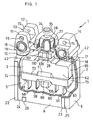
- the switching device 1 has an outer housing 2 and a switch 3 with a switching housing 4 which is mounted in a chamber 5 of the outer housing 2.
- the essentially rectangular outer housing 2 has two broad side walls 6, 7 and two narrow side walls 8, 9 and an upper wall 10 which delimit the chamber 5 which is open towards the bottom.
- Two fastening bumps 11, 12, between which there is a distance 13, can be formed on the top wall 10 in the vicinity of the one narrow side wall 8.
- a single fastening bump 14 can be provided on the upper wall 10, which is located approximately in the plane of the distance 13 of the opposite fastening bumps 11, 12.
- a metal bushing 16 extending parallel to this can be mounted in a bore in the outer housing 2 in the vicinity of the one narrow side wall 8.
- a further metal bushing 17 can be mounted in a bore under the one fastening bump 14.
- the length of the metal bushings 16, 17 is dimensioned such that it is substantially equal to the width of the outer housing 2, measured between the two broad side walls 6, 7. Fastening screws can be inserted through the metal bushings 16, 17 and tightened for secure fastening with high torque, without deformation or cold flow of the outer housing 2, which is made of plastic, preferably thermoplastic, can occur.
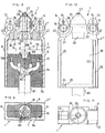
- the two metal bushings 16, 17 are completely identical and have a preferably tubular projection 18 at one end and a recess 19 preferably formed by an annular recess at the opposite end.
- the metal bushings 16, 17 are, however, mounted in opposite directions in the outer housing 2 , that is, in the plane of the broad side wall 6, for example, the recess 19 of one metal bushing 16 and the projection 18 of the other metal bushing 17 are located, while in the plane of the opposite broad side wall 7, for example the projection 18 of the one metal bushing 16 and the recess 19 the other metal bushing 17 are provided.
- the metal bushings 16, 17 can expediently be held in the bores of the outer housing 2 in a self-retaining manner, that is, secured against falling out.
- two or more switching devices 1 can be lined up exactly by the socket projection 18 of one switching device engaging in the socket recess 19 of the other switching device and likewise the socket projection 18 of the other switching device engaging in the socket recess 19 of the one switching device.
- the part-circular web parts 21 encompass the part-circular webs 20, so that there is multiple positive locking of the switchable devices that can be packaged or strung together, and an exact alignment and positioning of the structural units is always ensured.
- the webs 22, 23 and the depressions 24, 25 can preferably be formed on the lower housing part, that is to say in the region of the chamber 5, on the broad side walls 6, 7.
- the webs 22, 23 and the depressions 24, 25 can extend in the longitudinal direction of the outer housing 2, wherein one web 22 can directly adjoin the housing corner, while the other web 23 is spaced approximately as far from the other housing corner as the one Bridge 22 is wide.
- a further, preferably shorter web part 26 can be integrally formed at a distance from the one web 22.
- a web 23 engages between the web 22 and the web Web part 26 located recess 24 and at the same time a web 22 engages in the recess 25 formed between the housing corner and the web 23, whereby an exact positive positioning of the structural units is also achieved without special alignment or adjustment work having to be carried out.
- an actuating plunger 27 can be provided, which is axially displaceably mounted in the upper wall 10 in the middle between the two metal bushings 16, 17 in a cylinder 28 formed on the upper wall 10.
- the actuating plunger 27 can expediently be made of a metal, preferably brass, and have an annular collar 29 which is supported on the inside of the outer housing 2 between two housing wall parts 30, 31 on the underside of the cylinder 28. To save material and form a stable top wall, it may be expedient to provide an annular groove 32 surrounding the cylinder 28 in the top wall 10.
- a circumferential groove 33 can also be formed on the end region of the actuating plunger 27 protruding from the cylinder 28, into which a retaining collar 34 of a dome-shaped rubber-elastic protective cap 35 engages tightly, which covers the actuating plunger 27, the cylinder 28 and the annular groove 32 and with a bead 36 lies tightly on the top wall 10 of the outer housing 2.
- the outer housing 2 In order to achieve a high level of strength and perfect dimensional stability of the outer housing 2 with the least possible use of material, it may be expedient to provide largely identical housing wall thicknesses and, in particular, to form stiffening ribs 37 with grooves 38 in between in the upper region of the outer housing 2 or chamber 5.
- the outer housing 2 on at least one of the broad side walls 6, 7 on the outside Have labeling field 39 on which, for example, the company name, the device type, the approval number and technical data can be attached, in particular printed.
- a particularly advantageous fastening of the switching device 1 can consist in inserting the latter into a cold frame 40 or a mounting foot 41.
- a snap fastening part 42 on the outer housing 2, preferably on both narrow side walls 8, 9, which can be a snap recess, preferably designed as a rectangular groove.
- a counterpart 43 preferably a bead-shaped snap-in projection, can snap in a positive-locking manner, which can be integrally formed on a resilient tongue 44 of the holding frame 40 or the mounting foot 41.
- the holding frame 40 can be snapped, for example, on a rear of the control cabinet to commercially available actuators, such as buttons, shift levers and the like, and can be designed such that one or more switching devices 1 can optionally be arranged next to one another.
- the tongues 44 When the switching device 1 is inserted into the holding frame 40, the tongues 44 initially bend slightly apart. As soon as the switching device 1 is in the end position, the counterparts 43 of the tongues 44 snap into the snap recesses 42 due to the restoring force of the tongues 44, so that an absolutely firm hold is ensured. To release the switching device 1 from the holding frame 40, the tongues 44 can be pressed, for example with a screwdriver or the like, so far that the snap connection disengages.
- the switching device 1 is inserted into the mounting base 41 in exactly the same way as in the holding frame 40.
- the release from the mounting base 41 can also be carried out with the aid of a screwdriver.
- the mounting foot 41 can have a C-shaped foot part 45, in which a fastening slide 46 can be mounted and which engages over the striving edge parts 47 of an approximately U-shaped rail 48.
- a clip recess 49 on the outer housing 2, to which an accessory 50, in particular an overtravel actuator, can be detachably attached.
- the clip recess 49 can preferably be arranged on both broad side walls 6, 7 and be rectangular.
- a slide-on slope 51 can be provided in the region of the upper wall 10 for simple fastening of the overtravel actuator 50.
- the clip recess 49 of the broad side wall 6, 7 and the snap recess 42 of the narrow side wall 8, 9 can expediently lie in one and the same plane, and preferably in the between the metal bushing 16, 17 mounted in the upper part of the outer housing 2 and the upper end of the Outer housing 2 molded web 22, 23 existing clearance area.
- the overtravel actuator 50 may have a preferably rectangular frame 52, in which a lifting part 53 inserted from above, which may also be rectangular and may have a cover plate 54, is axially displaceably mounted.
- a lifting part 53 inserted from above, which may also be rectangular and may have a cover plate 54, is axially displaceably mounted.
- two spaced-apart side walls 55, 56 can be formed, each of which can have a clip nose 57 protruding on the inside of the side walls 55, 56.
- the overtravel actuator 50 is plugged onto the outer housing 2
- the side walls 55, 56 slide over with the clip lugs 57 the slip-on slope 51, so that in the end position the side walls 55, 56 abut the broad side walls 6, 7 and the clip lugs 57 engage in the clip recesses 49 in a positive manner.
- the side walls 55, 56 can be bent slightly outwards, so that the clip lugs 57 are disengaged and the overtravel actuator 50 can be pulled off towards the top.
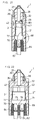
- the electrical switch 3 can expediently be designed both as a single switch 3 'and as a double switch 3' ', each actual switch having four connecting tongues 58, 59, 60, 61 which are led out of the switch housing 4 on the underside of the switch and expediently in in a row.
- the switch housing 4 can also be designed as a substantially rectangular body and have two broad side walls 62, 63, two narrow side walls 64, 65, a lower wall 66 and a roof wall 67.
- a latching connection 68 can be provided, by means of which the switch 3 is held immovably and precisely aligned in a defined position in the outer housing 2.
- the latching connection 68 can preferably consist of a latching recess 69 and a latching projection 70 which engages in the latching recess 69 in a form-fitting manner.
- the latching recess 69 may be preferably on the outside on both broad side walls 62, 63 and the latching projection 70 on the inside preferably on both broad side walls 6, 7 of the Provide outer housing 2.
- an insertion bevel 71 can expediently be provided, which can preferably be arranged on the switch housing 4 in one plane above the latching recess 69. It may also be favorable to preferably form the insertion bevel 71 in the chamber 5 in front of or on the latching projection 70.
- the switch housing 3 can have a collar 74 which can be integrally formed on the side walls 62 to 65 in the region of the lower wall 66 and, particularly above, on the wide side walls 64, 65.
- the upper narrow side facing away from the connecting tongues 58 to 61 of the collar 74 projecting from the broad side walls 62, 63 can represent the stop 72 which comes into contact with the stop 72 of the stiffening ribs 37 when the switch 3 is inserted into the outer housing 2.
- a sealing surface 75 on the switch housing 4 which is more preferred Embodiment can be formed by the outer surface of the collar 74, which is substantially parallel to the side walls 62 to 65.
- the sealing surface 75 can be designed towards the side walls 6 to 9 of the outer housing 2 in such a way that there is only a narrow, pourable gap 77 between the inner surfaces 76 of the outer housing 2 and the sealing surface 75 of the switch 3.
- a positive guide which can consist of a guide groove 78 and a guide lug 79 engaging in it.
- the guide lug 79 can preferably be integrally formed on the narrow side wall 64 of the switch housing 4 and project, for example, at the lower edge of the collar 74.
- the guide groove 78 can preferably be formed on the inner surface 76 of the outer housing 2 on one of the two narrow side walls 8, 9 and extend in the direction of insertion, that is to say in the longitudinal direction of the outer housing 2.
- the guide groove 78 can either be designed as a longitudinal groove introduced into the narrow side wall 8, 9 or can be formed by two projecting guide webs which run parallel and at a distance, the width of the guide groove 78 being formed by the distance between the two guide webs.
- the electrical conductors 80 of a hose line 81 or electrical individual cores 82 can optionally be connected to the downwardly striving connecting tongues 58 to 61 of the switch 3. It may be favorable that the outer housing 2 ', 2''receiving the individual wires 82 is shorter in its longitudinal direction than the outer housing 2''', 2 '''' receiving the hose line 81.
- the width of the outer housing 2 ', 2''', in which a single switch 3 'is mounted only about 1.45 to 1.65, preferably only about 1.57 times larger than the width of the single switch 3 ', measured between the broad side walls 6, 7 or broad side walls 62, 63.
- the width of the outer housing 2'' , 2 '''' may be slightly larger, namely only approximately 1.2 to 1.35, preferably only approximately 1.29 times larger than the width of the double switch 3 '', measured between the broad side walls 6, 7 of the outer housing 2 '',2''''or the broad side walls 62, 63 of the double switch 3''.
- the outer housing 2 '', 2 '''' containing the double switch 3 '' is expediently not twice as wide as the outer housing 2 ', 2''' containing the single switch 3 ', but only about 1.3 to 1.5 , preferably about 1.41 times wider, measured between the two broad side walls 6, 7 and broad side walls 62, 63.
- the switch housing 4 of the double switch 3 '' can also be kept very narrow compared to the switch housing 4 of the single switch 3 'and less than twice as much be wide.
- the width of the switch housing 4 of the double switch 3 ′′ can preferably only be approximately 1.6 to 1.8, preferably only approximately 1.7 times larger than the width of the switch housing 4 of the single switch 3 ′, measured between the broad side walls 62, 63.
- the casting resin 84 into the region of the collar 74 of the switch 3, the casting resin 84 preferably through the capillary force of the narrow gap 77 between the sealing surface 75 and the inner surface 76 up to the height of the counter stop 73 of the switch 3 can penetrate.
- the defined gap 77 and the subsequent spatial expansion ensure that a perfect cast resin seal is also provided in the gap area and further expansion of the cast resin 84 due to capillary force is prevented by the spatial expansion, so that the part of the chamber located above the collar 74 is prevented 5 remains potting-free in any case and thus a safe function of the switch 3 is always ensured.
- actuating part 108 On which a switch cover 110 is detachably arranged.
- a recess 113 in the form of a groove can be provided, in which a slug, for example, by machining the actuating plunger 27 at its end on the collar side, can engage.
Landscapes
- Engineering & Computer Science (AREA)
- Power Engineering (AREA)
- Manufacturing & Machinery (AREA)
- Switch Cases, Indication, And Locking (AREA)
- Eye Examination Apparatus (AREA)
- Seal Device For Vehicle (AREA)
- Vehicle Body Suspensions (AREA)
- Connections Arranged To Contact A Plurality Of Conductors (AREA)
- Oscillators With Electromechanical Resonators (AREA)
Applications Claiming Priority (3)
| Application Number | Priority Date | Filing Date | Title |
|---|---|---|---|
| DE4233447A DE4233447C1 (de) | 1992-10-05 | 1992-10-05 | Schalteinrichtung |
| DE4233447 | 1992-10-05 | ||
| EP93115508A EP0591796B1 (fr) | 1992-10-05 | 1993-09-25 | Dispositif de commutation |
Related Parent Applications (2)
| Application Number | Title | Priority Date | Filing Date |
|---|---|---|---|
| EP93115508A Division EP0591796B1 (fr) | 1992-10-05 | 1993-09-25 | Dispositif de commutation |
| EP93115508.9 Division | 1993-09-25 |
Publications (2)
| Publication Number | Publication Date |
|---|---|
| EP0763837A1 true EP0763837A1 (fr) | 1997-03-19 |
| EP0763837B1 EP0763837B1 (fr) | 1999-12-01 |
Family
ID=6469676
Family Applications (2)
| Application Number | Title | Priority Date | Filing Date |
|---|---|---|---|
| EP93115508A Expired - Lifetime EP0591796B1 (fr) | 1992-10-05 | 1993-09-25 | Dispositif de commutation |
| EP96118557A Expired - Lifetime EP0763837B1 (fr) | 1992-10-05 | 1993-09-25 | Dispositif de commutation |
Family Applications Before (1)
| Application Number | Title | Priority Date | Filing Date |
|---|---|---|---|
| EP93115508A Expired - Lifetime EP0591796B1 (fr) | 1992-10-05 | 1993-09-25 | Dispositif de commutation |
Country Status (4)
| Country | Link |
|---|---|
| EP (2) | EP0591796B1 (fr) |
| AT (2) | ATE176081T1 (fr) |
| DE (4) | DE4233447C1 (fr) |
| ES (2) | ES2143127T3 (fr) |
Families Citing this family (5)
| Publication number | Priority date | Publication date | Assignee | Title |
|---|---|---|---|---|
| DE19757023B4 (de) * | 1997-12-20 | 2007-06-06 | Bernstein Ag | Schalteinrichtung mit Explosionsschutz |
| DE10044060C1 (de) * | 2000-08-31 | 2002-05-16 | Siemens Ag | Kontaktanordnung für einen elektrischen Schalter |
| JP4097458B2 (ja) * | 2002-05-14 | 2008-06-11 | アルプス電気株式会社 | スイッチ装置 |
| DE202005001495U1 (de) | 2005-01-31 | 2005-06-09 | Trw Automotive Electronics & Components Gmbh & Co. Kg | 2-poliger Umschalter |
| DE102007048424B3 (de) * | 2007-10-09 | 2009-06-18 | Siemens Ag | Kontaktträgereinheiten eines Schaltgerätes sowie Schaltgerät |
Citations (6)
| Publication number | Priority date | Publication date | Assignee | Title |
|---|---|---|---|---|
| US3235678A (en) * | 1963-09-20 | 1966-02-15 | Stewart Warner Corp | Plunger type electrical switch with arcuate shaped contact means |
| DE2316872A1 (de) * | 1973-04-04 | 1974-10-17 | Ebe Elektro Bau Elemente Gmbh | Aus mehreren nebeneinander angeordneten stufenschaltern aufgebaute schaltergurppe |
| DE3543885C1 (en) * | 1985-12-12 | 1987-03-05 | Swf Auto Electric Gmbh | Switch unit, especially for motor vehicles |
| FR2614132A1 (fr) * | 1987-04-14 | 1988-10-21 | Merlin Gerin | Dispositif d'assemblage de boitiers moules miniature par des pions plastiques |
| DE8908758U1 (de) * | 1989-07-19 | 1989-09-07 | Bär Elektrowerke GmbH & Co KG, 58579 Schalksmühle | Elektrisches Gerät, insbesondere Haushaltsgerät |
| DE8908871U1 (de) | 1989-07-21 | 1990-11-15 | Barlian, Reinhold, Dipl.-Ing. (FH), 97980 Bad Mergentheim | Vorrichtung zum Öffnen und Schließen elektrischer Stromkreise |
Family Cites Families (23)
| Publication number | Priority date | Publication date | Assignee | Title |
|---|---|---|---|---|
| DE761897C (de) * | 1942-05-15 | 1954-05-03 | Aeg | Hilfseinrichtung fuer das Ein- oder Nachstellen des Kontaktabstandes bei elektrischen Schaltgeraeten |
| US2840657A (en) * | 1955-03-23 | 1958-06-24 | Illinois Tool Works | Two circuit snap switch |
| US2814704A (en) * | 1955-07-18 | 1957-11-26 | Honeywell Regulator Co | Sealed switch |
| DE1490324B2 (de) * | 1962-08-16 | 1972-02-24 | Simon, Hans, 5463 Unkel | Im wesentlichen quaderfoermiges gehaeuse fuer einzelne geraete der elektrotechnik |
| DE1942300A1 (de) * | 1969-08-20 | 1971-03-04 | Bbc Brown Boveri & Cie | Elektrischer Schalter |
| US3624332A (en) * | 1970-09-09 | 1971-11-30 | Oak Electro Netics Corp | Snap switch |
| IT982535B (it) * | 1973-03-15 | 1974-10-21 | Telemeccanica Elettrica | Interruttore predisponibile con contatti normalmente chiusi o con contatti normalmente aperti |
| DE7425933U (de) * | 1974-07-30 | 1974-11-21 | Borgmann W Gmbh | Kunststoffgehäuse für einen elektrischen Mikroschalter |
| DE7711501U1 (de) * | 1977-04-13 | 1977-07-21 | Grundig E.M.V. Elektro-Mechanische Versuchsanstalt Max Grundig, 8510 Fuerth | Tastenknopf |
| DE7713585U1 (de) * | 1977-04-29 | 1981-03-12 | SWF-Spezialfabrik für Autozubehör Gustav Rau GmbH, 7120 Bietigheim-Bissingen | Befestigungsvorrichtung für einen Schalter |
| FR2413770A1 (fr) * | 1977-12-30 | 1979-07-27 | Telemecanique Electrique | Interrupteur de position etanche |
| DE2947014C2 (de) * | 1979-11-22 | 1982-06-16 | Rollei-Werke Franke & Heidecke Gmbh & Co Kg, 3300 Braunschweig | Stufenschalter |
| DE3139701C2 (de) * | 1981-10-06 | 1985-02-14 | Sds-Elektro Gmbh, 8024 Deisenhofen | Schalter mit einem Schaltergehäuse und einer Befestigungsvorrichtung für das Schaltergehäuse |
| DE8208592U1 (de) * | 1982-03-25 | 1984-01-19 | Siemens AG, 1000 Berlin und 8000 München | Anordnung zur Befestigung eines oder mehrerer über einen Stößel betätigbarer Tastschalter in der Frontplatte eines Gehäuses |
| US4551597A (en) * | 1983-12-19 | 1985-11-05 | Westinghouse Electric Corp. | Molded case circuit breaker with adjustable stationary lower electrical contact |
| DE3511898A1 (de) * | 1985-04-01 | 1986-10-02 | Reinhold Dipl.-Ing.(FH) 6990 Bad Mergentheim Barlian | Schnappschalter |
| GB8519055D0 (en) * | 1985-07-29 | 1985-09-04 | Burgess Micro Switch Co Ltd | Snap-action electric switches |
| DE3621613A1 (de) * | 1986-06-27 | 1988-01-14 | Kirsten Elektrotech | Elektrischer kontaktschalter |
| JPS6429728U (fr) * | 1987-08-14 | 1989-02-22 | ||
| DE3728786A1 (de) * | 1987-08-28 | 1989-03-09 | Sandoz Ag | Polymere verbindungen, deren herstellung und verwendung |
| DE3733800A1 (de) * | 1987-10-07 | 1989-04-20 | Burgess Gmbh | Elektrischer schalter, insbesondere schnappschalter |
| DE3842960A1 (de) * | 1988-12-21 | 1990-06-28 | Barlian Reinhold | Verfahren zum kapseln eines schalters und danach hergestellte schaltvorrichtung |
| DE9013311U1 (de) * | 1990-09-20 | 1990-11-29 | SAIA-Burgess Electronics GmbH & Co. (Germany) KG, 26127 Oldenburg | Elektrische Schaltvorrichtung |
-
1992
- 1992-10-05 DE DE4233447A patent/DE4233447C1/de not_active Expired - Fee Related
- 1992-10-05 DE DE4244707A patent/DE4244707C2/de not_active Expired - Fee Related
-
1993
- 1993-09-25 EP EP93115508A patent/EP0591796B1/fr not_active Expired - Lifetime
- 1993-09-25 DE DE59309893T patent/DE59309893D1/de not_active Expired - Lifetime
- 1993-09-25 ES ES96118557T patent/ES2143127T3/es not_active Expired - Lifetime
- 1993-09-25 ES ES93115508T patent/ES2129478T3/es not_active Expired - Lifetime
- 1993-09-25 AT AT93115508T patent/ATE176081T1/de active
- 1993-09-25 EP EP96118557A patent/EP0763837B1/fr not_active Expired - Lifetime
- 1993-09-25 DE DE59309325T patent/DE59309325D1/de not_active Expired - Lifetime
- 1993-09-25 AT AT96118557T patent/ATE187276T1/de active
Patent Citations (6)
| Publication number | Priority date | Publication date | Assignee | Title |
|---|---|---|---|---|
| US3235678A (en) * | 1963-09-20 | 1966-02-15 | Stewart Warner Corp | Plunger type electrical switch with arcuate shaped contact means |
| DE2316872A1 (de) * | 1973-04-04 | 1974-10-17 | Ebe Elektro Bau Elemente Gmbh | Aus mehreren nebeneinander angeordneten stufenschaltern aufgebaute schaltergurppe |
| DE3543885C1 (en) * | 1985-12-12 | 1987-03-05 | Swf Auto Electric Gmbh | Switch unit, especially for motor vehicles |
| FR2614132A1 (fr) * | 1987-04-14 | 1988-10-21 | Merlin Gerin | Dispositif d'assemblage de boitiers moules miniature par des pions plastiques |
| DE8908758U1 (de) * | 1989-07-19 | 1989-09-07 | Bär Elektrowerke GmbH & Co KG, 58579 Schalksmühle | Elektrisches Gerät, insbesondere Haushaltsgerät |
| DE8908871U1 (de) | 1989-07-21 | 1990-11-15 | Barlian, Reinhold, Dipl.-Ing. (FH), 97980 Bad Mergentheim | Vorrichtung zum Öffnen und Schließen elektrischer Stromkreise |
Also Published As
| Publication number | Publication date |
|---|---|
| EP0591796A3 (fr) | 1995-01-04 |
| EP0591796A2 (fr) | 1994-04-13 |
| EP0591796B1 (fr) | 1999-01-20 |
| DE4233447C1 (de) | 1994-01-27 |
| DE4244707C2 (de) | 1995-08-24 |
| DE59309325D1 (de) | 1999-03-04 |
| DE59309893D1 (de) | 2000-01-05 |
| ES2143127T3 (es) | 2000-05-01 |
| ATE187276T1 (de) | 1999-12-15 |
| ATE176081T1 (de) | 1999-02-15 |
| ES2129478T3 (es) | 1999-06-16 |
| EP0763837B1 (fr) | 1999-12-01 |
| DE4244707A1 (de) | 1994-04-07 |
Similar Documents
| Publication | Publication Date | Title |
|---|---|---|
| EP0198099B1 (fr) | Contacteur en particulier contacteur auxiliaire ou contacteur de moteur | |
| EP0695468A1 (fr) | Module pour raccorder des actionneurs et/ou des detecteurs | |
| EP0727797A1 (fr) | Interrupteur de sécurité | |
| EP0364745B1 (fr) | Pied de fixation universel pour rail de support profilé | |
| DE1465705B1 (de) | Elektrischer Schnappschalter mit Drueckerhebel | |
| EP0235350A2 (fr) | Interrupteur, en particulier pour véhicule | |
| EP0763837A1 (fr) | Dispositif de commutation | |
| EP1284333A2 (fr) | Ensemble composant électrique | |
| DE29613694U1 (de) | Steckverbinder | |
| EP0082469B1 (fr) | Boîtier pour loger les composants électriques nécessaires pour l'activation d'une bobine d'un aimant d'une valve hydraulique ou similaire | |
| DE19854100A1 (de) | Magnetspulenanordnung | |
| DE4244706C2 (de) | Schalteinrichtung | |
| DE2660971C2 (fr) | ||
| EP0440056A2 (fr) | Boîtier pour un module à micro-interrupteur | |
| DE2946114A1 (de) | Gehaeuse fuer elektrische bauteile | |
| DE3046928C2 (de) | Abdeckung für die Klemmen von Schutzschaltern | |
| DE2634697B2 (fr) | ||
| DE9213371U1 (de) | Schalteinrichtung | |
| DE3014495C2 (fr) | ||
| DE1465705C (de) | Elektrischer Schnappschalter mit Druckerhebel | |
| DE3114792A1 (de) | Schaltereinrichtung mit mehreren kontaktlosen naeherungsschaltern fuer einzelfunktionen | |
| DE2446912B2 (de) | Elektrische Baueinheit zum Montieren in einer elektrischen Anlage | |
| DE2933310A1 (de) | Schnellbefestigungsvorrichtung von elektrischen schaltgeraeten, insbesondere von schuetzen auf normprofil tragschienen | |
| DE19846996C2 (de) | Schalter | |
| AT404305B (de) | Elektrischer schalter |
Legal Events
| Date | Code | Title | Description |
|---|---|---|---|
| PUAI | Public reference made under article 153(3) epc to a published international application that has entered the european phase |
Free format text: ORIGINAL CODE: 0009012 |
|
| 17P | Request for examination filed |
Effective date: 19961120 |
|
| AC | Divisional application: reference to earlier application |
Ref document number: 591796 Country of ref document: EP |
|
| AK | Designated contracting states |
Kind code of ref document: A1 Designated state(s): AT BE CH DE ES FR GB IT LI NL PT SE |
|
| 17Q | First examination report despatched |
Effective date: 19981113 |
|
| GRAG | Despatch of communication of intention to grant |
Free format text: ORIGINAL CODE: EPIDOS AGRA |
|
| GRAG | Despatch of communication of intention to grant |
Free format text: ORIGINAL CODE: EPIDOS AGRA |
|
| GRAH | Despatch of communication of intention to grant a patent |
Free format text: ORIGINAL CODE: EPIDOS IGRA |
|
| GRAH | Despatch of communication of intention to grant a patent |
Free format text: ORIGINAL CODE: EPIDOS IGRA |
|
| GRAA | (expected) grant |
Free format text: ORIGINAL CODE: 0009210 |
|
| AC | Divisional application: reference to earlier application |
Ref document number: 591796 Country of ref document: EP |
|
| AK | Designated contracting states |
Kind code of ref document: B1 Designated state(s): AT BE CH DE ES FR GB IT LI NL PT SE |
|
| PG25 | Lapsed in a contracting state [announced via postgrant information from national office to epo] |
Ref country code: SE Free format text: THE PATENT HAS BEEN ANNULLED BY A DECISION OF A NATIONAL AUTHORITY Effective date: 19991201 |
|
| REF | Corresponds to: |
Ref document number: 187276 Country of ref document: AT Date of ref document: 19991215 Kind code of ref document: T |
|
| REG | Reference to a national code |
Ref country code: CH Ref legal event code: EP |
|
| REF | Corresponds to: |
Ref document number: 59309893 Country of ref document: DE Date of ref document: 20000105 |
|
| ITF | It: translation for a ep patent filed | ||
| PG25 | Lapsed in a contracting state [announced via postgrant information from national office to epo] |
Ref country code: PT Free format text: LAPSE BECAUSE OF FAILURE TO SUBMIT A TRANSLATION OF THE DESCRIPTION OR TO PAY THE FEE WITHIN THE PRESCRIBED TIME-LIMIT Effective date: 20000302 |
|
| GBT | Gb: translation of ep patent filed (gb section 77(6)(a)/1977) |
Effective date: 20000225 |
|
| ET | Fr: translation filed | ||
| REG | Reference to a national code |
Ref country code: ES Ref legal event code: FG2A Ref document number: 2143127 Country of ref document: ES Kind code of ref document: T3 |
|
| PG25 | Lapsed in a contracting state [announced via postgrant information from national office to epo] |
Ref country code: AT Free format text: LAPSE BECAUSE OF NON-PAYMENT OF DUE FEES Effective date: 20000925 |
|
| PLBE | No opposition filed within time limit |
Free format text: ORIGINAL CODE: 0009261 |
|
| STAA | Information on the status of an ep patent application or granted ep patent |
Free format text: STATUS: NO OPPOSITION FILED WITHIN TIME LIMIT |
|
| PG25 | Lapsed in a contracting state [announced via postgrant information from national office to epo] |
Ref country code: LI Free format text: LAPSE BECAUSE OF NON-PAYMENT OF DUE FEES Effective date: 20000930 Ref country code: CH Free format text: LAPSE BECAUSE OF NON-PAYMENT OF DUE FEES Effective date: 20000930 Ref country code: BE Free format text: LAPSE BECAUSE OF NON-PAYMENT OF DUE FEES Effective date: 20000930 |
|
| 26N | No opposition filed | ||
| BERE | Be: lapsed |
Owner name: BARLIAN REINHOLD Effective date: 20000930 |
|
| REG | Reference to a national code |
Ref country code: CH Ref legal event code: PL |
|
| REG | Reference to a national code |
Ref country code: GB Ref legal event code: IF02 |
|
| REG | Reference to a national code |
Ref country code: GB Ref legal event code: 732E |
|
| NLS | Nl: assignments of ep-patents |
Owner name: BARTEC COMPONENTEN UND SYSTEME GMBH |
|
| REG | Reference to a national code |
Ref country code: FR Ref legal event code: TP |
|
| PGFP | Annual fee paid to national office [announced via postgrant information from national office to epo] |
Ref country code: NL Payment date: 20090729 Year of fee payment: 17 Ref country code: GB Payment date: 20090723 Year of fee payment: 17 |
|
| PGFP | Annual fee paid to national office [announced via postgrant information from national office to epo] |
Ref country code: ES Payment date: 20091029 Year of fee payment: 17 Ref country code: DE Payment date: 20090930 Year of fee payment: 17 |
|
| PGFP | Annual fee paid to national office [announced via postgrant information from national office to epo] |
Ref country code: IT Payment date: 20090929 Year of fee payment: 17 Ref country code: FR Payment date: 20091012 Year of fee payment: 17 |
|
| REG | Reference to a national code |
Ref country code: NL Ref legal event code: V1 Effective date: 20110401 |
|
| GBPC | Gb: european patent ceased through non-payment of renewal fee |
Effective date: 20100925 |
|
| PG25 | Lapsed in a contracting state [announced via postgrant information from national office to epo] |
Ref country code: IT Free format text: LAPSE BECAUSE OF NON-PAYMENT OF DUE FEES Effective date: 20100925 |
|
| REG | Reference to a national code |
Ref country code: FR Ref legal event code: ST Effective date: 20110531 |
|
| REG | Reference to a national code |
Ref country code: DE Ref legal event code: R119 Ref document number: 59309893 Country of ref document: DE Effective date: 20110401 |
|
| PG25 | Lapsed in a contracting state [announced via postgrant information from national office to epo] |
Ref country code: DE Free format text: LAPSE BECAUSE OF NON-PAYMENT OF DUE FEES Effective date: 20110401 Ref country code: FR Free format text: LAPSE BECAUSE OF NON-PAYMENT OF DUE FEES Effective date: 20100930 |
|
| PG25 | Lapsed in a contracting state [announced via postgrant information from national office to epo] |
Ref country code: NL Free format text: LAPSE BECAUSE OF NON-PAYMENT OF DUE FEES Effective date: 20110401 Ref country code: GB Free format text: LAPSE BECAUSE OF NON-PAYMENT OF DUE FEES Effective date: 20100925 |
|
| REG | Reference to a national code |
Ref country code: ES Ref legal event code: FD2A Effective date: 20111019 |
|
| PG25 | Lapsed in a contracting state [announced via postgrant information from national office to epo] |
Ref country code: ES Free format text: LAPSE BECAUSE OF NON-PAYMENT OF DUE FEES Effective date: 20100926 |