EP0764100B1 - Hydraulisches ventil, insbesondere zum lüften einer federspeicherbremse - Google Patents
Hydraulisches ventil, insbesondere zum lüften einer federspeicherbremse Download PDFInfo
- Publication number
- EP0764100B1 EP0764100B1 EP95922480A EP95922480A EP0764100B1 EP 0764100 B1 EP0764100 B1 EP 0764100B1 EP 95922480 A EP95922480 A EP 95922480A EP 95922480 A EP95922480 A EP 95922480A EP 0764100 B1 EP0764100 B1 EP 0764100B1
- Authority
- EP
- European Patent Office
- Prior art keywords
- lever
- hydraulic valve
- valve according
- shaft
- spring
- Prior art date
- Legal status (The legal status is an assumption and is not a legal conclusion. Google has not performed a legal analysis and makes no representation as to the accuracy of the status listed.)
- Expired - Lifetime
Links
- 230000003321 amplification Effects 0.000 claims description 4
- 238000003199 nucleic acid amplification method Methods 0.000 claims description 4
- 230000000284 resting effect Effects 0.000 claims 1
- 238000007654 immersion Methods 0.000 description 2
- 238000005452 bending Methods 0.000 description 1
- 230000007423 decrease Effects 0.000 description 1
- 230000003247 decreasing effect Effects 0.000 description 1
- 230000000694 effects Effects 0.000 description 1
- 230000002349 favourable effect Effects 0.000 description 1
- 230000003993 interaction Effects 0.000 description 1
- 238000004519 manufacturing process Methods 0.000 description 1
- 238000003801 milling Methods 0.000 description 1
- 238000004091 panning Methods 0.000 description 1
- 230000002040 relaxant effect Effects 0.000 description 1
- 238000005096 rolling process Methods 0.000 description 1
- 238000007789 sealing Methods 0.000 description 1
- 238000005728 strengthening Methods 0.000 description 1
- 230000003746 surface roughness Effects 0.000 description 1
Images
Classifications
-
- B—PERFORMING OPERATIONS; TRANSPORTING
- B60—VEHICLES IN GENERAL
- B60T—VEHICLE BRAKE CONTROL SYSTEMS OR PARTS THEREOF; BRAKE CONTROL SYSTEMS OR PARTS THEREOF, IN GENERAL; ARRANGEMENT OF BRAKING ELEMENTS ON VEHICLES IN GENERAL; PORTABLE DEVICES FOR PREVENTING UNWANTED MOVEMENT OF VEHICLES; VEHICLE MODIFICATIONS TO FACILITATE COOLING OF BRAKES
- B60T15/00—Construction arrangement, or operation of valves incorporated in power brake systems and not covered by groups B60T11/00 or B60T13/00
- B60T15/02—Application and release valves
- B60T15/04—Driver's valves
- B60T15/041—Driver's valves controlling auxiliary pressure brakes, e.g. parking or emergency brakes
Definitions
- the invention is based on a hydraulic valve, which in particular is used to release a spring brake and has the features from the preamble of claim 1.
- the actuator of such a valve is usually a swiveling lever operated by a driver by hand or Foot is operated.
- a manually operated brake valve with the features from the preamble of claim 1 is from DE-A-3 301 744, the Data sheet RE 66148 / 02.89 from Mannesmann Rexroth GmbH, Lohr / Main, as well as known from practical use in vehicles.
- the return spring and the Control spring arranged one behind the other. Are between them out support means that act as a single support element are formed, which is linearly displaceable via a hand lever and in one direction from the control spring and in the opposite direction acted upon by the return spring becomes.
- the control spring also acts on the control piston of a pressure control valve, one with a pressure source too connecting pressure connection, one with a pressure medium reservoir tank connection to be connected and a consumer connection having.
- the pressure at this consumer connection is traced back to the control piston and acts on it against the force of the control spring.
- At the consumer connection is such a pressure that between the on the control piston acting pressure force and that acting on the control piston Spring force there is a balance. Because of the Control spring exerted on the control piston in its control position Force from the position of the support element and thus from depends on the position of the hand lever, the pressure at the consumer connection and thus the braking effect of the brake system with the Hand lever can be precisely metered.
- the brake is fully released and therefore ineffective when the pressure at the consumer connection is the maximum adjustable with the valve Has value.
- the brake is fully effective when the pressure corresponds to the tank pressure at the consumer connection.
- the return spring is the least tensioned in the brake. Your The force must then be so great that it is that of the control spring force exerted on the support element which is that of corresponds to the maximum control pressure generated, withstand can.
- the control pressure must be reduced, so to reduce the tension of the control spring, so to move the support element in one direction, the one Increases the tension of the return spring. Admittedly, the adjustment of the support element is initially carried out by the Control spring strongly supported.
- the invention has for its object a hydraulic valve with the features from the preamble of claim 1 so further develop that the operating forces can be reduced or that the operating forces even with powerful valves, which should enable large volume flows and therefore in Have valve members with large diameters and remain moderate.
- This task is for a hydraulic valve that has the features from the preamble of claim 1, according to characterizing part of this claim in that Force flow between the return spring and the control spring Means for mechanical strengthening lie. Because of a such training is the force exerted by the return spring must to the control spring in the maximum tensioned state to keep it smaller than with a direct impact of the Return spring on the control spring. But is this from the Return force to be applied is smaller, so the return spring even from a lower level of power over that Actuator biased more so that the maximum Operating force to be initiated via the actuating member is lower is. Thus, if one assumes that an inventive hydraulic valve the same hydraulic part as one out has a hydraulic valve known from the prior art, the operators are made smaller.
- the means for mechanical power amplification are designed as levers.
- a lever is a component that can be pivoted about an axis.
- the springs can rest directly on the lever, this lever would also be a single supporting element for both springs that forms the supporting means.
- the springs are better guided and more precisely defined in their tension state if, according to claim 3, the support means for the control spring have a first support element and for the return spring a different, second support element and both support elements are linearly displaceable.
- the two support elements are preferably displaceable parallel to one another.
- the two support elements are linearly displaceable, changes the decisive factor for a torque exerted on the lever Component of the force of a spring with the position of the lever or changes the length of the lever arm on which the spring force acts.
- the ratio between the effective length of the spring loaded by the return spring Lever arm and the effective length of the control spring acted lever arm at the most relaxed Return spring is larger than the most tensioned return spring.
- the second support element that is the support element for the Return spring, in the housing and the first support element in the second Support element slidably guided.
- the second support element must now with regard to the application of the first support element not specially processed by the lever, when the abutment surface of the first support element bearing against the lever in every operational position of the two Support members is closer to the axis of the lever than that abutment surface of the second support element abutting the lever.
- the second support element does not have to have a recess in it Have an abutment surface because due to the training Claim 7 the lever is not in the second support element needs to immerse.
- the contour with which the Lever applied to the first support element not on the Be limited area of the stop surface. According to one Claim 7 trained hydraulic valve desired increase in power gain with relaxing Return spring in an advantageous manner according to claim 8 or obtained according to claim 9.
- lever arms between the two support elements arranged lever are very short and thus the Support elements and the springs arranged in a compact manner can be.
- Short lever arms are advantageous possible according to claim 10 that the stop on the lever for at least one of the support elements in an operational Position of the lever within the outside diameter a lever shaft mounted in the housing and the Shaft for immersing at least one of the two support elements is provided with a recess.
- a contour of the wave that is acted upon by a support element is according to claim 11 advantageously only present in the area of this support element, so that the other support element over said contour the shaft can plunge into a free space of the shaft.
- the shaft for a pin has an axially extending bore that is cut open axially and with the hole wall that is still there Pen along its entire length against that of a spring supports the force exerted. The pen is therefore not open Bending stressed.
- the bore according to claim 15 only over cut open part of its length, so the pen is special held securely on the shaft.
- the one in the cut part The circular arc of the bore wall still present can be according to Claim 16 to be less than or equal to 180 °, so that much There is free space for immersing the support elements.
- the Training according to claim 16 is particularly advantageous in interaction with the feature of claim 15, since then another in A section of the bore closed on a radial plane is present that holds the pin securely on the shaft even if that Valve is not yet assembled.
- pins of different diameters to be acted upon by the first support element and by the second support element can be given at predetermined positions Support elements certain angles between the direction of a spring force and specify a lever arm.
- needle rollers are preferably used as pins used that are manufactured in large quantities for rolling bearings and have a surface with a low surface roughness.
- Valve formed as a pivotable lever which is attached to an Housing mounted shaft is attached, so is preferred according Claim 19 this shaft also the shaft of between the springs arranged lever.
- the number of components is therefore small and a compact design possible.
- a cavity of the housing is in which is the return spring, the control spring, the support elements and the power amplification means are filled with oil. Then the mutually sliding contact surfaces are the various parts lubricated so that the frictional forces are low are. This also contributes to low operating forces.
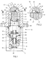
- the hydraulic valve shown in the figures is a Handbrake valve with a housing 10, which is essentially composed of a lower housing part 11 and an upper housing part 12.
- a valve bore 13 of the lower housing part 11 takes slidably on a control piston 14, is at one end closed a plug 15 and opens at the other End into a larger one formed within the two housing parts, Cross-sectionally cylindrical cavity 16.
- three Radial bores 17, 18 and 19 the radial bore 17th with a pressure medium source, the radial bore 18, the cavity 16 is closest, with a pressure medium reservoir and the radial bore 19 is to be connected to a consumer.
- the three holes are in addition to the reference numbers with the usual letter designations P, T and A marked.
- control piston 14 is a blind bore open to the plug 15 20 introduced, which via a plurality of radial control bores 21 with the circular cylindrical outer surface of the control piston 14 in Connection is established. Via the control holes 21, the blind hole 20 and the valve bore 13 can the consumer connection 19 of the Valve either with the pressure connection 17 or with the tank connection 18 are connected. The pressure in the consumer connection 19 acts on the control piston 14 in the axial direction and generates a force that the control piston 14 away from the plug 15 in seeks to insert the cavity 16.
- the second support element is a sleeve with a stepped axial bore 29 and is inside of the upper housing part 12 in the cavity 16 axially displaceable guided.
- the radial step between the two sections 30 and 31 of the axial bore 29 in the support element 28 is to the mouth the valve bore 13 directed into the cavity 16.
- the section 30 with the larger diameter is at this mouth open towards.
- the piston-like, first support element 27 is within the section 31 of the axial bore 29 in the support element 28 in the axial direction of the cavity 16 guided.
- control spring 26 clamped within the return spring 25 located in section 30 of the axial bore 29 of the second Support element 28 extends and there the first support element 27 acted upon.
- the shaft is in the region of the cavity 16 40 accessible from cavity 16.
- the Shaft sealed by a sealing ring 42 through a bearing eye of the upper housing part 12 to the outside, where a hand lever 43 is screwed into it.
- the swivel angle of the hand lever 43 limited.
- This recess is from the Been milled for 40.
- An axial blind bore 47 is introduced from one end face the bore wall in the area of the recess 46 in cross section only over an angle of less than 180 ° is present and only in the area of the recess as partly cylindrical groove is recognizable.
- a needle roller 48 is pressed. This is on the side of the recess 47 surrounded on its entire circumference by the material of the shaft 40 and thereby secured against falling out of the bore 47.
- the shaft 40 runs parallel to the blind bore 47 a further blind bore 49, which on the same end face of the Shaft 40 as the blind bore 47 is open and axially over the Recess 46 extends.
- the blind bore 49 is also inside the recess 46 can only be seen as a part-circular cylindrical groove.
- it is the through a further recess 50 Shaft 40, which is located in the center of the recess 46 and is shorter than this is completely interrupted and divided into two.
- each Part of the bore 49 is pressed in a needle roller 51 which axially protrudes into the recess 46, but the recess 50 leaves largely free.
- the two needle rollers 51 are the same. you Diameter is much larger than that of the needle roller 48. All needle rollers are located entirely within the outer circumference the shaft 40.
- the support elements Immerse 27 and 28 radially in the shaft 40.
- the support element 28 is by the return spring 25 with a flat, parallel to Axis of the shaft 40 extending stop surface 52 against the needle rollers 51 pressed. So that the support member 28 within the Pivot range of the hand lever 43 and the shaft 40 always on the Needle rollers 51 can rest, only the recess 46 is necessary.
- the clear distance between the needle rollers 51 and the recess 50 allow a deeper immersion of the support element 27 in the shaft 40 and the constant concern of this support element on the needle roller 48 with a stop surface 53.
- the needle rollers 48 and 51 are arranged so that the shaft 40th for the support elements 27 and 28 a two-armed lever in the Forms sense that the support elements 27 and 28 at a Rotation of the shaft 40 within the possible swivel range shift in opposite bends.
- the effective one Lever length for from the control spring 26 to the shaft 40 exerted force takes, starting from the end position according to Figure 2, when the shaft 40 rotates towards the other end position initially to a maximum value when the axis 41 of the Shaft 40 and plane spanned by the axis of the needle roller 48 is perpendicular to the direction of force, and then remove again.
- the ratio of the effective lever arm length for the return spring 25 to the effective lever arm length for the Control spring 26 in the end position of Figure 2 much larger than in the end position according to FIG. 1.
- the hand lever 43 is not shown in, but from the state of the art known as a tube, in which a locking pin is axially displaceable. In the in Figure 1 position shown, this locking pin by a spring pushed into a blind bore of the upper housing part 12 become. The position of the valve shown in FIG. 1 is therefore lockable. By pulling an axially adjustable on the hand lever 43 additional control element, the locking pin from the Blind hole are pulled out, so that a rotation of the shaft 40 and the hand lever 43 from the position shown in Figure 1 in the position shown in Figure 2 is possible. This panning can be brought about by the return spring 25 alone become. Starting from the position shown in FIG.
- the support element 28 initially with great force the needle rollers 51 and thus exerts a torque on the shaft 40 that is larger than that caused by the control spring 26 Counter moment.
- the shaft 40 rotates, as seen in FIG. 1, clockwise.
- the return spring 25 relaxes partially so that the force it exerts becomes less. Indeed the leverage ratio is gradually becoming more favorable for them.
- the force translated by the leverage ratio is sufficient to finally, the control spring 26 in its most biased Bring state in which by the control spring 26 generated spring force by the pressure in the consumer connection 19 corresponds to the pressure force generated on the control piston 14.
- the cavity 16 is through a small bore 60 in the lower housing part 11 connected to the tank connection 18 of the valve. Furthermore leads through the support element 27 through an axial bore 61.
- the cavity 16 is on both sides of the support elements 27 and 28 filled with oil, 60 changes in volume through the bore, which is characterized by more or less immersion of the control piston 14 result in the cavity 16, balanced can be.
- the oil also causes needle rollers 48 and 51 and the stop surfaces 52 and 53 on the support elements 27 and 28 wetted so that the friction between the touching Space is kept to a minimum. This also helps that the operating forces are low.
Landscapes
- Engineering & Computer Science (AREA)
- Transportation (AREA)
- Mechanical Engineering (AREA)
- Mechanically-Actuated Valves (AREA)
Description
Ein Hebel ist ein Bauteil, das um eine Achse verschwenkbar ist. Im Prinzip können die Federn direkt an dem Hebel anliegen, wobei dieser Hebel zugleich ein einziges die Abstützmittel bildendes Abstützelement für beide Federn sein würde. Die Federn sind jedoch besser geführt und in ihrem Spannungszustand genauer definiert, wenn gemäß Anspruch 3 die Abstützmittel für die Steuerungsfeder ein erstes Abstützelement und für die Rückstellfeder ein davon verschiedenes, zweites Abstützelement aufweisen und beide Abstützelemente linear verschiebbar sind. Bevorzugt sind die beiden Abstützelemente dabei parallel zueinander verschiebbar.
- Figur 1
- das Ausführungsbeispiel in der Bremsstellung und in einem durch die Achse des Regelkolbens gehenden Schnitt,
- Figur 2
- einen Schnitt in der gleichen Schnittebene wie in Figur 1, wobei sich jedoch das Ventil in der Fahrstellung befindet,
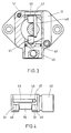
- Figur 3
- einen Schnitt entlang der Linie III-III aus Figur 1 und
- Figur 4
- eine Seitenansicht der Betätigungswelle des Ventils.
Claims (21)
- Hydraulisches Ventil, insbesondere zum Lüften einer Federspeicherbremse, mit einem Gehäuse (10) und einem daran gelagerten, in entgegengesetzte Richtungen verstellbaren Betätigungsorgan (43), mit einem im Gehäuse (10) bewegbar untergebrachten Ventilglied (14), mit einer Steuerungsfeder (26), die zwischen bewegbaren Abstützmitteln (27, 28) und dem Ventilglied (14) angeordnet ist, und mit einer Rückstellfeder (25), die zwischen dem Gehäuse (10) und den Abstützmitteln (27, 28) angeordnet ist, deren Spannung durch ein Bewegen des Betätigungsorgans (43) in die eine Richtung vergrößerbar ist unter gleichzeitiger Entspannung der Steuerungsfeder (26) und von welcher Rückstellfeder (25) bei in die entgegengesetzte Richtung frei bewegbarem Betätigungsorgan (43) die Abstützmittel (27, 28) im Sinne einer Spannungserhöhung der Steuerungsfeder (26) verstellbar sind, gekennzeichnet durch im Kraftfluß zwischen der Rückstellfeder (25) und der Steuerungsfeder (26) liegende Mittel (40, 48, 51) zur mechanischen Kraftverstärkung.
- Hydraulisches Ventil nach Anspruch 1 gekennzeichnet durch einen im Kraftfluß zwischen der Rückstellfeder (25) und der Steuerungsfeder (26) angeordneten Hebel (40, 48, 51).
- Hydraulisches Ventil nach Anspruch 2, dadurch gekennzeichnet, daß die Abstützmittel für die Steuerungsfeder (26) ein erstes Abstützelement (27) und für die Rückstellfeder (25) ein davon verschiedenes, zweites Abstützelement (28) aufweisen und daß beide Abstützelemente (27, 28) vorzugsweise parallel zueinander linear verschiebbar sind.
- Hydraulisches Ventil nach Anspruch 3, dadurch gekennzeichnet, daß das Verhältnis zwischen der wirksamen Länge des von der Rückstellfeder (25) beaufschlagten Hebelarms und der wirksamen Länge des von der Steuerungsfeder (26) beaufschlagten Hebelarms des Hebels (40, 48, 51) bei am weitesten entspannter Rückstellfeder (25) größer ist als bei am stärksten gespannter Rückstellfeder (25).
- Hydraulisches Ventil nach Anspruch 3 oder 4, dadurch gekennzeichnet, daß die Rückstellfeder (25) den Hebel (40, 48, 51) auf der einen Seite und die steuerungsfeder (26) den Hebel (40, 48, 51) auf der anderen Seite einer von der Bewegungsrichtung der Abstützelemente (27, 28) und der Achse (41) des Hebels (40, 48, 51) aufgespannten Ebene aus derselben Richtung beaufschlagen und die beiden Abstützelemente (27, 28) bei einer Verstellung entgegengesetzt zueinander verschiebbar sind.
- Hydraulisches Ventil nach Anspruch 5, dadurch gekennzeichnet, daß das zweite Abstützelement (28) im Gehäuse (10) und das erste Abstützelement (27) im zweiten Abstützelement (28) verschiebbar geführt ist und daß die Rückstellfeder (25) die Steuerungsfeder (26) umgibt.
- Hydraulisches Ventil nach Anspruch 5 oder 6, dadurch gekennzeichnet, daß das zweite Abstützelement (28) im Gehäuse (10) und daß erste Abstützelement (27) im zweiten Abstützelement (28) verschiebbar geführt ist, und daß sich die am Hebel (40, 48, 51) anliegende Anschlagfläche (53) des ersten Abstützelements (27) in jeder betrieblichen Position der beiden Abstützelemente (27, 28) näher an der Achse (41) des Hebels (40, 48, 51) befindet als die am Hebel (40, 48, 51) anliegende Anschlagfläche (52) des zweiten Abstützelements.
- Hydraulisches Ventil nach den Ansprüchen 4 und 7, dadurch gekennzeichnet, daß bei einer Bewegung des Hebels (40, 48, 51) von am stärksten gespannten in den am geringsten gespannten Zustand der Rückstellfeder (25) die wirksame Länge des von der Rückstellfeder (25) beaufschlagten Hebelarms kontinuierlich größer wird und im geringsten gespannten Zustand der Rückstellfeder (25) den maximal möglichen Betrag hat.
- Hydraulisches Ventil nach Anspruch 8, dadurch gekennzeichnet, daß bei einer Bewegung des Hebels (40, 48, 51) vom am stärksten gespannten in den am geringsten gespannten Zustand der Rückstellfeder (25) die wirksame Länge des von der Steuerungsfeder (26) beaufschlagten Hebelarms zunächst kontinuierlich größer wird, einen maximal möglichen Betrg annimmt und dann kontinuierlich kleiner wird.
- Hydraulisches Ventil nach einem der Ansprüche 3 bis 9, dadurch gekennzeichnet, daß der Hebel (40, 48, 51) eine im Gehäuse (10) gelagerte Welle (40) aufweist, daß sich die Anschlagstelle (48, 51) am Hebel (40, 48, 51) für wenigstens eines der Abstützelemente (27, 28) in einer betrieblichen Position des Hebels (40, 48, 51) innerhalb des Außendurchmessers der Welle (40) befindet und daß die Welle (40) zum Eintauchen wenigstens eines der beiden Abstützelemente (27, 28) mit einer Ausnehmung (46, 50) versehen ist.
- Hydraulisches Ventil nach Anspruch 10, dadurch gekennzeichnet, daß eine vom einen Abstützelement (28) beaufschlagte Kontur (51) der Welle (40) nur im Bereich dieses Abstützelements (28) vorhanden ist und daß das andere Abstützelement (27) in einer betrieblichen Position in einen in Richtung der Achse des Hebels (40, 48, 51) der Kontur (51) folgenden Freiraum (50) der Welle (40) eintaucht.
- Hydraulisches Ventil nach Anspruch 11, dadurch gekennzeichnet, daß die Kontur (51) beidseits des Freiraums (50) vorhanden und beidseits des Freiraums (50) von dem einen Abstützelement (28) beaufschlagt ist.
- Hydraulisches Ventil nach einem der Ansprüche 3 bis 12, dadurch gekennzeichnet, daß der Hebel (40, 48, 51) eine im Gehäuse (10) gelagerte Welle (40) aufweist und daß in der Welle (40) Stifte (48, 51) befestigt sind, die in die Ausnehmung (46, 50) der Welle (40) hineinragen und die von den Abstützelementen (27, 28) beaufschlagten Konturen der Welle (40) bilden.
- Hydraulisches Ventil nach Anspruch 13, dadurch gekennzeichnet, daß die Welle (40) für einen Stift (48, 51) eine axial verlaufende Bohrung (47, 49) aufweist, die axial aufgeschnitten ist, und daß der Stift (48, 51) auf seiner gesamten Länge durch noch vorhandene Bohrungswand gegen die von einer Feder (25, 26) auf ihn ausgeübte Kraft abgestützt ist.
- Hydraulisches Ventil nach Anspruch 14, dadurch gekennzeichnet, daß die Bohrung (47, 49) nur über einen Teil ihrer Länge aufgeschnitten ist.
- Hydraulisches Ventil nach Anspruch 14 oder 15, dadurch gekennzeichnet, daß der im aufgeschnittenen Teil der Bohrung (47, 49) noch vorhandene Kreisbogen der Bohrungswand kleiner oder gleich 180° ist.
- Hydraulisches Ventil nach einem der Ansprüche 13 bis 16, dadurch gekennzeichnet, daß in der Welle (40) zur Beaufschlagung durch das erste Abstützelement (27) ein erster Stift (48) und zur Beaufschlagung durch das zweite Abstützelement (28) ein zweiter Stift (51) befestigt ist und daß die Stifte (48, 51) unterschiedliche Durchmesser haben.
- Hydraulisches Ventil nach einem der Ansprüche 13 bis 17, dadurch gekennzeichnet, daß Nadelrollen (48, 51) die Stifte bilden.
- Hydraulisches Ventil nach einem der Ansprüche 2 bis 18, dadurch gekennzeichnet, daß das Betätigungsorgan (43) als ein schwenkbarer Hebel ausgebildet und an einer im Gehäuse (10) gelagerten Welle (40) befestigt ist und daß diese Welle (40) auch die Welle des zwischen den Federn (25, 26) angeordneten Hebels (40, 48, 51) ist.
- Hydraulisches Ventil nach einem der Ansprüche 3 bis 19, dadurch gekennzeichnet, daß ein mit einem Druckmittelvorratsbehälter zu verbindender Tankanschluß (18) vorhanden ist, daß ein Hohlraum (16) des Gehäuses (10), in dem sich die Rückstellfeder (25), die Steuerungsfeder (26), die Abstützelemente (27, 28) und die Mittel (40, 48, 51) zur Kraftverstärkung befinden, vorzugsweise intern mit dem Tankanschluß verbunden ist und daß durch einen Kanal (61) Öl zwischen den zwei Teilräumen beidseits der Abstützelemente (27, 28) austauschbar ist.
- Hydraulisches Ventil nach Anspruch 20, dadurch gekennzeichnet, daß sich der Kanal (61) in einem Abstützelement (27) befindet.
Applications Claiming Priority (3)
| Application Number | Priority Date | Filing Date | Title |
|---|---|---|---|
| DE4420136 | 1994-06-09 | ||
| DE4420136A DE4420136A1 (de) | 1994-06-09 | 1994-06-09 | Hydraulisches Ventil, insbesondere zum Lüften einer Federspeicherbremse |
| PCT/EP1995/001984 WO1995033639A1 (de) | 1994-06-09 | 1995-05-26 | Hydraulisches ventil, insbesondere zum lüften einer federspeicherbremse |
Publications (2)
| Publication Number | Publication Date |
|---|---|
| EP0764100A1 EP0764100A1 (de) | 1997-03-26 |
| EP0764100B1 true EP0764100B1 (de) | 1999-05-06 |
Family
ID=6520158
Family Applications (1)
| Application Number | Title | Priority Date | Filing Date |
|---|---|---|---|
| EP95922480A Expired - Lifetime EP0764100B1 (de) | 1994-06-09 | 1995-05-26 | Hydraulisches ventil, insbesondere zum lüften einer federspeicherbremse |
Country Status (3)
| Country | Link |
|---|---|
| EP (1) | EP0764100B1 (de) |
| DE (2) | DE4420136A1 (de) |
| WO (1) | WO1995033639A1 (de) |
Families Citing this family (1)
| Publication number | Priority date | Publication date | Assignee | Title |
|---|---|---|---|---|
| DE102012006874B4 (de) | 2012-04-04 | 2017-03-30 | Chr. Mayr Gmbh + Co. Kg | Abnehmbares druckmittelbetätigtes Handlüftsystem für Federdruckbremsen |
Family Cites Families (11)
| Publication number | Priority date | Publication date | Assignee | Title |
|---|---|---|---|---|
| GB812424A (en) * | 1956-02-08 | 1959-04-22 | Dewandre Co Ltd C | Improvements in or relating to control valves for fluid-pressure brake-operating mechanisms |
| US3355223A (en) * | 1966-07-28 | 1967-11-28 | Berg Mfg & Sales Co | Dual application valve |
| US3529630A (en) * | 1968-04-11 | 1970-09-22 | Westinghouse Electric Corp | Combined stop and control valve |
| DE1950816B2 (de) * | 1969-10-09 | 1976-08-12 | Applied Power Industries, Inc., Milwaukee, Wis. (V.St.A.) | Ventilvorrichtung fuer eine mit hilfskraft arbeitende hydraulische bremsanlage, insbesondere fahrzeug- bremsanlage |
| GB1450099A (en) * | 1973-04-20 | 1976-09-22 | Tokico Ltd | Actuating force generating devices |
| DE2519216C3 (de) * | 1975-04-30 | 1982-01-28 | Festo-Maschinenfabrik Gottlieb Stoll, 7300 Esslingen | Betätigungsvorrichtung für einen Schalter, insbesondere für einen pneumatischen Endschalter |
| US4076329A (en) * | 1977-01-12 | 1978-02-28 | Caterpillar Tractor Co. | Brake modulation valve for pedal-applied brakes |
| GB1586313A (en) * | 1978-05-30 | 1981-03-18 | Sabco Ltd | Mop wringers |
| DD205727A1 (de) * | 1982-07-13 | 1984-01-04 | Orsta Hydraulik Veb K | Verbundgesteuertes bremsventil |
| DE3301744A1 (de) * | 1983-01-20 | 1984-07-26 | Robert Bosch Gmbh, 7000 Stuttgart | Handbetaetigtes feststellbremsaggregat |
| DE3436130A1 (de) * | 1984-10-02 | 1986-04-10 | Mannesmann Rexroth GmbH, 8770 Lohr | Feststellbremsventil fuer hydraulische fremdkraftbremsanlagen |
-
1994
- 1994-06-09 DE DE4420136A patent/DE4420136A1/de not_active Withdrawn
-
1995
- 1995-05-26 EP EP95922480A patent/EP0764100B1/de not_active Expired - Lifetime
- 1995-05-26 DE DE59505851T patent/DE59505851D1/de not_active Expired - Fee Related
- 1995-05-26 WO PCT/EP1995/001984 patent/WO1995033639A1/de not_active Ceased
Also Published As
| Publication number | Publication date |
|---|---|
| DE4420136A1 (de) | 1995-12-14 |
| EP0764100A1 (de) | 1997-03-26 |
| DE59505851D1 (de) | 1999-06-10 |
| WO1995033639A1 (de) | 1995-12-14 |
Similar Documents
| Publication | Publication Date | Title |
|---|---|---|
| DE3345264A1 (de) | Drehmomenten-regeleinrichtung fuer eine verstellbare hydropumpe | |
| DE3609707A1 (de) | Hydraulische bremsanlage mit antiblockiersystem mit einer vorrichtung zur verbesserung der geradeauslaufstabilitaet eines fahrzeugs | |
| EP2582995A1 (de) | Scheibenbremse in hydraulischer selbstverstärkender bauart mit parkbremseinrichtung | |
| DE3821700C2 (de) | ||
| DE2064645B2 (de) | Vorrichtung zur regelung der brennstoffmenge einer brennkraftmaschine ueber eine servovorrichtung | |
| DE2843592C3 (de) | Hilfskraftlenkgetriebe | |
| DE3040321C2 (de) | Inchventil für einen hydrostatischen Fahrantrieb | |
| DE2349620C2 (de) | Fernsteuersystem für eine hydraulische Leistungsübertragungsvorrichtung | |
| DE10203384A1 (de) | Servolenksystem | |
| DE2335529C3 (de) | Hydraulischer Bremskraftverstärker | |
| DE832226C (de) | Dreiwegeschiebersteuerung fuer druckfluessigkeitsbetaetigte Vorrichtungen, insbesondere Bremszylinder | |
| DE1650575C3 (de) | Hydraulische Servolenkung für Kraftfahrzeuge | |
| DE3310747C2 (de) | ||
| DE3001608C2 (de) | Hydraulische Verstärkungseinrichtung | |
| DE4420136A1 (de) | Hydraulisches Ventil, insbesondere zum Lüften einer Federspeicherbremse | |
| DE2155409A1 (de) | Hydraulischer Kraftverstärker | |
| DE2508268C3 (de) | Steuerkolben fur hydraulische Druckmittelfolgesteuerungen, insbesondere für ein Lenkventil einer Servolenkeinrichtung von Fahrzeugen | |
| DE3545065A1 (de) | Steuereinrichtung fuer ein kraftfahrzeug | |
| EP1791737B1 (de) | Bremsanlage für kraftfahrzeuge | |
| DE2433567A1 (de) | Bremsventil fuer zwei getrennt oder gleichzeitig zu betaetigende bremskreise | |
| EP0437717B1 (de) | Sitzventil | |
| WO2004020864A1 (de) | Bremszange | |
| DE1680069A1 (de) | Bremsanlagen fuer Traktoren | |
| EP0815361A1 (de) | Rohrbruchsicherungsventil | |
| DE2554627A1 (de) | Vorrichtung zum axialen begrenzen der rueckstellbewegung eines hydraulisch beaufschlagbaren verstellelements |
Legal Events
| Date | Code | Title | Description |
|---|---|---|---|
| PUAI | Public reference made under article 153(3) epc to a published international application that has entered the european phase |
Free format text: ORIGINAL CODE: 0009012 |
|
| 17P | Request for examination filed |
Effective date: 19961030 |
|
| AK | Designated contracting states |
Kind code of ref document: A1 Designated state(s): DE FR GB IT SE |
|
| 17Q | First examination report despatched |
Effective date: 19971104 |
|
| RAP1 | Party data changed (applicant data changed or rights of an application transferred) |
Owner name: MANNESMANN REXROTH AG |
|
| GRAG | Despatch of communication of intention to grant |
Free format text: ORIGINAL CODE: EPIDOS AGRA |
|
| GRAG | Despatch of communication of intention to grant |
Free format text: ORIGINAL CODE: EPIDOS AGRA |
|
| GRAH | Despatch of communication of intention to grant a patent |
Free format text: ORIGINAL CODE: EPIDOS IGRA |
|
| GRAH | Despatch of communication of intention to grant a patent |
Free format text: ORIGINAL CODE: EPIDOS IGRA |
|
| GRAA | (expected) grant |
Free format text: ORIGINAL CODE: 0009210 |
|
| AK | Designated contracting states |
Kind code of ref document: B1 Designated state(s): DE FR GB IT SE |
|
| PG25 | Lapsed in a contracting state [announced via postgrant information from national office to epo] |
Ref country code: SE Free format text: THE PATENT HAS BEEN ANNULLED BY A DECISION OF A NATIONAL AUTHORITY Effective date: 19990506 Ref country code: IT Free format text: LAPSE BECAUSE OF FAILURE TO SUBMIT A TRANSLATION OF THE DESCRIPTION OR TO PAY THE FEE WITHIN THE PRE;WARNING: LAPSES OF ITALIAN PATENTS WITH EFFECTIVE DATE BEFORE 2007 MAY HAVE OCCURRED AT ANY TIME BEFORE 2007. THE CORRECT EFFECTIVE DATE MAY BE DIFFERENT FROM THE ONE RECORDED.SCRIBED TIME-LIMIT Effective date: 19990506 Ref country code: GB Free format text: LAPSE BECAUSE OF FAILURE TO SUBMIT A TRANSLATION OF THE DESCRIPTION OR TO PAY THE FEE WITHIN THE PRESCRIBED TIME-LIMIT Effective date: 19990506 Ref country code: FR Free format text: LAPSE BECAUSE OF FAILURE TO SUBMIT A TRANSLATION OF THE DESCRIPTION OR TO PAY THE FEE WITHIN THE PRESCRIBED TIME-LIMIT Effective date: 19990506 |
|
| REF | Corresponds to: |
Ref document number: 59505851 Country of ref document: DE Date of ref document: 19990610 |
|
| EN | Fr: translation not filed | ||
| GBV | Gb: ep patent (uk) treated as always having been void in accordance with gb section 77(7)/1977 [no translation filed] |
Effective date: 19990506 |
|
| PLBE | No opposition filed within time limit |
Free format text: ORIGINAL CODE: 0009261 |
|
| STAA | Information on the status of an ep patent application or granted ep patent |
Free format text: STATUS: NO OPPOSITION FILED WITHIN TIME LIMIT |
|
| 26N | No opposition filed | ||
| PGFP | Annual fee paid to national office [announced via postgrant information from national office to epo] |
Ref country code: DE Payment date: 20010625 Year of fee payment: 7 |
|
| PG25 | Lapsed in a contracting state [announced via postgrant information from national office to epo] |
Ref country code: DE Free format text: LAPSE BECAUSE OF NON-PAYMENT OF DUE FEES Effective date: 20021203 |