EP0764101B1 - Installation de transport suspendue - Google Patents
Installation de transport suspendue Download PDFInfo
- Publication number
- EP0764101B1 EP0764101B1 EP95924238A EP95924238A EP0764101B1 EP 0764101 B1 EP0764101 B1 EP 0764101B1 EP 95924238 A EP95924238 A EP 95924238A EP 95924238 A EP95924238 A EP 95924238A EP 0764101 B1 EP0764101 B1 EP 0764101B1
- Authority
- EP
- European Patent Office
- Prior art keywords
- driver
- drive chain
- drive
- elements
- suspension conveyor
- Prior art date
- Legal status (The legal status is an assumption and is not a legal conclusion. Google has not performed a legal analysis and makes no representation as to the accuracy of the status listed.)
- Expired - Lifetime
Links
- 238000009434 installation Methods 0.000 title claims abstract description 27
- 239000000725 suspension Substances 0.000 title claims abstract description 19
- 230000008878 coupling Effects 0.000 claims description 12
- 238000010168 coupling process Methods 0.000 claims description 12
- 238000005859 coupling reaction Methods 0.000 claims description 12
- 210000001331 nose Anatomy 0.000 description 9
- 230000003019 stabilising effect Effects 0.000 description 8
- 230000000630 rising effect Effects 0.000 description 4
- 238000010276 construction Methods 0.000 description 2
- 230000006835 compression Effects 0.000 description 1
- 238000007906 compression Methods 0.000 description 1
- 239000002184 metal Substances 0.000 description 1
- 238000000034 method Methods 0.000 description 1
- 229920003023 plastic Polymers 0.000 description 1
- 239000004033 plastic Substances 0.000 description 1
Images


Classifications
-
- B—PERFORMING OPERATIONS; TRANSPORTING
- B61—RAILWAYS
- B61B—RAILWAY SYSTEMS; EQUIPMENT THEREFOR NOT OTHERWISE PROVIDED FOR
- B61B10/00—Power and free systems
- B61B10/02—Power and free systems with suspended vehicles
- B61B10/025—Coupling and uncoupling means between power track abd vehicles
-
- B—PERFORMING OPERATIONS; TRANSPORTING
- B65—CONVEYING; PACKING; STORING; HANDLING THIN OR FILAMENTARY MATERIAL
- B65G—TRANSPORT OR STORAGE DEVICES, e.g. CONVEYORS FOR LOADING OR TIPPING, SHOP CONVEYOR SYSTEMS OR PNEUMATIC TUBE CONVEYORS
- B65G2201/00—Indexing codes relating to handling devices, e.g. conveyors, characterised by the type of product or load being conveyed or handled
- B65G2201/02—Articles
- B65G2201/0229—Clothes, clothes hangers
Definitions
- the invention relates to a suspension conveyor installation according to the precharacterizing part of claim 1.
- the suspension conveyor installation may in particular constitute an installation for sorting objects suspended from respective roller devices, e.g. for sorting coat hangers suspended from respective roller devices with each coat hanger carrying clothes.
- the objects are either conveyed or they are accumulated in stop paths.
- the driver elements have to be disengaged automatically from a roller device when the latter runs onto a stopped roller device or is to be stopped on its own.
- a trolley conveyor according to the precharacterizing part of claim 1 is known where a dog consisting of a longish, flat plate without any links can be coupled to and discoupled from a trolley.
- the dog is mounted shiftable to a conveyor chain.
- this relatively longish plate does not allow sharp curves of the conveyor chain.
- the invention solves the problem of providing a driver mechanism allowing the driver elements to automatically engage and release roller devices that are to be entrained, said driver mechanism permitting a guidance as flexible as possible while being adaptable to varying requirements in a modular manner.
- the driver element when the drive receiving element of a roller device is engaged in the driver recess of one of the driver elements, and thus entrained by the latter, the driver element will be urged upwards by a stopper arrangement or by a stopped roller device, in particular by the drive receiving element thereof, when the lifting ramp of the plate-shaped driver abuts onto an obstacle - such as said stopper arrangement or said drive receiving element of the stopped roller device - obstructing the path of the driver element, resulting in the driver recess, and thus the driver element, being released from the drive receiving element of the roller device previously entrained.
- the particular driver plate While passing the stopped roller devices and the stopper arrangement, the particular driver plate is then maintained in the disengaged position because the drive receiving elements of the stopped roller devices, or the stopper arrangement, glide on the glider surface of the driver element until the driver element has passed the stopping arrangement. Thereafter, the driver plate is returned to its engaging position by means of a return spring, or by its own weight, in order to automatically entrain the next roller device.
- the driver plate in this engaging position runs onto the drive receiving element of a roller device to be conveyed
- the driver plate is first elevated again to the disengaged position by the drive receiving element abutting onto the lifting ramp of the driver plate, until the drive receiving element is overtaken by the driver recess whereby the driver plate is returned to the engaged position, with the drive receiving element being received in the driver recess.
- an installation for conveying transport hooks suspended from a trolley conveyor is disclosed as such in DE-A-38 12 023, wherein a drive chain extends above the trolley conveyor and carries driver plates each comprising an oblique lifting ramp at the leading end of the plate, an adjoining glider surface, and an adjoining driver recess.
- the driver plates are firmly affixed to the drive chain; hence, measures have to be taken to allow the drive chain to escape upwards when the driver plate runs onto transport hooks waiting at a standstill. Therefore, such a conveyor installation cannot be used if the drive chain cannot give way, as in the type of suspension conveyor installation according to the invention.
- the prior art installation does not provide for roller devices comprising drive receiving elements for co-operation with the driver plates.
- the driver elements are designed as rigid plates, the leading ends of which are pivotably mounted to the drive chain.
- the driver element Each time the drive chain of this installation travels through a curve, the driver element has to swivel out of the curve, which requires considerable construction space; thus, the possible radius of curvature of the drive chain route cannot be chosen as small as desired.
- the driver elements are designed in the form of link plates mounted to the drive chain such as to be displaceable vertically upwards toward the drive chain, wherein the links of the link plates are pivotable with respect to each other about axes perpendicular to the drive chain, but can be displaced only collectively towards the drive chain.
- the driver plate is neither swivelled into the engaging position nor swivelled out of the engaging position, but will be moved out of the engaging position by straight vertical lifting, and moved into the engaging position by straight vertical lowering.
- the driver element can conform to any small radius of curvature, through which the drive chain passes, without swivelling out of the curved path.
- the particular drive receiving element may be arranged as a drive receiving reel formed on the top end of the roller device and rotatable about a horizontal axis. Arranging the drive receiving element in the form of a reel provides the advantage that only little friction is produced when the driver elements overtake the roller devices. Further, it is ensured that drive receiving elements in the form of reels can readily engage and release, respectively, the driver element, in particular the driver recess.
- the drive receiving element is designed as a drive receiving projection formed on the top end of the roller device.
- This embodiment provides the advantage that the driver element and the drive receiving element can be caused to firmly engage each other, allowing great conveying forces to be transferred from the drive chain to the roller devices through the driving and drive receiving elements.
- An advantageous development provides the features that, starting from the leading end of the driver element, the lifting ramp and the succeeding glider surface are followed by a pass ramp and finally by a driver hook, with the driver recess extending between the pass ramp and the driver hook.
- a second lifting ramp is advantageously disposed at a trailing end of the respective driver element behind the driver hook.
- a further glider surface - in addition to the first mentioned glider surface - may be arranged at the trailing rear end of the driver element behind the driver recess, in particular allowing to shorten the longitudinal dimension of the driver element.
- two respective roller devices are connected to each other by a lower connecting rod to form a tandem trolley.
- the connecting rod may be utilised as a transport rod for the goods to be conveyed, for example, clothes suspended from coat hangers.
- the drive receiving elements of both roller devices are advantageously each designed as a hook-like drive receiving projection oriented obliquely upwards and towards the centre of the tandem trolley. This permits such tandem trolleys to be entrained in both directions by an abovedescribed driver element.
- each of the two roller devices has only one set of coaxial stabilising rollers or only one stabilising roller. This is advantageous because in the tandem trolley design, a distance between the roller devices firmly interconnected through the connecting rod is ensured and, thus, one stabilising roller or one set of coaxial stabilising rollers, respectively, already provide sufficient tilting stability.
- the roller devices are connected to the connecting rod through coupling members adapted to engage corresponding coupling members of adjacent tandem trolleys in order to form a chain of tandem trolleys.
- the width of the drive receiving element is at least twice the width of the driver element.
- a plurality of driver elements can be guided in parallel, whereby for instance driver elements of three different paths branching from each other can be guided in parallel.
- Figure 1 is a schematic representation of a plan view of part of a rail system in which two loop circuits 1 are connected to a straight path 2.
- Switch blades 3 are arranged to be switched in order to divert roller devices 4 (likewise shown schematically) from said path 2 into the loops 1, or to return the roller devices 4 from said loops 1 onto the path 2.
- roller devices 4 likewise shown schematically
- two pairs of switch blades are provided, and the switch blades 3 of each pair extend substantially in parallel; it is also possible, however, to provide only one switch blade 3, for example, depending on the direction of travel and diversion of the roller devices 4.
- stoppers 24 are provided for stopping the roller devices 4 within the loops 1, causing the roller devices 4 to queue up, as will be explained below.
- the stoppers 24 may be arranged to be moved as obstacles into the path of travel of the roller devices 4 or retracted from said path in order to stop the roller devices 4 or to release them, respectively.
- switch blades 3 it is also possible for switch blades 3 to be replaced by mere junctions; in this event, the invention ensures that no clogging occurs if two driver elements arrive at a junction at the same time, as will be described in greater detail below.
- Figure 2 schematically illustrates the structure of the rails, with Figure 2a) showing a schematic perspective view of a rail portion which in this exemplary embodiment is composed of two path sections 5 screwed to one another through bridges 6.
- the rail comprises profiled support beams 7 and profiled travel beams 8 on which the carrying rollers 9 of roller devices 4 travel, as apparent from Figures 2b) and 2c).
- Figure 2c) is a sectional view taken along line A-B in Figure 2c)
- Figure 2c) is a side view of the rail with roller devices 4 travelling thereon.
- Stabilising rollers 10 engage a bottom travelling surface formed on the travel beams 8 to ensure smooth travelling of the roller devices 4, i.e. to prevent the roller devices 4 from rotating about a horizontal axis perpendicular to the direction of travel, which could impair the smooth running of the roller devices.
- lateral guiding rollers 12 running between the profiled travel beams 8 provide for lateral guidance of the roller devices 4.
- the top ends of the roller devices 4 are provided with respective drive receiving elements 11 which can be engaged by the driver elements; the latter are not shown in Figure 2c) but will be clearly illustrated and detailed in the subsequent drawing Figures.
- Figure 3 is a side view corresponding to that in Figure 2, illustrating another, particularly advantageous design of the drive receiving elements of the roller devices as well as an advantageous embodiment of the related driver element 13 in the form of a link plate.
- the driver element 13 On the left-hand side of Figure 3, the driver element 13 is shown in its engaged state, while it is shown in its disengaged state on the right-hand side of the Figure.
- the driver element 13 is comprised of individual links 14 articulated to each other.
- the driver element, or its individual links 14, are mounted to the drive chain 16 through chain pins 15 and are vertically displaceable.
- the drive chain 16 may be pulled in the direction of travel indicated by an arrow 17, for example.
- the individual links 14 of the link plate forming the driver element can be moved only collectively upwards or downwards to the engaged or disengaged positions, respectively.
- the driver element 13 is provided with an obliquely descending lifting ramp 18 for lifting the driver element 13 upon abutment, and with an adjoining glider surface 19, extending parallel to the drive chain 16, for keeping the driver element 13 in the lifted position.
- a driver recess 20 is arranged adjacent to the glider surface 19 and is confined, on the one hand, by a pass ramp 21 rising obliquely from the glider surface 19 and, on the other hand, by an inclined surface 22 of a driver nose 20a descending obliquely in the conveying direction.
- the trailing end of the driver element 13 is provided with a further pass ramp 23 rising obliquely, while a further short glider surface 25, extending along the driver nose 20a, for keeping the driver element 13 in the lifted position is arranged between said further pass ramp 23 and the inclined surface 22.
- the driver recess 20 engages the drive receiving element 11, which in this exemplary embodiment is formed as a drive receiving projection.
- the hook-shaped drive receiving projection 11 comprises a sloped surface rising obliquely towards the trailing end of the roller device, which sloped surface seats on, and is entrained by, the inclined surface 22 of the driver element 13 in the engaged position.
- the associated roller device 4 is automatically conveyed from the left-hand side to the right-hand side until the roller device 4 is stopped, for example, by a stopper 24 or another roller device 4 already at standstill.
- a roller device 4 approaching another roller device 4 already stopped is illustrated on the left-hand side of Figure 3.
- the lifting ramp 18 abuts onto the drive receiving element 11, i.e. in the present case onto a hook-shaped point of the drive receiving element 11 formed as a drive receiving projection 11.
- the driver element 13 is conveyed on by the drive chain 16
- the driver element 13 is pushed upwards until it finally reaches the disengaged position depicted on the right-hand side of Figure 3.
- the glider surface 19 and the further glider surface 25 cooperate to make the driver element 13 glide over the stopper 24, or another roller device 4 already stopped, while the driver element 13 is held in the disengaged position and further conveyed in the direction of the arrow.
- roller devices 4 automatically delivered by respective driver elements 13 are effectively lined up, with the driver elements 13 disengaging automatically from the drive receiving elements 11.
- the driver elements 13 are enabled to overtake, or pass, the roller devices 4.
- the pass ramps 21 and 23 also allow the driver elements 13 to be passed by the roller devices 4. This is necessary in particular when the drive chain 16 comes to a standstill while the roller devices 4 are nevertheless to be conveyed further by hand.
- the drive receiving projection 11 is likewise provided with a lifting ramp 26 on the leading end of the top face of the roller device 4, said lifting ramp 26 descending obliquely towards the front end.
- the glider surfaces 19 and 25 ride over the drive receiving elements 11, both when the driver elements 13 overtake the roller devices 4 and when the roller devices 4 overtake the driver elements 13.
- the glider surfaces 19 and 25 may ride over a gliding member 27 arranged for this purpose on each drive receiving element 11.
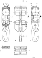
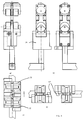
- roller devices 4 The structure of the roller devices 4 according to this embodiment can be seen in greater detail in Figure 4, wherein Figure 4a) is a sectional view taken along line C-D in Figure 4b), while Figure 4b) is a front view of the roller device 4, Figure 4c) is a side view of the roller device 4, Figure 4d) is a sectional view taken along line E-F in Figure 4c), and Figure 4e) is a plan view of the roller device 4.
- the carrying rollers 9, stabilising rollers 10 and lateral guiding rollers 12 are particularly well visible in Figure 4.
- the drive receiving element 11 formed as a drive receiving projection is clearly apparent; the drive receiving projection is provided, on the one hand, with a drive receiving nose 28 comprising an inclined surface 28a rising obliquely towards the trailing end of roller device 4 and, on the other hand, with the gliding member 27.
- the gliding member 27 may be constituted by a simple, round metal pin embedded in the plastics casing of roller device 4.
- roller device 4 When a roller device 4 is diverted - by a switch arranged at a branch point of the rail system - from one conveyor path to another conveyor path branching off the first one while being associated with a different drive chain, then the roller device can be disengaged automatically from the drive chain of the first conveyor path.
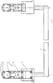
- Figure 5 shows a further development of the aforementioned embodiment in the form of a so-called tandem trolley combining two roller devices 4 through a connecting rod 29 and respective rotatable coupling rods.
- coupling members 30 are provided which link the roller devices 4 to the connecting rod 29 and are arranged to intercouple several tandem trolleys, as will be explained in greater detail with reference to Figure 6.
- a peculiarity of this embodiment is that only one set of stabilising rollers 10 coaxial to one another is required for each roller device 4; for the sake of a simple construction, the design of said set of stabilising rollers 10 may be identical to that of the set of carrying rollers 9 coaxial to one another.
- the noses 28 of the drive receiving elements 11 are inclined upwardly and towards the centre of the tandem trolley so that the noses 28 of both roller devices 4 oppose each other.
- the tandem trolley can thus be driven in both directions by respective driver elements 13 (cf. Figure 3).
- the connecting rod 29 serves to receive the load, for example, to receive coat hangers.
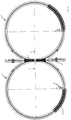
- Figure 6a) is a front view of a tandem trolley illustrated in the side view according to Figure 5, while Figure 6b) shows two roller devices 4 of two adjoining tandem trolleys, which roller devices 4 can be coupled to each other by means of the coupling members 30, as shown in the plan view according to Figure 6c).
- Figure 6d) is a plan view of the coupling members 30 in their disengaged position; this Figure in particular illustrates the coupling hooks 42 arranged to engage each other in order to take the coupled position depicted in Figure 6c). In this manner, a plurality of tandem trolleys can be coupled to each other to form a long chain.
- FIG 7a represents a side view of another embodiment.
- the driver element 36 is again formed as a link plate mounted to the drive chain 16 in a vertically displaceable fashion.
- the drive receiving element 11 is arranged as a rotatable drive receiving reel.
- the driver element 36 comprises an inclined pass ramp 38 allowing the driver elements 36 to be readily overtaken by the roller devices 4.
- an oblique lifting ramp 39 for lifting the driver element 13 upon abutment is disposed at the leading end of driver element 36.
- the trailing end of the link plate forming the driver plate is provided with an oblique pass ramp 31, owing to which the driver element 36 can be overtaken, or passed, by the roller devices 4 if the driver element 36 is at a standstill while the roller devices are pushed on by hand, on the analogy of the driver element 13 already described with reference to Figure 3.
- Figure 7b) is a partial bottom view and Figure 7c) is a partial plan view of the embodiment shown in Figure 7a); however, the roller devices are not illustrated in Figures 7b) and 7c), and only the drive chain 16 and one driver element 36 are shown.
- the individual links 32, 33 and 34 of the driver element 36 are supported in a pivotable and vertically displaceable manner by pins 35 fixed to the drive chain 16, and the links 33 and 34 are each provided with a curvature 40 such as to be readily pivotable with respect to each other.
- the number of links 33 may be chosen according to the desired length of the glider surface 41.
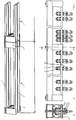
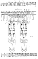
- Figures 8a) and 8b) represent sectional views corresponding to the sectional view shown in Figure 2b), wherein a front view of the driver element 36 - depicted in Figure 7a), for example - and a front view of a roller device 4 are illustrated.
- the drive receiving element 11 is substantially wider than the driver element 36, thus enabling e.g. three driver elements 36 to be guided in parallel simultaneously, as shown in Figure 8b).
- driver elements from three different paths branching from each other may be guided on a path section as that designated G-H in Figure 1, for example.
- the driver elements are provided with lateral lifting ramps 43 to the left and to the right. Owing to this design feature, driver elements arriving from different paths may get out of each other's way in the intersection areas.
- Figures 8a) and 8b) show compression coil springs 44 biasing the driver elements downwardly to ensure a reliable operation.
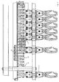
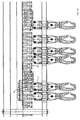
- the driver elements 13 are arranged at intervals on the drive chain 16, said intervals being determined by the thickness of the conveyed articles as measured in the conveying direction.
- a roller device is diverted at a branch point of the rail system, e.g. at branch point G-H in Figure 1, from one conveyor path to another conveyor path each associated with a different drive chain 16, requiring the roller device to be transferred from the first drive chain to the other one, then the presence of the intervals between the driver elements 13 may result in that the respective driver element 13 of the second drive chain has not yet arrived at the branch point when the roller device to be diverted has already been released from the first drive chain.
- the embodiment according to Figures 9 and 10 is preferably provided.
- additional driver blocks 50 are fixed to the drive chain 16 between the driver elements 13 and are supported by the chain pins 51 projecting from one side of drive chain 16.
- the bottom surfaces of the driver blocks 50 are arranged at a distance above the bottom surfaces of the driver elements 13 in the lowered position of the driver elements 13; thus, the bottom surfaces of the driver blocks 50 are normally arranged at a distance above the top surfaces of the roller devices 4 as well.
- the driver blocks 50 will also be lowered by said distance so that the roller devices 4 can be also entrained by driver blocks 50 cooperating with the top surface of the roller devices.
- the driver blocks are designed to yield resiliently such as to be somewhat compressed resiliently when they engage the top side of the roller devices substantially by friction.
Landscapes
- Engineering & Computer Science (AREA)
- Transportation (AREA)
- Mechanical Engineering (AREA)
- Chain Conveyers (AREA)
- Control Of Conveyors (AREA)
- Attitude Control For Articles On Conveyors (AREA)
- Pusher Or Impeller Conveyors (AREA)
- Vehicle Body Suspensions (AREA)
- Structure Of Belt Conveyors (AREA)
- Escalators And Moving Walkways (AREA)
Claims (11)
- Installation de convoyeur en suspension comprenant des dispositifs de roulement (4) déplaçables sur des rails d'un système de rails, et une chaíne d'entraínement (16) qui se déplace le long dudit système de rails au-dessus des rails (8), la face inférieure de la chaíne d'entraínement (16) comportant des éléments d'entraínement (13,36) destinés à engrener avec des éléments respectifs de réception d'entraínement (11) disposés sur les faces supérieures des dispositifs de roulement (4), dans lequel, dans une position engagée, un élément d'entraínement (13,36) engrène avec un élément respectif de réception d'entraínement (11), tout en étant dégagé de l'élément de réception d'entraínement (11), dans une position dégagée,
la longueur des éléments d'entraínement (13,36), mesurée dans la direction de convoyage, dépassant la dimension des dispositifs de roulement (4) telle qu'elle est mesurée dans la direction de convoyage,
le bord inférieur de chaque élément d'entraínement (13,36) comprenant une rampe oblique de soulèvement (18,39), disposée au niveau de l'extrémité avant de l'élément d'entraínement (13,36) et descendant en sens opposé de la direction de convoyage, pour soulever l'élément d'entraínement (13,36) lors de sa venue en position d'aboutement; et une surface de glissement (19,25,41) qui est adjacente à la rampe de soulèvement (18,39) et s'étend dans la direction de convoyage, pour maintenir l'élément d'entraínement (13,36) à l'état soulevé;
de telle sorte que la position dégagée est établie ou maintenue respectivement par la rampe de soulèvement (18,39) venant en butée contre un obstacle ou un dispositif de roulement adjacent (4), et par la surface de glissement (19,25,41), qui glisse sur ledit obstacle ou sur l'extrémité supérieure d'un dispositif de roulement adjacent (4);
caractérisée en ce queles éléments d'entraínement (13,36) sont agencés en tant que plaques d'entraínement sous la forme de plaques articulées montées sur la chaíne d'entraínement (16) de manière à être déplaçables collectivement selon un mouvement ascendant vertical en direction de la chaíne d'entraínement (16), les articulations (14) des plaques articulées pouvant pivoter les unes par rapport aux autres autour d'axes verticaux perpendiculaires à la chaíne d'entraínement (16); etle bord inférieur de chaque élément d'entraínement (13,36) comprend en outre un renfoncement d'entraínement (20,37), qui est adjacent à la surface de glissement (19,25,31), pour recevoir l'élément de réception d'entraínement (11) d'un dispositif de roulement respectif (4). - Installation de convoyeur en suspension selon la revendication 1, caractérisée en ce que l'élément de réception d'entraínement (11) est agencé sous la forme d'une partie saillante de réception d'entraínement qui fait saillie vers le haut à partir de l'extrémité supérieure du dispositif de roulement associé.
- Installation de convoyeur en suspension selon la revendication 2, caractérisée en ce qu'une tige coulissante (27), qui s'étend transversalement par rapport à la direction de convoyage, est insérée au niveau du sommet supérieur de la partie saillante de réception d'entraínement (11), de manière à coopérer avec les surfaces de glissement (19,25,41) des éléments d'entraínement (13).
- Installation de convoyeur en suspension selon la revendication 2 ou 3, caractérisée en ce qu'à partir de l'extrémité avant de l'élément d'entraínement respectif (13), la rampe de soulèvement (18) et la surface de glissement adjacente (19) sont suivies par une rampe oblique de passage (21) qui descend dans la direction de convoyage, et sont en outre suivies par une partie saillante d'entraínement (28) en forme de crochet, un renfoncement d'entraínement (20) s'étendant entre la rampe de passage (21) et la partie saillante d'entraínement (28).
- Installation de convoyeur en suspension selon l'une quelconque des revendications 1 à 4, caractérisé en ce qu'une seconde rampe de soulèvement (23), qui descend obliquement dans la direction de convoyage, pour soulever le crochet en aboutement, est disposée au niveau d'une extrémité arrière de l'élément d'entraínement respectif (13) en arrière du crochet d'entraínement.
- Installation de convoyeur en suspension selon l'une quelconque des revendications 1 à 5, caractérisée en ce que des rampes latérales de soulèvement (43), pour soulever l'élément d'entraínement (13,36) lorsqu'il vient en butée, sont prévues de manière à s'étendre le long de bords latéraux inférieurs de l'élément d'entraínement respectif (13, 36).
- Installation de convoyeur en suspension selon l'une quelconque des revendications 1 à 6, caractérisée en ce que deux dispositifs de roulement respectifs (4) sont raccordés entre eux par une tige inférieure de liaison (29) pour former un chariot tandem, et que les éléments de réception d'entraínement (11) des deux dispositifs de roulement (4) sont agencés chacun sous la forme d'une partie saillante de réception d'entraínement en forme de crochet (11) tournée obliquement vers le centre du chariot tandem.
- Installation de convoyeur en suspension selon la revendication 7, caractérisée en ce que les dispositifs de roulement (4) sont raccordés à la tige de raccordement (29) par des éléments d'accouplement (30) aptes à engrener avec des éléments d'accouplement correspondants (30) de chariots tandem adjacents pour former une chaíne de chariots tandem.
- Installation de convoyeur en suspension selon l'une quelconque des revendications précédentes, caractérisée en ce que la largeur de l'élément de réception d'entraínement (11), mesurée perpendiculairement à la direction de convoyage et à la chaíne d'entraínement (16), est égale au moins au double de la largeur de l'élément de réception d'entraínement (11), mesuré perpendiculairement à la direction de convoyage et à la chaíne d'entraínement (16), est égale au moins au double de la largeur de l'élément d'entraínement (13,36).
- Installation de convoyeur en suspension selon l'une quelconque des revendications 1 à 9, caractérisée en ce que des blocs d'entraínement (50) sont fixés à la chaíne d'entraínement (16) entre les éléments d'entraínement espacés (13); que les surfaces inférieures des blocs d'entraínement (50) sont disposées à une certaine distance au-dessus des surfaces inférieures des éléments d'entraínement (13) lorsque les éléments d'entraínement (13) sont dans la position engagée; et que dans les zones de commutateurs (3), la chaíne d'entraínement (16) circule à un niveau abaissé à un degré tel que les surfaces inférieures des blocs d'entraínement (50) sont légèrement plus basses que les extrémités supérieures des dispositifs de roulement (4), ce qui permet à un franchir un dispositif de roulement (4) dépassé par un bloc d'entraínement (50) d'être entraíné par ledit bloc d'entraínement (50).
- Installation de convoyeur en suspension selon la revendication 10, caractérisée en ce qu'au moins les extrémités inférieures des blocs d'entraínement (50) sont agencées de manière à fléchir élastiquement.
Applications Claiming Priority (3)
| Application Number | Priority Date | Filing Date | Title |
|---|---|---|---|
| DE9409663U DE9409663U1 (de) | 1994-06-15 | 1994-06-15 | Hängeförderanlage |
| DE9409663U | 1994-06-15 | ||
| PCT/EP1995/002312 WO1995034452A1 (fr) | 1994-06-15 | 1995-06-14 | Installation de transport suspendue |
Publications (2)
| Publication Number | Publication Date |
|---|---|
| EP0764101A1 EP0764101A1 (fr) | 1997-03-26 |
| EP0764101B1 true EP0764101B1 (fr) | 1998-09-23 |
Family
ID=6909871
Family Applications (1)
| Application Number | Title | Priority Date | Filing Date |
|---|---|---|---|
| EP95924238A Expired - Lifetime EP0764101B1 (fr) | 1994-06-15 | 1995-06-14 | Installation de transport suspendue |
Country Status (8)
| Country | Link |
|---|---|
| US (1) | US5819906A (fr) |
| EP (1) | EP0764101B1 (fr) |
| AT (1) | ATE171424T1 (fr) |
| AU (1) | AU2882995A (fr) |
| CA (1) | CA2185912A1 (fr) |
| DE (2) | DE9409663U1 (fr) |
| ES (1) | ES2123259T3 (fr) |
| WO (1) | WO1995034452A1 (fr) |
Families Citing this family (25)
| Publication number | Priority date | Publication date | Assignee | Title |
|---|---|---|---|---|
| US6464067B1 (en) * | 1997-12-23 | 2002-10-15 | Ferag Ag | Method and device for storing transport elements |
| DK1042203T3 (da) * | 1997-12-23 | 2003-03-31 | Ferag Ag | Transportsystem |
| DE19816688A1 (de) * | 1998-04-15 | 1999-10-28 | Wf Logistik Gmbh | Fördergutträger |
| US6688451B2 (en) * | 2000-04-05 | 2004-02-10 | Stephen J. Derby | Multi-head robot system and method of use |
| DE10031033A1 (de) * | 2000-06-26 | 2002-01-03 | Wf Logistik Gmbh | Fördereinrichtung, insbesondere Hängefördereinrichtung |
| US6588579B2 (en) | 2001-03-27 | 2003-07-08 | Jerry Taeger | Conveyor system accessories |
| DE20110857U1 (de) * | 2001-07-04 | 2002-02-07 | PEP Fördertechnik GmbH, 33609 Bielefeld | Schleppklinkenförderer |
| DE102005006455A1 (de) * | 2005-02-12 | 2006-08-24 | Dürkopp Adler AG | Transport-System für hängende Gegenstände |
| DE202005002903U1 (de) * | 2005-02-22 | 2005-09-29 | Krones Ag | Vorrichtung zum Zuführen von in Säcken angelieferten sterilen Verschlüssen in eine Abfüllanlage für Flaschen oder dgl. |
| DE102005057852B4 (de) * | 2005-12-03 | 2009-12-03 | Eisenmann Anlagenbau Gmbh & Co. Kg | Vorrichtung zur Förderung von Werkstücken |
| US7568575B2 (en) * | 2006-04-28 | 2009-08-04 | United Technologies Corporation | Engine support system |
| DE102010010107A1 (de) * | 2010-03-04 | 2011-09-08 | Dürkopp Fördertechnik GmbH | Förderanlage für hängende Gegenstände |
| US8777819B1 (en) * | 2010-06-15 | 2014-07-15 | Kelvin Quintana | Boxing training system |
| DE102010053426B3 (de) * | 2010-11-30 | 2012-06-06 | SSI Schäfer PEEM GmbH | Hängeförderer und Antriebskette für den Hängeförderer |
| US9228451B2 (en) | 2011-05-03 | 2016-01-05 | Pratt & Whitney Canada Corp. | Gas turbine engine module adapter to a carrier |
| DE102011119411B4 (de) * | 2011-11-21 | 2015-03-05 | SSI Schäfer PEEM GmbH | Stopper-Einheit für Klinkenförderer |
| DE102013100132A1 (de) * | 2013-01-08 | 2014-07-10 | Thomas Otto | Kettenglied einer Förderkette, Förderkette einer Fördervorrichtung und Fördervorrichtung |
| CH711921A1 (de) * | 2015-12-16 | 2017-06-30 | Ferag Ag | Laufrollengeführtes Förderorgan und Förderanlage mit derartigen Förderorganen. |
| CH712786A1 (de) * | 2016-08-02 | 2018-02-15 | Ferag Ag | Fördersystem zum Fördern von Fördergütern, mit einer Mitnehmerkette mit mindestens einem Mitnehmer zum Mitnehmen eines Förderwagens. |
| DE202017106670U1 (de) * | 2017-11-03 | 2019-02-05 | Dematic Logistics Gmbh | Kettenglied, Förderkette und Fördervorrichtung |
| CN109956265A (zh) * | 2017-12-14 | 2019-07-02 | 丹阳市延陵镇弘理木材厂 | 一种悬挂系统带传动提升机构 |
| DE102018201541B4 (de) * | 2018-02-01 | 2025-05-08 | Vanderlande Industries B.V. | Stauförderanlage |
| DE102019208476A1 (de) | 2019-06-11 | 2020-12-17 | BEUMER Group GmbH & Co. KG | Vereinzelungseinrichtung, Zugmittel mit zumindest einer Vereinzelungseinrichtung, Transportsystem und Verfahren zum Vereinzeln und Mitnehmen zumindest eines Ladungsträgers |
| AT523665A1 (de) * | 2020-03-30 | 2021-10-15 | Tgw Mechanics Gmbh | Transportträger, Hängefördervorrichtung und Verfahren zum Transport von Hängeware |
| CN117401378B (zh) * | 2023-12-14 | 2024-02-20 | 山东尚牛网络科技有限公司 | 一种服装生产智能吊挂系统 |
Family Cites Families (12)
| Publication number | Priority date | Publication date | Assignee | Title |
|---|---|---|---|---|
| US3242875A (en) * | 1962-01-05 | 1966-03-29 | King Ltd Geo W | Conveyor systems |
| GB980358A (en) * | 1963-01-05 | 1965-01-13 | King Ltd Geo W | Improvements in or relating to conveyor systems |
| US3389662A (en) * | 1964-10-23 | 1968-06-25 | Si Handling Systems | Low profile conveyor |
| CH482217A (fr) * | 1968-09-26 | 1969-11-30 | Paillard Sa | Télémètre à faisceau lumineux |
| FR2028057B1 (fr) * | 1969-01-17 | 1975-11-21 | Mabor Ste | |
| DE2634519C2 (de) * | 1976-07-31 | 1978-06-08 | J. Sandt Ag, 6780 Pirmasens | Schleppkreisförderer |
| US4287829A (en) * | 1977-10-05 | 1981-09-08 | Nakanishi Metal Works Co., Ltd. | Carrier stopping device for power-and-free conveyor |
| DE7804844U1 (de) * | 1978-02-18 | 1978-06-08 | Licentia Patent-Verwaltungs-Gmbh, 6000 Frankfurt | Foerderanlage mit einer transportkette und daran gehalterten mitnehmerelementen |
| GB2038743A (en) * | 1979-01-02 | 1980-07-30 | Goldschmidt S | Improvements in or relating to trolley conveyors |
| DE3405360C2 (de) * | 1984-02-15 | 1986-10-16 | Mannesmann AG, 4000 Düsseldorf | An einer Tragschiene verfahrbaren Förderwagen einer Schleppkettenförderanlage |
| DE3812023A1 (de) * | 1988-04-11 | 1989-10-26 | Riniker Ag | Foerdervorrichtung |
| DE9401948U1 (de) * | 1994-02-05 | 1994-04-07 | psb GmbH Förderanlagen und Lagertechnik, 66955 Pirmasens | Trolley für Hängeförderanlagen |
-
1994
- 1994-06-15 DE DE9409663U patent/DE9409663U1/de not_active Expired - Lifetime
-
1995
- 1995-06-14 AT AT95924238T patent/ATE171424T1/de not_active IP Right Cessation
- 1995-06-14 EP EP95924238A patent/EP0764101B1/fr not_active Expired - Lifetime
- 1995-06-14 DE DE69504972T patent/DE69504972T2/de not_active Expired - Fee Related
- 1995-06-14 AU AU28829/95A patent/AU2882995A/en not_active Abandoned
- 1995-06-14 ES ES95924238T patent/ES2123259T3/es not_active Expired - Lifetime
- 1995-06-14 US US08/727,491 patent/US5819906A/en not_active Expired - Fee Related
- 1995-06-14 CA CA002185912A patent/CA2185912A1/fr not_active Abandoned
- 1995-06-14 WO PCT/EP1995/002312 patent/WO1995034452A1/fr not_active Ceased
Also Published As
| Publication number | Publication date |
|---|---|
| EP0764101A1 (fr) | 1997-03-26 |
| ES2123259T3 (es) | 1999-01-01 |
| DE69504972T2 (de) | 1999-02-18 |
| WO1995034452A1 (fr) | 1995-12-21 |
| ATE171424T1 (de) | 1998-10-15 |
| DE69504972D1 (de) | 1998-10-29 |
| US5819906A (en) | 1998-10-13 |
| DE9409663U1 (de) | 1995-10-19 |
| CA2185912A1 (fr) | 1995-12-21 |
| AU2882995A (en) | 1996-01-05 |
Similar Documents
| Publication | Publication Date | Title |
|---|---|---|
| EP0764101B1 (fr) | Installation de transport suspendue | |
| AU695328B2 (en) | Suspension conveyor system | |
| US4615273A (en) | Conveyorized transport system | |
| CN111727160A (zh) | 用于运输包装食品的输送系统 | |
| US4461216A (en) | Over and under accumulating power and free conveyor system | |
| US4646650A (en) | Trolley device in a duplex chain conveyor | |
| US3799327A (en) | Conveyor system and dog | |
| US3180279A (en) | Overhead conveyor system | |
| US3735853A (en) | System for distributing pieces of load such as baggage, parcels etc. | |
| US4944227A (en) | Rail transportation system with switches | |
| US20040045793A1 (en) | Suspened conveyer device comprising a re-routing station | |
| US3734027A (en) | Intra-factory system and method for utilizing powered and free conveyor systems | |
| US2987012A (en) | Conveyor systems | |
| CN104321238A (zh) | 运输机用导引轨道件和包括导引轨道件的运输机 | |
| US2894460A (en) | Conveyor system | |
| US3511359A (en) | Article transporting system | |
| US20010017092A1 (en) | Switching device for ground-effect vehicles, and a transport installation comprising such a device | |
| US5404989A (en) | Method for distributing goods and a sorting installation for practicing this method | |
| US4557373A (en) | System for conveying bulk material and people in a mine | |
| EP1723059B1 (fr) | Automate aerien motorise pour charge faible suspendue a rail double | |
| US3443526A (en) | Stabilizing mechanism for carrier in conveyor system | |
| US3785469A (en) | Roll train switch | |
| US3115846A (en) | Vertical curve section for conveyor systems | |
| US5697301A (en) | Suspension type conveyor means | |
| EP0582348B1 (fr) | Système de transport avec rail de voie suspendue |
Legal Events
| Date | Code | Title | Description |
|---|---|---|---|
| PUAI | Public reference made under article 153(3) epc to a published international application that has entered the european phase |
Free format text: ORIGINAL CODE: 0009012 |
|
| 17P | Request for examination filed |
Effective date: 19970114 |
|
| AK | Designated contracting states |
Kind code of ref document: A1 Designated state(s): AT CH DE ES FR GB IT LI |
|
| GRAG | Despatch of communication of intention to grant |
Free format text: ORIGINAL CODE: EPIDOS AGRA |
|
| 17Q | First examination report despatched |
Effective date: 19970729 |
|
| GRAG | Despatch of communication of intention to grant |
Free format text: ORIGINAL CODE: EPIDOS AGRA |
|
| GRAH | Despatch of communication of intention to grant a patent |
Free format text: ORIGINAL CODE: EPIDOS IGRA |
|
| GRAH | Despatch of communication of intention to grant a patent |
Free format text: ORIGINAL CODE: EPIDOS IGRA |
|
| GRAA | (expected) grant |
Free format text: ORIGINAL CODE: 0009210 |
|
| AK | Designated contracting states |
Kind code of ref document: B1 Designated state(s): AT CH DE ES FR GB IT LI |
|
| PG25 | Lapsed in a contracting state [announced via postgrant information from national office to epo] |
Ref country code: LI Free format text: LAPSE BECAUSE OF FAILURE TO SUBMIT A TRANSLATION OF THE DESCRIPTION OR TO PAY THE FEE WITHIN THE PRESCRIBED TIME-LIMIT Effective date: 19980923 Ref country code: CH Free format text: LAPSE BECAUSE OF FAILURE TO SUBMIT A TRANSLATION OF THE DESCRIPTION OR TO PAY THE FEE WITHIN THE PRESCRIBED TIME-LIMIT Effective date: 19980923 |
|
| REF | Corresponds to: |
Ref document number: 171424 Country of ref document: AT Date of ref document: 19981015 Kind code of ref document: T |
|
| REG | Reference to a national code |
Ref country code: CH Ref legal event code: EP |
|
| REF | Corresponds to: |
Ref document number: 69504972 Country of ref document: DE Date of ref document: 19981029 |
|
| ET | Fr: translation filed | ||
| REG | Reference to a national code |
Ref country code: ES Ref legal event code: FG2A Ref document number: 2123259 Country of ref document: ES Kind code of ref document: T3 |
|
| REG | Reference to a national code |
Ref country code: CH Ref legal event code: PL |
|
| PGFP | Annual fee paid to national office [announced via postgrant information from national office to epo] |
Ref country code: AT Payment date: 19990621 Year of fee payment: 5 |
|
| PLBE | No opposition filed within time limit |
Free format text: ORIGINAL CODE: 0009261 |
|
| STAA | Information on the status of an ep patent application or granted ep patent |
Free format text: STATUS: NO OPPOSITION FILED WITHIN TIME LIMIT |
|
| 26N | No opposition filed | ||
| PG25 | Lapsed in a contracting state [announced via postgrant information from national office to epo] |
Ref country code: AT Free format text: LAPSE BECAUSE OF NON-PAYMENT OF DUE FEES Effective date: 20000614 |
|
| REG | Reference to a national code |
Ref country code: GB Ref legal event code: IF02 |
|
| PGFP | Annual fee paid to national office [announced via postgrant information from national office to epo] |
Ref country code: ES Payment date: 20030623 Year of fee payment: 9 |
|
| PG25 | Lapsed in a contracting state [announced via postgrant information from national office to epo] |
Ref country code: ES Free format text: LAPSE BECAUSE OF NON-PAYMENT OF DUE FEES Effective date: 20040615 |
|
| PGFP | Annual fee paid to national office [announced via postgrant information from national office to epo] |
Ref country code: FR Payment date: 20040618 Year of fee payment: 10 |
|
| PG25 | Lapsed in a contracting state [announced via postgrant information from national office to epo] |
Ref country code: IT Free format text: LAPSE BECAUSE OF NON-PAYMENT OF DUE FEES;WARNING: LAPSES OF ITALIAN PATENTS WITH EFFECTIVE DATE BEFORE 2007 MAY HAVE OCCURRED AT ANY TIME BEFORE 2007. THE CORRECT EFFECTIVE DATE MAY BE DIFFERENT FROM THE ONE RECORDED. Effective date: 20050614 |
|
| REG | Reference to a national code |
Ref country code: ES Ref legal event code: FD2A Effective date: 20040615 |
|
| PG25 | Lapsed in a contracting state [announced via postgrant information from national office to epo] |
Ref country code: FR Free format text: LAPSE BECAUSE OF NON-PAYMENT OF DUE FEES Effective date: 20060228 |
|
| REG | Reference to a national code |
Ref country code: FR Ref legal event code: ST Effective date: 20060228 |
|
| PGFP | Annual fee paid to national office [announced via postgrant information from national office to epo] |
Ref country code: GB Payment date: 20070618 Year of fee payment: 13 |
|
| PGFP | Annual fee paid to national office [announced via postgrant information from national office to epo] |
Ref country code: DE Payment date: 20080630 Year of fee payment: 14 |
|
| GBPC | Gb: european patent ceased through non-payment of renewal fee |
Effective date: 20080614 |
|
| PG25 | Lapsed in a contracting state [announced via postgrant information from national office to epo] |
Ref country code: GB Free format text: LAPSE BECAUSE OF NON-PAYMENT OF DUE FEES Effective date: 20080614 |
|
| PG25 | Lapsed in a contracting state [announced via postgrant information from national office to epo] |
Ref country code: DE Free format text: LAPSE BECAUSE OF NON-PAYMENT OF DUE FEES Effective date: 20100101 |