EP0764402A1 - Méthode de détermination de la quantité de lait recueillie pendant une traite - Google Patents
Méthode de détermination de la quantité de lait recueillie pendant une traite Download PDFInfo
- Publication number
- EP0764402A1 EP0764402A1 EP96202599A EP96202599A EP0764402A1 EP 0764402 A1 EP0764402 A1 EP 0764402A1 EP 96202599 A EP96202599 A EP 96202599A EP 96202599 A EP96202599 A EP 96202599A EP 0764402 A1 EP0764402 A1 EP 0764402A1
- Authority
- EP
- European Patent Office
- Prior art keywords
- milk
- milkmeter
- implement
- discharge
- computer
- Prior art date
- Legal status (The legal status is an assumption and is not a legal conclusion. Google has not performed a legal analysis and makes no representation as to the accuracy of the status listed.)
- Granted
Links
Images

Classifications
-
- G—PHYSICS
- G01—MEASURING; TESTING
- G01F—MEASURING VOLUME, VOLUME FLOW, MASS FLOW OR LIQUID LEVEL; METERING BY VOLUME
- G01F1/00—Measuring the volume flow or mass flow of fluid or fluent solid material wherein the fluid passes through a meter in a continuous flow
- G01F1/007—Measuring the volume flow or mass flow of fluid or fluent solid material wherein the fluid passes through a meter in a continuous flow by measuring the level variations of storage tanks relative to the time
-
- A—HUMAN NECESSITIES
- A01—AGRICULTURE; FORESTRY; ANIMAL HUSBANDRY; HUNTING; TRAPPING; FISHING
- A01J—MANUFACTURE OF DAIRY PRODUCTS
- A01J5/00—Milking machines or devices
- A01J5/007—Monitoring milking processes; Control or regulation of milking machines
- A01J5/01—Milkmeters; Milk flow sensing devices
Definitions
- the invention relates to a method of determining the quantity of milk M collected during a milking turn, whereby, by means of a computer and a milkmeter, the quantity of milk M can be established at various points of time.
- the milkmeter is partially filled with milk at the end of the milking turn.
- the livestock comprises several high productive animals, which give so much milk during a milking turn that the capacity of the milkmeter is too small, so that milk remains in the supply line to the milkmeter. It will be obvious that this is undesirable.
- a possible solution for this problem is the mounting of a bigger milkmeter; however, bigger milkmeters are more expensive and take relatively much room in the milking implement. Also the cleaning of a bigger milkmeter would require more attention and more cleaning water than the cleaning of a small one.
- the invention aims at obtaining a method, in which the abovementioned disadvantages do not occur, or are at least limited to a considerable extent.
- the quantity measurements take place prior to the discharge of the milk from the milk glass.
- a slope by means of which B can be determined.
- the quantity measurements can also take place after the discharge of the milk from the milk glass has stopped. Also by means of these quantity measurements a slope can be determined, by means of which B can be calculated as described before.
- the invention further relates to an implement for applying a method as described above, characterized in that the implement comprises a milk container, such as a milkmeter or a milk glass, including a supply line and a discharge line for the milk, and that a computer-controlled valve is included in the discharge line and a quantity meter is included in the milk container.
- the implement comprises a discharge line in which a computer-controlled pump is included.
- the quantity meter comprises a pressure meter measuring the difference in pressure above the milk column and in the lower part thereof.
- the static difference in pressure is a measure for the quantity of milk present in the milk container.
- the quantity meter comprises a float including a magnet, which moves with the milk column along a conductor, and whereby the position of the float relative to the conductor is electronically readable by means of a probe.
- the quantity meter comprises an ultrasonic or an optic sensor, such as a laser sensor, by means of which the milk level in the milk container, and on the basis thereof the quantity of milk therein, are determined.
- the implement comprises a milking robot for automatically connecting teat cups to the teats of an animal.
- FIG. 1 shows a milkmeter 1 comprising a milk glass 2, in which the milk yielded during a milking turn is collected.
- a milk supply line 3 At the upper side of the milk glass 2 there is connected a milk supply line 3 and a vacuum line 4.
- a computer-controlled valve 6 and a controllable, computer-controlled pump 7 At the lower side of the milk glass 2 there is a milk discharge line, in which a computer-controlled valve 6 and a controllable, computer-controlled pump 7 are included.
- the opening and closing of the computer-controlled valve 6 and the starting up and switching off of the computer-controlled pump 7 is effected by means of the computer 8, which is capable of supplying a signal to the valve 6 and the pump 7 via the lines 9, 10 respectively.
- the milkmeter 1 additionally comprises a quantity meter 11, by means of which the quantity of milk in the milk glass 2 can be determined.
- the quantity meter 11 includes a float 12 which moves with the milk column along a conductor 13.
- the conductor 13 is disposed over the entire length of the milk glass 2 and centrally therein.
- the float 12 includes a (non-shown) magnet which is electronically readable by means of a probe 14, disposed at the upper side of the milk glass 2. Via a line 15 the signal supplied by the probe 14 is read out by the computer 8.
- the position of the float 12 relative to the conductor 13 is a measure for the quantity of milk present in the milk glass 2 at a certain point of time.
- the alternative quantity meter 16 comprises a pressure meter 17 including a first line 18, debouching into the upper part of the milk glass 2, and a second line 19, debouching into the lower part of the milk glass 2, near the computer-controlled valve 6.
- a pressure meter 17 including a first line 18, debouching into the upper part of the milk glass 2, and a second line 19, debouching into the lower part of the milk glass 2, near the computer-controlled valve 6.
- the pressure meter 17 By means of the pressure meter 17, the difference in pressure above the milk column and in the lower part thereof is measured.
- this signal is supplied to the computer 8.
- the static difference in pressure is a measure for the quantity of milk present in the milk glass 2 at a certain point of time.
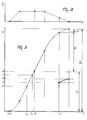
- Figure 2 shows a much simplified reproduction of a diagram of the milk flow (H/T) during a milking turn.
- the first oblique part of the diagram shows the milk stream when the milk supply of the animal is started; the horizontal part of the diagram indicates a more or less constant milk supply of the animal and the last oblique part of the diagram represents a slow decrease of the milk supply during the milking out of the animal.
- the diagram according to Figure 3 is obtained, in which the quantity of milk is set out in time.
- Figure 3 the method of determining the quantity of milk M during a milking turn will further be explained.
- the milking turn starts and milk is collected in the milk glass 2.
- the computer 8 is preprogrammed in such a way that, when the milk glass 2 contains a quantity of milk A, which can be ascertained by means of the quantity meter 11, 16, the computer 8 supplies a signal to the valve 6 and the pump 7 via the lines 9, 10 respectively, so that the valve 6 and the pump 7 are put into operation.
- an interval of time (t 2 - t 1 ) preprogrammed in the computer 8 milk is pumped out of the milk glass 2. Meanwhile, the flow of milk into the milk glass 2 via the milk supply line 3 is still possible.
- the computer-controlled valve 6 is closed and the computer-controlled pump 7 is put out of operation.
- the quantity of milk C then present in the milk glass 2 is determined and this data is stored in the computer 8.
- B can be calculated on the basis of (t 2 - t 1 ) and at least two quantity measurements in the milkmeter 1 prior to the discharge of the milk from the milkmeter 1 or thereafter and on the basis of the open interval (t 2 - t 1 ) and the points of time when these quantity measurements have been carried out, which can be recorded by means of the computer 8.
- these two quantity measurements are indicated by x and y and the points of time when they have been carried out by t x , t y .
- the quantity measurements x and y and the points of time t x and t y are already recorded in the computer 8 before the quantity of milk A is collected in the milk glass 2.
- the quantity measurements are preferably carried out in the milk glass 2 when the quantity of milk A approaches, in order better to be able to calculate B.
- a slope can also be calculated by means of at least two quantity measurements in the section between C and D in the diagram of Figure 3.
Landscapes
- Life Sciences & Earth Sciences (AREA)
- Animal Husbandry (AREA)
- Environmental Sciences (AREA)
- Physics & Mathematics (AREA)
- Fluid Mechanics (AREA)
- General Physics & Mathematics (AREA)
- Measuring Volume Flow (AREA)
- External Artificial Organs (AREA)
Applications Claiming Priority (2)
| Application Number | Priority Date | Filing Date | Title |
|---|---|---|---|
| NL1001257A NL1001257C2 (nl) | 1995-09-21 | 1995-09-21 | Werkwijze voor het bepalen van de hoeveelheid melk die tijdens een melkbeurt wordt verzameld. |
| NL1001257 | 1995-09-21 |
Publications (2)
| Publication Number | Publication Date |
|---|---|
| EP0764402A1 true EP0764402A1 (fr) | 1997-03-26 |
| EP0764402B1 EP0764402B1 (fr) | 2001-12-19 |
Family
ID=19761607
Family Applications (1)
| Application Number | Title | Priority Date | Filing Date |
|---|---|---|---|
| EP96202599A Expired - Lifetime EP0764402B1 (fr) | 1995-09-21 | 1996-09-18 | Méthode de détermination de la quantité de lait recueillie pendant une traite |
Country Status (3)
| Country | Link |
|---|---|
| EP (1) | EP0764402B1 (fr) |
| DE (1) | DE69618120T2 (fr) |
| NL (1) | NL1001257C2 (fr) |
Families Citing this family (2)
| Publication number | Priority date | Publication date | Assignee | Title |
|---|---|---|---|---|
| DE102004025059B4 (de) * | 2004-05-18 | 2006-07-13 | Hendrik Schulte-Berndt | Behälter |
| DE102006014207A1 (de) * | 2006-03-25 | 2007-09-27 | Westfaliasurge Gmbh | Milchsammeleinrichtung und Verfahren zum Betreiben einer Milchsammeleinrichtung |
Citations (3)
| Publication number | Priority date | Publication date | Assignee | Title |
|---|---|---|---|---|
| EP0057267A1 (fr) * | 1981-02-04 | 1982-08-11 | Westfalia Separator AG | Appareil pour mesurer les quantités de lait tirées d'une vache au cours de la traite |
| EP0081049A2 (fr) * | 1981-10-05 | 1983-06-15 | Westfalia Separator AG | Appareil pour mesurer directement les quantités de lait tirés d'une vache au cours de la traite |
| EP0510779A2 (fr) * | 1989-02-27 | 1992-10-28 | C. van der Lely N.V. | Installation de traite |
-
1995
- 1995-09-21 NL NL1001257A patent/NL1001257C2/nl not_active IP Right Cessation
-
1996
- 1996-09-18 DE DE69618120T patent/DE69618120T2/de not_active Expired - Lifetime
- 1996-09-18 EP EP96202599A patent/EP0764402B1/fr not_active Expired - Lifetime
Patent Citations (3)
| Publication number | Priority date | Publication date | Assignee | Title |
|---|---|---|---|---|
| EP0057267A1 (fr) * | 1981-02-04 | 1982-08-11 | Westfalia Separator AG | Appareil pour mesurer les quantités de lait tirées d'une vache au cours de la traite |
| EP0081049A2 (fr) * | 1981-10-05 | 1983-06-15 | Westfalia Separator AG | Appareil pour mesurer directement les quantités de lait tirés d'une vache au cours de la traite |
| EP0510779A2 (fr) * | 1989-02-27 | 1992-10-28 | C. van der Lely N.V. | Installation de traite |
Also Published As
| Publication number | Publication date |
|---|---|
| DE69618120T2 (de) | 2002-08-14 |
| NL1001257C2 (nl) | 1997-03-25 |
| EP0764402B1 (fr) | 2001-12-19 |
| DE69618120D1 (de) | 2002-01-31 |
Similar Documents
| Publication | Publication Date | Title |
|---|---|---|
| EP0516246B1 (fr) | Installation de traite | |
| US6167838B1 (en) | Method and an implement for automatically milking animals | |
| EP0679331A2 (fr) | Méthode de traite automatique d'animaux et appareil utilisant cette méthode | |
| US4372249A (en) | Volumetric apparatus for milk and method of measuring the total quantity of milk collected from a cow in milking | |
| US6604053B2 (en) | Method for measuring flow rate of a continuous fluid flow | |
| US4112758A (en) | Milk monitoring method and apparatus | |
| US7063043B2 (en) | Milk flow meter for a milking system having a substantially stable vacuum level and method for using same | |
| EP0795268A1 (fr) | Dispositif de mesure de quantité et dispositif de traite d'animaux muni d'un tel appareil de mesure | |
| EP0764402B1 (fr) | Méthode de détermination de la quantité de lait recueillie pendant une traite | |
| US4906165A (en) | Flow meter for a positive displacement pump | |
| EP0163730B1 (fr) | Dispositif et methode de mesure de la viscosite et/ou de la visco-elasticite d'un fluide | |
| US4608864A (en) | Device for sampling and measuring the flow rate of a continuously or intermittently circulating liquid | |
| US20030075110A1 (en) | Liquid metering | |
| CA2157943A1 (fr) | Pluviometre a siphon rgs-100 | |
| US20030140861A1 (en) | Valve | |
| AU2001240326B2 (en) | Liquid metering | |
| SU1544307A1 (ru) | Устройство дл отбора проб молока | |
| GB2079956A (en) | Method and apparatus for measuring total milk flow | |
| EP0185190A1 (fr) | Procédé pour la mesure continue de la production d'un liquide dans un mélange liquide/gaz et appareil de mesure pour l'application de ce procédé | |
| IE900428A1 (en) | A liquid metering apparatus | |
| EP1514468A1 (fr) | Méthode de traite d'un animal, et appareil à cet effet | |
| JP2001251983A (ja) | 搾乳システムの洗浄方法 | |
| NL8002770A (nl) | Correctie-inrichting in een melkmeter voor in de melk aanwezige lucht. | |
| JPH08304140A (ja) | 液量測定装置 |
Legal Events
| Date | Code | Title | Description |
|---|---|---|---|
| PUAI | Public reference made under article 153(3) epc to a published international application that has entered the european phase |
Free format text: ORIGINAL CODE: 0009012 |
|
| AK | Designated contracting states |
Kind code of ref document: A1 Designated state(s): DE FR GB NL SE |
|
| 17P | Request for examination filed |
Effective date: 19970901 |
|
| 17Q | First examination report despatched |
Effective date: 19990722 |
|
| GRAG | Despatch of communication of intention to grant |
Free format text: ORIGINAL CODE: EPIDOS AGRA |
|
| GRAG | Despatch of communication of intention to grant |
Free format text: ORIGINAL CODE: EPIDOS AGRA |
|
| GRAH | Despatch of communication of intention to grant a patent |
Free format text: ORIGINAL CODE: EPIDOS IGRA |
|
| GRAH | Despatch of communication of intention to grant a patent |
Free format text: ORIGINAL CODE: EPIDOS IGRA |
|
| GRAA | (expected) grant |
Free format text: ORIGINAL CODE: 0009210 |
|
| AK | Designated contracting states |
Kind code of ref document: B1 Designated state(s): DE FR GB NL SE |
|
| REG | Reference to a national code |
Ref country code: GB Ref legal event code: IF02 |
|
| REF | Corresponds to: |
Ref document number: 69618120 Country of ref document: DE Date of ref document: 20020131 |
|
| PLBQ | Unpublished change to opponent data |
Free format text: ORIGINAL CODE: EPIDOS OPPO |
|
| PLBI | Opposition filed |
Free format text: ORIGINAL CODE: 0009260 |
|
| PLBF | Reply of patent proprietor to notice(s) of opposition |
Free format text: ORIGINAL CODE: EPIDOS OBSO |
|
| 26 | Opposition filed |
Opponent name: DELAVAL INTERNATIONAL AB Effective date: 20020918 |
|
| PLBF | Reply of patent proprietor to notice(s) of opposition |
Free format text: ORIGINAL CODE: EPIDOS OBSO |
|
| NLR1 | Nl: opposition has been filed with the epo |
Opponent name: DELAVAL INTERNATIONAL AB |
|
| PLBF | Reply of patent proprietor to notice(s) of opposition |
Free format text: ORIGINAL CODE: EPIDOS OBSO |
|
| PLCK | Communication despatched that opposition was rejected |
Free format text: ORIGINAL CODE: EPIDOSNREJ1 |
|
| APBP | Date of receipt of notice of appeal recorded |
Free format text: ORIGINAL CODE: EPIDOSNNOA2O |
|
| APBQ | Date of receipt of statement of grounds of appeal recorded |
Free format text: ORIGINAL CODE: EPIDOSNNOA3O |
|
| APAA | Appeal reference recorded |
Free format text: ORIGINAL CODE: EPIDOS REFN |
|
| APAH | Appeal reference modified |
Free format text: ORIGINAL CODE: EPIDOSCREFNO |
|
| APBU | Appeal procedure closed |
Free format text: ORIGINAL CODE: EPIDOSNNOA9O |
|
| PLBN | Opposition rejected |
Free format text: ORIGINAL CODE: 0009273 |
|
| STAA | Information on the status of an ep patent application or granted ep patent |
Free format text: STATUS: OPPOSITION REJECTED |
|
| 27O | Opposition rejected |
Effective date: 20070112 |
|
| NLR2 | Nl: decision of opposition |
Effective date: 20070112 |
|
| PGFP | Annual fee paid to national office [announced via postgrant information from national office to epo] |
Ref country code: GB Payment date: 20090929 Year of fee payment: 14 |
|
| PGFP | Annual fee paid to national office [announced via postgrant information from national office to epo] |
Ref country code: DE Payment date: 20090929 Year of fee payment: 14 |
|
| PGFP | Annual fee paid to national office [announced via postgrant information from national office to epo] |
Ref country code: NL Payment date: 20100924 Year of fee payment: 15 |
|
| GBPC | Gb: european patent ceased through non-payment of renewal fee |
Effective date: 20100918 |
|
| REG | Reference to a national code |
Ref country code: FR Ref legal event code: ST Effective date: 20110531 |
|
| REG | Reference to a national code |
Ref country code: DE Ref legal event code: R119 Ref document number: 69618120 Country of ref document: DE Effective date: 20110401 |
|
| PG25 | Lapsed in a contracting state [announced via postgrant information from national office to epo] |
Ref country code: DE Free format text: LAPSE BECAUSE OF NON-PAYMENT OF DUE FEES Effective date: 20110401 Ref country code: FR Free format text: LAPSE BECAUSE OF NON-PAYMENT OF DUE FEES Effective date: 20100930 |
|
| PG25 | Lapsed in a contracting state [announced via postgrant information from national office to epo] |
Ref country code: GB Free format text: LAPSE BECAUSE OF NON-PAYMENT OF DUE FEES Effective date: 20100918 |
|
| PGFP | Annual fee paid to national office [announced via postgrant information from national office to epo] |
Ref country code: FR Payment date: 20091006 Year of fee payment: 14 |
|
| REG | Reference to a national code |
Ref country code: NL Ref legal event code: V1 Effective date: 20120401 |
|
| PG25 | Lapsed in a contracting state [announced via postgrant information from national office to epo] |
Ref country code: NL Free format text: LAPSE BECAUSE OF NON-PAYMENT OF DUE FEES Effective date: 20120401 |
|
| PGFP | Annual fee paid to national office [announced via postgrant information from national office to epo] |
Ref country code: SE Payment date: 20120927 Year of fee payment: 17 |
|
| REG | Reference to a national code |
Ref country code: SE Ref legal event code: EUG |
|
| PG25 | Lapsed in a contracting state [announced via postgrant information from national office to epo] |
Ref country code: SE Free format text: LAPSE BECAUSE OF NON-PAYMENT OF DUE FEES Effective date: 20130919 |