EP0764736B1 - Flügel für Sortiervorrichtungen - Google Patents
Flügel für Sortiervorrichtungen Download PDFInfo
- Publication number
- EP0764736B1 EP0764736B1 EP96115317A EP96115317A EP0764736B1 EP 0764736 B1 EP0764736 B1 EP 0764736B1 EP 96115317 A EP96115317 A EP 96115317A EP 96115317 A EP96115317 A EP 96115317A EP 0764736 B1 EP0764736 B1 EP 0764736B1
- Authority
- EP
- European Patent Office
- Prior art keywords
- vane
- wing
- base body
- section
- screen
- Prior art date
- Legal status (The legal status is an assumption and is not a legal conclusion. Google has not performed a legal analysis and makes no representation as to the accuracy of the status listed.)
- Expired - Lifetime
Links
- 238000012216 screening Methods 0.000 title description 2
- 239000011888 foil Substances 0.000 title 1
- 230000003247 decreasing effect Effects 0.000 claims abstract description 17
- 239000000725 suspension Substances 0.000 claims abstract description 7
- 230000007704 transition Effects 0.000 claims abstract description 7
- 238000004537 pulping Methods 0.000 claims abstract description 5
- 125000006850 spacer group Chemical group 0.000 claims description 3
- 230000002349 favourable effect Effects 0.000 claims 1
- 239000002657 fibrous material Substances 0.000 abstract 1
- 239000000463 material Substances 0.000 description 16
- 239000004744 fabric Substances 0.000 description 12
- 238000004140 cleaning Methods 0.000 description 11
- 239000000835 fiber Substances 0.000 description 10
- 230000000694 effects Effects 0.000 description 8
- 230000010349 pulsation Effects 0.000 description 8
- 238000000034 method Methods 0.000 description 7
- 238000013461 design Methods 0.000 description 6
- 230000007257 malfunction Effects 0.000 description 6
- 230000008859 change Effects 0.000 description 4
- 238000005265 energy consumption Methods 0.000 description 4
- 230000008569 process Effects 0.000 description 4
- 230000008719 thickening Effects 0.000 description 4
- 230000009471 action Effects 0.000 description 3
- 238000011109 contamination Methods 0.000 description 3
- 238000005243 fluidization Methods 0.000 description 3
- 239000012535 impurity Substances 0.000 description 3
- 238000009987 spinning Methods 0.000 description 3
- 230000008901 benefit Effects 0.000 description 2
- 230000003993 interaction Effects 0.000 description 2
- 238000005476 soldering Methods 0.000 description 2
- 238000003466 welding Methods 0.000 description 2
- 230000035508 accumulation Effects 0.000 description 1
- 238000009825 accumulation Methods 0.000 description 1
- 230000015572 biosynthetic process Effects 0.000 description 1
- 230000015556 catabolic process Effects 0.000 description 1
- 238000005352 clarification Methods 0.000 description 1
- 239000000356 contaminant Substances 0.000 description 1
- 238000013016 damping Methods 0.000 description 1
- 238000006731 degradation reaction Methods 0.000 description 1
- 238000011161 development Methods 0.000 description 1
- 238000005516 engineering process Methods 0.000 description 1
- 238000009434 installation Methods 0.000 description 1
- 230000002045 lasting effect Effects 0.000 description 1
- 238000012986 modification Methods 0.000 description 1
- 230000004048 modification Effects 0.000 description 1
- 238000005457 optimization Methods 0.000 description 1
- 238000003825 pressing Methods 0.000 description 1
- 230000009467 reduction Effects 0.000 description 1
- 238000007873 sieving Methods 0.000 description 1
- 230000003319 supportive effect Effects 0.000 description 1
- 238000012546 transfer Methods 0.000 description 1
- 238000011144 upstream manufacturing Methods 0.000 description 1
Images
Classifications
-
- B—PERFORMING OPERATIONS; TRANSPORTING
- B07—SEPARATING SOLIDS FROM SOLIDS; SORTING
- B07B—SEPARATING SOLIDS FROM SOLIDS BY SIEVING, SCREENING, SIFTING OR BY USING GAS CURRENTS; SEPARATING BY OTHER DRY METHODS APPLICABLE TO BULK MATERIAL, e.g. LOOSE ARTICLES FIT TO BE HANDLED LIKE BULK MATERIAL
- B07B1/00—Sieving, screening, sifting, or sorting solid materials using networks, gratings, grids, or the like
- B07B1/18—Drum screens
- B07B1/20—Stationary drums with moving interior agitators
-
- D—TEXTILES; PAPER
- D21—PAPER-MAKING; PRODUCTION OF CELLULOSE
- D21D—TREATMENT OF THE MATERIALS BEFORE PASSING TO THE PAPER-MAKING MACHINE
- D21D5/00—Purification of the pulp suspension by mechanical means; Apparatus therefor
- D21D5/02—Straining or screening the pulp
- D21D5/023—Stationary screen-drums
- D21D5/026—Stationary screen-drums with rotating cleaning foils
Definitions
- the invention relates to a wing and an arrangement of several wings for sorting devices, in particular are intended for fiber suspensions in paper pulping.
- the invention relates to preferred wing shapes.
- a wing or a Sorting wing of a sorter with a drum-like body known.
- the wing points in the direction of rotation ever increasing cross section and ends in one steep edge, and this is included in the direction of rotation Extension with a decreasing cross-section with a Fillet.
- the area with increasing cross section forms in Interaction with a surrounding the drum-like body Sieve wall a suction zone, and the area with decreasing Cross section forms in cooperation with the screen wall Pressure zone.
- the outer contour of the wing includes a steep one falling edge at the transition between the area with increasing Cross section and the area with decreasing cross section.
- WO90 / 05807 and US-A-2 835 173 are sorting devices known, which have a rotor that on its outer circumference Cleaning elements or sorting elements is occupied.
- the above installation of the same can also be fiber bundles and braids as well as dead zones and spinning due to the Form the disruptive effect of the cleaning elements in the material flow area.
- the Annular gap between the screen wall and the rotor base body due to the projecting height of the cleaning elements or Driving elements narrowed. If between the highest point of the Cleaning element and the sieve wall surface only a small one If there is a distance, the goods to be treated can be on this very narrowed, annular gap a very strong Experience thickening. This leads to malfunctions of the Sorter. However, if you arrange such a rotor at a greater distance from the screen wall, so you have to Increase the speed of the rotor, reducing the energy consumption of the Sorting device becomes larger.
- the invention aims to achieve the one outlined above Need to take into account and especially while overcoming of the difficulties described above wings for sorting devices to provide, especially for fiber suspensions are determined when digesting paper and which in supportive An efficient and reliable manner high quality sorting with an energy saving Allow operation.
- a wing for sorting device especially for fiber suspensions in paper pulping, provided which faces such a screen wall Outside contour has that in cooperation with the screen wall in Flow direction a suction zone section with increasing Wing width and a pressure zone section with decreasing Wing width forms, whereby the total length of the wing the length of the suction zone section and the length of the pressure zone section composed.
- the wing according to the invention thus has to face the screen Outside contour profiling without edges, breaks or Fillets, but with both the section of the wing increasing wing width as well as the section of the wing decreasing wing width and also the transition area a steady course. This is also in the area of the pressure zone section a steady increase in pressure due to the steady course available, which ensures gentle transport of material to the perforations the screen wall takes place. This prevents Contamination in the pressure zone section due to the perforations the screen wall to be pressed. So you get an improved one Sorting quality. At the same time, you also get the necessary ones Turbulence to keep and clean the perforations as well sufficient fluidization of the goods to be sorted due to the change in sash width in the suction zone section.
- the sorting device especially suitable for sorting tasks in High consistency area, as well as for sorting tasks with quite coarse impurities, since the sorting quality can significantly improve.
- the total length Fl des are further influencing variables Wing, based on the inside diameter of the screen, as well as the largest Wing width Fb to mention.
- the total length Fl based on the Sieve inner diameter Di, is about the order of 0.05 to 0.3 x Di, preferably from 0.08 to 0.2 x Di.
- the order of magnitude for the influencing variables of the wing in the Suction zone section has such a sufficient length that reliable cleaning of the perforations of the screen wall is guaranteed. If the suction zone section is too short, the current breaks off too soon and turbulence occurs, which affect the cleaning effect.
- the smallest distance s between the Outer contour of the wing and the sieve wall about 0.5 to 10 mm, preferably 1.5 to 6 mm.
- Such a distance is essential smaller than with conventional designs of such sorters, so that you can get very high quality sorting results without Can cause malfunctions.
- the rotor speed can also be changed lower because the wings are reduced due to the Distance very effectively with regard to the fabric flow area the cleaning and fabric management act.
- the sorting device works, it can be turned away from the screen Page designed so that they are essentially with the shape of the screen-facing outer contour according to the the above explanations. You then get one symmetrical design of the wing.
- the screen facing away Side of the wing deviates from the screen facing Be designed outer contour.
- the one facing away from the screen Side be formed as a straight section.
- the wing is aerodynamically profiled. This can reduce the wing's inherent flow resistance and the energy consumption can continue to reduce. This also allows interference flows in the Suppress fabric flow area to reduce the fabric flow both on the Favor cleaning side as well as on the fabric feed side.
- the wing can be designed in several parts. If he Wing is designed in one piece or in several parts, depends on essentially on the size of the wing and its function and arrangement, for example on a base body.
- the section with increasing wing width and the section with decreasing wing width in the fabric flow direction or point against it are independent of the relative direction of movement between screen wall and wing with the wing according to the invention, the desired effects generate on the fabric flow.
- the wing can for example directly on the outer circumference of a base body, such as a basic rotor body, preferably essentially one cylindrical or conical rotor body, attached or be formed in one piece with the base body, or optionally attached to the base body by means of a support arm his. If the wing on the outer circumference of the main body attached and fastened there, so the attachment by welding or soldering, or it can be screwed on become. If the wing or wings directly on the Mounted on the outer circumference of the basic rotor body and fastened there there are no protruding internals, so that dead zones, Avoid spinning, braid formation or the like.
- the wing can face the generatrix of the base body be arranged inclined. This can create transition areas between individual sorting levels.
- this can opposite the tangent to the base body at an angle be employed, which is up to 10 °, or preferably up to 4 °, can be.
- an arrangement is specified according to the invention, which comprises several wings, which is characterized in that the Wing in different basic body axial planes in the circumferential direction are staggered.
- the invention relates to the design and Profiling of wings in sorting devices for fiber suspensions, especially for pulping paper, which such are optimized and chosen so that you have a streamlined Profiling the outer contour of the wing or wings without sharp Edges. This reduces the inherent resistance, and you get a significant energy saving. Further can through the section with ever increasing wing width and the section with continuously decreasing wing width, whereby both sections also merge continuously, on the one hand a suction zone in cooperation with the screen wall facing are formed, which for effective sieve cleaning provides sufficient suction, and on the other hand a Pressure zone are formed, which is a gentle material transport to the perforations of the screen wall without a sudden increase in pressure allowed. This makes the sorting quality essential improve.
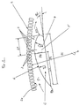
- the wing 5 has an overall outer contour 6, which the Screen wall 2a facing, which has such a course, that in cooperation with the sieve wall 2a in the material flow direction (see arrow in Figures 1 and 2) a suction zone section C with increasing wing width and a pressure zone section D with decreasing wing width is formed.
- the suction zone itself is with P- and the pressure zone with P +.
- the wing 5 has one Total wing length Fl, which is equal to the sum of the length L1 of the Suction zone section C and the length L2 of the pressure zone section D is.
- the length L1 of the pressure zone section D is 0.1 to 0.45 x Fl (total wing length) and preferably to 0.3 x Fl.
- the largest wing width is designated with Fb. This will be between the side of wing 5 facing away from the screen and the highest point measured on the outer contour 6 of the wing 5.
- the leading end of the wing 5 is preferably one immediately adjacent circular section formed or runs out with a radius R3, which is in a range of 3 to 25 mm, in particular from 6 to 20 mm.
- the outer contour 6 of the wing 5 in the suction zone section C is preferably formed by a segment of a circle, which one Has radius R1.
- At the beginning of Suction zone section C, that is, at the trailing end of the Outer contour 6 may have a radius R4 which is in one Range of 1 to 5 mm, preferably in a range of 1.5 to 3 mm.
- the smallest distance between the screen wall 2a and the outer contour 6 is denoted by s.
- This distance s can be in a range from 0.5 to 10 mm, preferably from about 1.5 to about 6 mm lie.
- an angle of attack FW can be arranged, which in one area of up to 10 °, preferably up to 4 °.
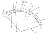
- a base body for example a rotor base body (see reference number 1 in Figure 2) then employed including the angle of attack FW.
- the wing 5 which is also referred to as a hydrofoil, enables interaction with perforations 3 in the sieve 2 regardless of the profiling of the perforations on the manner described in more detail below.
- suction zone section C In the area of the suction zone P- (suction zone section C in the figures) turbulence in the area of the perforations 3 to keep clear and cleaning as well as for feeding the material through the perforations 3 generated. Due to the increasing wing width in the suction zone section C is a gentle mass transfer to the in Perforation nearest fabric flow direction 3. Starting from the Place with the largest wing width is then also a constant pressure build-up in the pressure zone section D, so that in more efficiently in the pressure zone P + the fabric through the Perforations 3 is promoted.
- the sorting quality can be improved since for example, preventing contamination by a sudden pressure increase through the perforations 3 pressed become.
- the more efficient mode of action achieved by the Profiling of the wing 5 according to the type described above and the streamlined profile of the outer contour 6, can the energy consumption of the assigned sorting device decrease. Due to the streamlined profile of the Wing 5, the inherent resistance of the same can be reduced, and there are dead zones, spinning, braids and the like avoiding either a degradation of the efficiency of the sorting device or can even lead to malfunctions and the perforations 3 can clog.
- the wing 5 allows a efficient sorting process with high quality results as well as an energy-saving, reliable operation an assigned sorting device.
- FIG. 2 shows a preferred embodiment of a sorting device shown schematically and by way of example.
- the sorting device has a rotor with a Rotor base body 1, which is, for example, corresponding to the Direction of material flow (see arrow) in Figure 2 clockwise rotates.
- the basic rotor body 1 can be essentially cylindrical or be conical or frustoconical.
- the Rotor base body 1 is surrounded by the screen 2, which the Sieve wall 2a forms which perforations 3, such as openings, Slots or the like.
- perforations 3 such as openings, Slots or the like.
- the profile geometry of the perforations 3 for example be chosen in the manner shown in US-A-5,073,254.
- the grooves are curved in an arc and have a downstream flank with a stronger one Curvature as well as an upstream flank with weaker Curvature, with the flanks bump-free through an arc can be connected.
- On an outer circumference 4 of the Rotor base body 1 are in the example shown, in Circumferentially spaced wings 5 placed and, as there shown, for example by means of welding or soldering the rotor base body 1 firmly connected.
- wing 5 and Base body 1 can also be selected a screw connection, or if necessary, the wings 5 by means of support arms on Base body 1 be attached.
- spacers such as shims or the like, in addition to Attachment of the wing 5 to the rotor base body 1 used be, if necessary, the smallest distance s between the Screen wall 2a and the outer contour 6 of the wing 5 to vary and to adjust to the size ranges mentioned above.
- the base body 1 can with the fixed wings 5 are fixed at the sorting device, and the sieve 2 can move around the common central axis turn the arrangement of sieve 2 and base body 1.
- each wing 5 on different axial planes of the Base body 1 is arranged.
- Each wing 5 can for example inclined with respect to the generatrix of the base body 1 be arranged.
- the wings 5 are preferably different Axial planes of the base body 1 offset relative to one another arranged.
Landscapes
- Engineering & Computer Science (AREA)
- Mechanical Engineering (AREA)
- Paper (AREA)
- Holo Graphy (AREA)
- Discharge Of Articles From Conveyors (AREA)
- Separation Of Solids By Using Liquids Or Pneumatic Power (AREA)
- Combined Means For Separation Of Solids (AREA)
- Investigating Strength Of Materials By Application Of Mechanical Stress (AREA)
Description
- Die Länge L1 des Flügels im Druckzonenabschnitt, welche etwa L1 = 0,1 - 0,45 x Fl (Gesamtflügellänge), vorzugsweise etwa L1 = 0,3 x Fl, beträgt;
- der Flügel im Druckzonenabschnitt einen Radius R2 hat, welcher etwa R2 = 0,3 - 0,6 x Fl, vorzugsweise R2 = 0,4 - 0,5 x Fl beträgt;
- das vorauslaufende Ende des Flügels im Saugzonenabschnitt mit einem Radius R3 ausläuft, welcher in der Größenordnung von 3 - 25 mm, vorzugsweise 6 bis 20 mm liegt.
- Der Flügel hat im Saugzonenabschnitt einen Radius R1, welcher etwa R1 = 0,8 - 1,5 x Fl, vorzugsweise 0,9 - 1,4 x Fl beträgt;
- das nachlaufende Ende des Flügels weist vorzugsweise einen Radius R4 in der Größenordnung von 1 bis 5 mm, vorzugsweise 1,5 bis 3 mm auf.
- Fig. 1
- einen schematischen Ausschnitt einer Draufsicht auf eine Anordnung umfassend einen Flügel und eine zugeordnete Siebwand bei einer Sortiervorrichtung, und
- Fig. 2
- einen schematischen Ausschnitt einer Draufsicht auf eine Ausführungsform mit mehreren Flügeln auf dem Außenumfang eines Grundkörpers, insbesondere eines Rotorgrundkörpers.
- 1
- zylindrischer Rotorgrundkörper
- 2
- Sieb
- 3
- Perforationen
- 4
- Außenumfang des zylindrischen Rotorgrundkörpers 1
- 5
- Sortierflügel
- 6
- Außenkontur des Flügels 5
- S
- siebnächster Punkt
- s
- Abstand
- FW
- Anstellwinkel
- C
- im Querschnitt zunehmender Bereich
- D
- im Querschnitt abnehmender Bereich
- P+
- Druckzone
- P-
- Saugzone
- F1
- Gesamtflügellänge
- L1
- Flügellänge des Druckzonenabschnitts D
- L2
- Flügellänge des Saugzonenabschnitts C
- Fb
- Flügelbreite
Claims (21)
- Flügel für Sortiervorrichtungen, insbesondere für Fasersuspensionen beim Papieraufschluß, welcher eine derartige, einer Siebwand zugewandte Außenkontur hat, daß er im Zusammenwirken mit der Siebwand in Stofflußrichtung einen Saugzonenabschnitt (C) mit zunehmender Flügelbreite, und einen Druckzonenabschnitt (D) mit abnehmender Flügelbreite bildet, wobei sich die Gesamtlänge (FI) des Flügels (5) aus der Länge des Saugzonenabschnitts (C) und der Länge (L1) des Druckzonenabschnitts (D) zusammensetzt und die siebzugewandte Außenkontur (6) des Flügels (5) einen stetigen Verlauf von zunehmender Flügelbreite und abnehmender Flügelbreite auch am Übergangsbereich hat, dadurch gekennzeichnet, daß die Länge (L1) des Flügels (5) im Druckzonenabschnitt (D) etwa L1 = 0,1 bis 0,45 x FI (Gesamtflügellänge) beträgt, die Länge (L1) des Flügels (5) im Druckzonenabschnitt (D) etwa L1 = 0,1 bis 0,45 x FI (Gesamtflügellänge) etwa L1 = 0,3 x FI, beträgt, der Flügel (5) im Saugzonenabschnitt (C) einen Radius (R1) mit etwa R1= 0,8 bis 1,5 x FI, vorzugsweise R1 = 0,9 bis 1,4 x FI, hat, und daß die größte Flügelbreite (Fb) etwa Fb = 0,15 bis 0,35 x FI, vorzugsweise Fb = 0,2 bis 0,27 x FI, beträgt.
- Flügel nach Anspruch 1, dadurch gekennzeichnet, daß der Flügel (5) im Druckzonenabschnitt (D) einen Radius (R2) mit etwa R2 = 0,3 bis 0,6 x FI, vorzugsweise R2 = 0,4 bis 0,5 x FI, hat.
- Flügel nach Anspruch 1 oder 2, dadurch gekennzeichnet, daß die Gesamtlänge (FI) des Flügels (5) bezogen auf den Siebinnendurchmesser (Di) etwa in der Größenordnung von FI = 0,05 bis 0,3 x Di, vorzugsweise FI = 0,08 bis 0,2 x Di, liegt.
- Flügel nach einem der vorangehenden Ansprüche, dadurch gekennzeichnet, daß der Abschnitt des Flügels (5) mit abnehmender Flügelbreite mit einem Radius (R3) in der Größenordnung von 3 bis 25 mm, vorzugsweise von 6 bis 20 mm, ausläuft.
- Flügel nach einem der vorangehenden Ansprüche, dadurch gekennzeichnet, daß der Abschnitt des Flügels (5) mit zunehmender Flügelbreite mit einem Radius (R4) in der Größenordnung von 1 bis 5 mm, vorzugsweise von 1,5 bis 3 mm, beginnt.
- Flügel nach einem der vorangehenden Ansprüche, dadurch gekennzeichnet, daß der kleinste Abstand (s) zwischen der Außenkontur (6) des Flügels (5) und der Siebwand (2a) etwa 0,5 bis 10 mm, vorzugsweise 1,5 bis 6 mm, beträgt.
- Flügel nach einem der vorangehenden Ansprüche, dadurch gekennzeichnet, daß die siebabgewandte Seite des Flügels (5) im wesentlichen mit der Gestalt der siebzugewandten Außenkontur (6) übereinstimmt.
- Flügel nach einem der Ansprüche 1 bis 6, dadurch gekennzeichnet, daß die siebabgewandte Seite des Flügels (5) abweichend von der siebzugewandten Außenkontur (6) ausgebildet ist.
- Flügel nach einem der vorangehenden Ansprüche, dadurch gekennzeichnet, daß er strömungsgünstig profiliert ist.
- Flügel nach einem der vorangehenden Ansprüche, dadurch gekennzeichnet, daß er mehrteilig ausgelegt ist.
- Flügel nach einem der vorangehenden Ansprüche, dadurch gekennzeichnet, daß der Abschnitt (C) mit zunehmender Flügelbreite und der Abschnitt (D) mit abnehmender Flügelbreite in Stofflußrichtung oder entgegen derselben weisen.
- Flügel nach einem der vorangehenden Ansprüche, dadurch gekennzeichnet, daß er auf einem Außenumfang (4) eines Grundkörpers (1) befestigt oder einteilig mit dem Grundkörper (1) ausgebildet ist.
- Flügel nach Anspruch 12, dadurch gekennzeichnet, daß der Grundkörper (1) ein Rotorgrundkörper, vorzugsweise ein im wesentlichen zylindrischer oder kegelförmiger Rotorgrundkörper, ist.
- Flügel nach Anspruch 12 oder 13, dadurch gekennzeichnet, daß er gegenüber der Erzeugenden des Grundkörpers (1) geneigt ist.
- Flügel nach einem der Ansprüche 12 bis 14, dadurch gekennzeichnet, daß er gegenüber der Tangente an den Grundkörper (1) unter einem Winkel (FW) von bis zu 10°, vorzugsweise bis zu 4°, angestellt ist.
- Flügel nach einem der vorangehenden Ansprüche, dadurch gekennzeichnet, daß er direkt auf den Außenumfang (4) des Grundkörpers (1) aufgesetzt und befestigt ist.
- Flügel nach Anspruch 16, dadurch gekennzeichnet, daß er angeschweißt oder angelötet ist.
- Flügel nach einem der Ansprüche 12 bis 15, dadurch gekennzeichnet, daß er am Grundkörper (1) mittels eines Tragarms befestigt ist.
- Flügel nach einem der Ansprüche 12 bis 18, dadurch gekennzeichnet, daß er am Grundkörper (1) oder vermittels des Tragarms angeschraubt ist.
- Flügel nach Anspruch 19, dadurch gekennzeichnet, daß zur Veränderung des kleinsten Abstandes (s) zwischen der Außenkontur (6) des Flügels (5) und der Siebwand (2a) Distanzstücke, wie Beilagebleche oder dergleichen, vorgesehen sind.
- Anordnung, umfassend mehrere Flügel, nach einem der Ansprüche 12 bis 20, dadurch gekennzeichnet, daß die Flügel (5) in unterschiedlichen Grundkörperaxialebenen in Umfangsrichtung versetzt angeordnet sind.
Applications Claiming Priority (2)
| Application Number | Priority Date | Filing Date | Title |
|---|---|---|---|
| DE29515338U | 1995-09-25 | ||
| DE29515338U DE29515338U1 (de) | 1995-09-25 | 1995-09-25 | Flügel für Sortiervorrichtungen |
Publications (3)
| Publication Number | Publication Date |
|---|---|
| EP0764736A2 EP0764736A2 (de) | 1997-03-26 |
| EP0764736A3 EP0764736A3 (de) | 1997-07-02 |
| EP0764736B1 true EP0764736B1 (de) | 2002-03-06 |
Family
ID=8013433
Family Applications (1)
| Application Number | Title | Priority Date | Filing Date |
|---|---|---|---|
| EP96115317A Expired - Lifetime EP0764736B1 (de) | 1995-09-25 | 1996-09-24 | Flügel für Sortiervorrichtungen |
Country Status (5)
| Country | Link |
|---|---|
| EP (1) | EP0764736B1 (de) |
| AT (1) | ATE214114T1 (de) |
| CA (1) | CA2186328C (de) |
| DE (2) | DE29515338U1 (de) |
| ES (1) | ES2173233T3 (de) |
Cited By (3)
| Publication number | Priority date | Publication date | Assignee | Title |
|---|---|---|---|---|
| WO2008119880A1 (en) | 2007-03-30 | 2008-10-09 | Advanced Fiber Technologies (Aft) Oy | Rotor element and a rotor for a screening apparatus |
| DE102009014810A1 (de) | 2009-03-25 | 2010-09-30 | Andritz Fiedler Gmbh | Flügel für Sortiervorrichtungen |
| US10617979B2 (en) | 2012-05-25 | 2020-04-14 | Aikawa Fiber Technologies Trust | Rotor element and a rotor for a screening apparatus |
Families Citing this family (7)
| Publication number | Priority date | Publication date | Assignee | Title |
|---|---|---|---|---|
| DE29515338U1 (de) * | 1995-09-25 | 1995-11-23 | Heinrich Fiedler GmbH & Co. KG, 93057 Regensburg | Flügel für Sortiervorrichtungen |
| FI102980B1 (fi) * | 1997-05-21 | 1999-03-31 | Valmet Corp | Siipisovitelma kuitumassan lajittelulaitetta varten |
| FI4401U1 (fi) † | 1999-11-29 | 2000-04-27 | Ahlstrom Machinery Oy | Järjestely massan lajittelemiseksi |
| FI118478B (fi) | 2006-02-10 | 2007-11-30 | Metso Paper Inc | Lajittimen siipi ja lajitin kuitumassan lajittelemiseksi |
| FI120913B (fi) † | 2007-09-28 | 2010-04-30 | Andritz Oy | Laite massan lajittelemiseksi |
| FI121672B (fi) | 2008-10-15 | 2011-02-28 | Advanced Fiber Tech Aft Trust | Menetelmä lajitinlaitteen roottorin valmistamiseksi ja roottori |
| CN115198553B (zh) * | 2021-04-12 | 2025-08-22 | 安德里茨(中国)有限公司 | 浆料筛选转子及浆料筛选设备 |
Family Cites Families (12)
| Publication number | Priority date | Publication date | Assignee | Title |
|---|---|---|---|---|
| DE495284C (de) * | 1925-05-23 | 1930-04-04 | Samuel Milne | Verfahren und Einrichtung zum Sichten von Papierstoff u. dgl. |
| US2835173A (en) * | 1955-03-03 | 1958-05-20 | Black Clawson Co | Paper machinery |
| DE1250726B (de) * | 1963-05-17 | 1967-09-21 | Canadian Ingersoll-Rand Company Limited, Montreal, Quebec (Kana da), Bird Machine Company, South Walpole, Mass (V St A) | Reinigungsvorrichtung fur Trommelsiebe |
| DE1761853A1 (de) * | 1968-07-15 | 1971-09-02 | Feldmuehle Ag | Verfahren zum Herstellen flaechiger Vliesstoffe |
| DE2830386C2 (de) * | 1978-07-11 | 1982-09-02 | Hermann Finckh, Maschinenfabrik GmbH & Co, 7417 Pfullingen | Verfahren zum Sortieren von Fasersuspensionen sowie Drucksortierer zur Durchführung des Verfahrens |
| DE3010952A1 (de) * | 1980-03-21 | 1981-10-08 | J.M. Voith Gmbh, 7920 Heidenheim | Scheibensortierer zum reinigen von faserstoffsuspensionen |
| DE3607457A1 (de) * | 1986-03-07 | 1987-09-10 | Voith Gmbh J M | Sortiersieb |
| DE4000248A1 (de) * | 1990-01-06 | 1991-07-11 | Emil Holz | Rotor fuer drucksortierer zum sortieren von fasersuspensionen |
| US5072834A (en) * | 1990-11-19 | 1991-12-17 | The Black Clawson Company | Screening apparatus for paper making stock |
| US5282579A (en) * | 1993-01-25 | 1994-02-01 | Poser Kimberly J | Apparatus for adjusting the gap of a size reduction machine |
| JP3065202B2 (ja) * | 1993-10-20 | 2000-07-17 | 石川島播磨重工業株式会社 | 古紙パルプの選別方法および装置 |
| DE29515338U1 (de) * | 1995-09-25 | 1995-11-23 | Heinrich Fiedler GmbH & Co. KG, 93057 Regensburg | Flügel für Sortiervorrichtungen |
-
1995
- 1995-09-25 DE DE29515338U patent/DE29515338U1/de not_active Expired - Lifetime
-
1996
- 1996-09-24 AT AT96115317T patent/ATE214114T1/de active
- 1996-09-24 EP EP96115317A patent/EP0764736B1/de not_active Expired - Lifetime
- 1996-09-24 CA CA002186328A patent/CA2186328C/en not_active Expired - Fee Related
- 1996-09-24 DE DE59608825T patent/DE59608825D1/de not_active Expired - Lifetime
- 1996-09-24 ES ES96115317T patent/ES2173233T3/es not_active Expired - Lifetime
Cited By (4)
| Publication number | Priority date | Publication date | Assignee | Title |
|---|---|---|---|---|
| WO2008119880A1 (en) | 2007-03-30 | 2008-10-09 | Advanced Fiber Technologies (Aft) Oy | Rotor element and a rotor for a screening apparatus |
| DE102009014810A1 (de) | 2009-03-25 | 2010-09-30 | Andritz Fiedler Gmbh | Flügel für Sortiervorrichtungen |
| US10617979B2 (en) | 2012-05-25 | 2020-04-14 | Aikawa Fiber Technologies Trust | Rotor element and a rotor for a screening apparatus |
| US11135532B2 (en) | 2012-05-25 | 2021-10-05 | Aikawa Fiber Technologies Inc. | Rotor element and a rotor for a screening apparatus |
Also Published As
| Publication number | Publication date |
|---|---|
| CA2186328A1 (en) | 1997-03-26 |
| DE59608825D1 (de) | 2002-04-11 |
| EP0764736A2 (de) | 1997-03-26 |
| ATE214114T1 (de) | 2002-03-15 |
| ES2173233T3 (es) | 2002-10-16 |
| CA2186328C (en) | 2008-02-12 |
| EP0764736A3 (de) | 1997-07-02 |
| DE29515338U1 (de) | 1995-11-23 |
Similar Documents
| Publication | Publication Date | Title |
|---|---|---|
| DE69013523T2 (de) | Sieb mit verbessertem abnutzungswiderstand und dessen herstellungsverfahren. | |
| DE69311898T3 (de) | Vorrichtung zur behandlung von fasersuspensionen | |
| EP0764736B1 (de) | Flügel für Sortiervorrichtungen | |
| EP0289020A2 (de) | Verfahren und Vorrichtung zum Behandeln einer Faseraufschwemmung | |
| EP1143065B1 (de) | Sortierer und Flügel für die Papiererzeugung | |
| EP0034780A2 (de) | Rotationssortierer | |
| DE69113932T2 (de) | Drucksortierer für eine faserhaltige Stoffsuspension. | |
| DE602004006019T2 (de) | Sortiervorrichtung zur sortierung von zellstoffsuspensionen und betriebsverfahren für die vorrichtung | |
| DE2830386C2 (de) | Verfahren zum Sortieren von Fasersuspensionen sowie Drucksortierer zur Durchführung des Verfahrens | |
| EP0646199A1 (de) | Drucksortierer für fasersuspensionen. | |
| DE69618669T2 (de) | Siebzylinder | |
| DE2547017A1 (de) | Zerfaserungsvorrichtung fuer papierstoff | |
| DE69314034T2 (de) | Siebvorrichtung für faserbrei | |
| EP0146641B1 (de) | Sortiersieb für Fasersuspensionen | |
| WO2012084562A1 (de) | Drucksortierer | |
| DE60105359T2 (de) | Sortierapparat für eine Fasersuspension | |
| EP0731210A2 (de) | Mahlmaschine und Mahlwerkzeug zum Mahlen von suspendiertem Faserstoffmaterial | |
| DE19911884A1 (de) | Drucksortierer zum Sieben einer Papierfaserstoffsuspension und Siebräumer für einen solchen | |
| DE69003953T2 (de) | Siebblech zum sieben von pulpe. | |
| EP0094022A2 (de) | Rotor für Sortierapparate zur Reinigung von Fasersuspensionen, insbesondere solchen der Papierindustrie | |
| DE3016211A1 (de) | Siebabscheider fuer papierstoff | |
| AT514845B1 (de) | Rotorelement und Rotor für eine Siebvorrichtung | |
| WO2020193003A1 (de) | Drucksortierer, siebelement und verfahren zur herstellung eines siebelements | |
| EP3790669B1 (de) | Siebvorrichtung | |
| WO2019206530A1 (de) | Stoffauflöser |
Legal Events
| Date | Code | Title | Description |
|---|---|---|---|
| PUAI | Public reference made under article 153(3) epc to a published international application that has entered the european phase |
Free format text: ORIGINAL CODE: 0009012 |
|
| AK | Designated contracting states |
Kind code of ref document: A2 Designated state(s): AT CH DE ES FI FR GB IT LI SE |
|
| PUAL | Search report despatched |
Free format text: ORIGINAL CODE: 0009013 |
|
| AK | Designated contracting states |
Kind code of ref document: A3 Designated state(s): AT CH DE ES FI FR GB IT LI SE |
|
| 17P | Request for examination filed |
Effective date: 19971216 |
|
| 17Q | First examination report despatched |
Effective date: 19991022 |
|
| GRAG | Despatch of communication of intention to grant |
Free format text: ORIGINAL CODE: EPIDOS AGRA |
|
| GRAG | Despatch of communication of intention to grant |
Free format text: ORIGINAL CODE: EPIDOS AGRA |
|
| GRAH | Despatch of communication of intention to grant a patent |
Free format text: ORIGINAL CODE: EPIDOS IGRA |
|
| GRAH | Despatch of communication of intention to grant a patent |
Free format text: ORIGINAL CODE: EPIDOS IGRA |
|
| REG | Reference to a national code |
Ref country code: GB Ref legal event code: IF02 |
|
| GRAA | (expected) grant |
Free format text: ORIGINAL CODE: 0009210 |
|
| AK | Designated contracting states |
Kind code of ref document: B1 Designated state(s): AT CH DE ES FI FR GB IT LI SE |
|
| REF | Corresponds to: |
Ref document number: 214114 Country of ref document: AT Date of ref document: 20020315 Kind code of ref document: T |
|
| REG | Reference to a national code |
Ref country code: CH Ref legal event code: NV Representative=s name: PA ALDO ROEMPLER Ref country code: CH Ref legal event code: EP |
|
| GBT | Gb: translation of ep patent filed (gb section 77(6)(a)/1977) |
Effective date: 20020306 |
|
| REF | Corresponds to: |
Ref document number: 59608825 Country of ref document: DE Date of ref document: 20020411 |
|
| PGFP | Annual fee paid to national office [announced via postgrant information from national office to epo] |
Ref country code: GB Payment date: 20020902 Year of fee payment: 7 |
|
| PGFP | Annual fee paid to national office [announced via postgrant information from national office to epo] |
Ref country code: CH Payment date: 20020920 Year of fee payment: 7 |
|
| PGFP | Annual fee paid to national office [announced via postgrant information from national office to epo] |
Ref country code: ES Payment date: 20020926 Year of fee payment: 7 |
|
| REG | Reference to a national code |
Ref country code: ES Ref legal event code: FG2A Ref document number: 2173233 Country of ref document: ES Kind code of ref document: T3 |
|
| PLBQ | Unpublished change to opponent data |
Free format text: ORIGINAL CODE: EPIDOS OPPO |
|
| PLAV | Examination of admissibility of opposition |
Free format text: ORIGINAL CODE: EPIDOS OPEX |
|
| PLBI | Opposition filed |
Free format text: ORIGINAL CODE: 0009260 |
|
| PLBQ | Unpublished change to opponent data |
Free format text: ORIGINAL CODE: EPIDOS OPPO |
|
| PLAV | Examination of admissibility of opposition |
Free format text: ORIGINAL CODE: EPIDOS OPEX |
|
| PLBF | Reply of patent proprietor to notice(s) of opposition |
Free format text: ORIGINAL CODE: EPIDOS OBSO |
|
| 26 | Opposition filed |
Opponent name: ADVANCED FIBER TECHNOLOGIES (AFT) OY Effective date: 20021206 Opponent name: METSO PAPER VALKEAKOSKI OY Effective date: 20021205 |
|
| PLBF | Reply of patent proprietor to notice(s) of opposition |
Free format text: ORIGINAL CODE: EPIDOS OBSO |
|
| PLAX | Notice of opposition and request to file observation + time limit sent |
Free format text: ORIGINAL CODE: EPIDOSNOBS2 |
|
| PG25 | Lapsed in a contracting state [announced via postgrant information from national office to epo] |
Ref country code: GB Free format text: LAPSE BECAUSE OF NON-PAYMENT OF DUE FEES Effective date: 20030924 |
|
| PG25 | Lapsed in a contracting state [announced via postgrant information from national office to epo] |
Ref country code: ES Free format text: LAPSE BECAUSE OF NON-PAYMENT OF DUE FEES Effective date: 20030925 |
|
| PG25 | Lapsed in a contracting state [announced via postgrant information from national office to epo] |
Ref country code: LI Free format text: LAPSE BECAUSE OF NON-PAYMENT OF DUE FEES Effective date: 20030930 Ref country code: CH Free format text: LAPSE BECAUSE OF NON-PAYMENT OF DUE FEES Effective date: 20030930 |
|
| PLBB | Reply of patent proprietor to notice(s) of opposition received |
Free format text: ORIGINAL CODE: EPIDOSNOBS3 |
|
| GBPC | Gb: european patent ceased through non-payment of renewal fee |
Effective date: 20030924 |
|
| REG | Reference to a national code |
Ref country code: CH Ref legal event code: PL |
|
| REG | Reference to a national code |
Ref country code: ES Ref legal event code: FD2A Effective date: 20030925 |
|
| RAP2 | Party data changed (patent owner data changed or rights of a patent transferred) |
Owner name: ANDRITZ FIEDLER GMBH & CO. KG |
|
| PG25 | Lapsed in a contracting state [announced via postgrant information from national office to epo] |
Ref country code: IT Free format text: LAPSE BECAUSE OF NON-PAYMENT OF DUE FEES;WARNING: LAPSES OF ITALIAN PATENTS WITH EFFECTIVE DATE BEFORE 2007 MAY HAVE OCCURRED AT ANY TIME BEFORE 2007. THE CORRECT EFFECTIVE DATE MAY BE DIFFERENT FROM THE ONE RECORDED. Effective date: 20050924 |
|
| PLCK | Communication despatched that opposition was rejected |
Free format text: ORIGINAL CODE: EPIDOSNREJ1 |
|
| PLBN | Opposition rejected |
Free format text: ORIGINAL CODE: 0009273 |
|
| STAA | Information on the status of an ep patent application or granted ep patent |
Free format text: STATUS: OPPOSITION REJECTED |
|
| 27O | Opposition rejected |
Effective date: 20070329 |
|
| PGFP | Annual fee paid to national office [announced via postgrant information from national office to epo] |
Ref country code: FR Payment date: 20111005 Year of fee payment: 16 Ref country code: DE Payment date: 20110921 Year of fee payment: 16 Ref country code: FI Payment date: 20110922 Year of fee payment: 16 Ref country code: AT Payment date: 20110922 Year of fee payment: 16 Ref country code: SE Payment date: 20110923 Year of fee payment: 16 |
|
| PG25 | Lapsed in a contracting state [announced via postgrant information from national office to epo] |
Ref country code: FI Free format text: LAPSE BECAUSE OF NON-PAYMENT OF DUE FEES Effective date: 20120924 Ref country code: SE Free format text: LAPSE BECAUSE OF NON-PAYMENT OF DUE FEES Effective date: 20120925 |
|
| REG | Reference to a national code |
Ref country code: SE Ref legal event code: EUG |
|
| REG | Reference to a national code |
Ref country code: AT Ref legal event code: MM01 Ref document number: 214114 Country of ref document: AT Kind code of ref document: T Effective date: 20120924 |
|
| REG | Reference to a national code |
Ref country code: FR Ref legal event code: ST Effective date: 20130531 |
|
| PG25 | Lapsed in a contracting state [announced via postgrant information from national office to epo] |
Ref country code: DE Free format text: LAPSE BECAUSE OF NON-PAYMENT OF DUE FEES Effective date: 20130403 Ref country code: AT Free format text: LAPSE BECAUSE OF NON-PAYMENT OF DUE FEES Effective date: 20120924 |
|
| PG25 | Lapsed in a contracting state [announced via postgrant information from national office to epo] |
Ref country code: FR Free format text: LAPSE BECAUSE OF NON-PAYMENT OF DUE FEES Effective date: 20121001 |
|
| REG | Reference to a national code |
Ref country code: DE Ref legal event code: R119 Ref document number: 59608825 Country of ref document: DE Effective date: 20130403 |