EP0764781A2 - Chambre d'admission - Google Patents
Chambre d'admission Download PDFInfo
- Publication number
- EP0764781A2 EP0764781A2 EP96114588A EP96114588A EP0764781A2 EP 0764781 A2 EP0764781 A2 EP 0764781A2 EP 96114588 A EP96114588 A EP 96114588A EP 96114588 A EP96114588 A EP 96114588A EP 0764781 A2 EP0764781 A2 EP 0764781A2
- Authority
- EP
- European Patent Office
- Prior art keywords
- chamber
- intake
- reinforcing plate
- intake chamber
- cylinder
- Prior art date
- Legal status (The legal status is an assumption and is not a legal conclusion. Google has not performed a legal analysis and makes no representation as to the accuracy of the status listed.)
- Granted
Links
Images



Classifications
-
- F—MECHANICAL ENGINEERING; LIGHTING; HEATING; WEAPONS; BLASTING
- F02—COMBUSTION ENGINES; HOT-GAS OR COMBUSTION-PRODUCT ENGINE PLANTS
- F02M—SUPPLYING COMBUSTION ENGINES IN GENERAL WITH COMBUSTIBLE MIXTURES OR CONSTITUENTS THEREOF
- F02M35/00—Combustion-air cleaners, air intakes, intake silencers, or induction systems specially adapted for, or arranged on, internal-combustion engines
- F02M35/10—Air intakes; Induction systems
- F02M35/10242—Devices or means connected to or integrated into air intakes; Air intakes combined with other engine or vehicle parts
- F02M35/10295—Damping means, e.g. tranquillising chamber to dampen air oscillations
-
- F—MECHANICAL ENGINEERING; LIGHTING; HEATING; WEAPONS; BLASTING
- F02—COMBUSTION ENGINES; HOT-GAS OR COMBUSTION-PRODUCT ENGINE PLANTS
- F02M—SUPPLYING COMBUSTION ENGINES IN GENERAL WITH COMBUSTIBLE MIXTURES OR CONSTITUENTS THEREOF
- F02M35/00—Combustion-air cleaners, air intakes, intake silencers, or induction systems specially adapted for, or arranged on, internal-combustion engines
- F02M35/10—Air intakes; Induction systems
- F02M35/10006—Air intakes; Induction systems characterised by the position of elements of the air intake system in direction of the air intake flow, i.e. between ambient air inlet and supply to the combustion chamber
- F02M35/10026—Plenum chambers
- F02M35/10052—Plenum chambers special shapes or arrangements of plenum chambers; Constructional details
-
- F—MECHANICAL ENGINEERING; LIGHTING; HEATING; WEAPONS; BLASTING
- F02—COMBUSTION ENGINES; HOT-GAS OR COMBUSTION-PRODUCT ENGINE PLANTS
- F02M—SUPPLYING COMBUSTION ENGINES IN GENERAL WITH COMBUSTIBLE MIXTURES OR CONSTITUENTS THEREOF
- F02M35/00—Combustion-air cleaners, air intakes, intake silencers, or induction systems specially adapted for, or arranged on, internal-combustion engines
- F02M35/10—Air intakes; Induction systems
- F02M35/1034—Manufacturing and assembling intake systems
- F02M35/10354—Joining multiple sections together
-
- F—MECHANICAL ENGINEERING; LIGHTING; HEATING; WEAPONS; BLASTING
- F02—COMBUSTION ENGINES; HOT-GAS OR COMBUSTION-PRODUCT ENGINE PLANTS
- F02M—SUPPLYING COMBUSTION ENGINES IN GENERAL WITH COMBUSTIBLE MIXTURES OR CONSTITUENTS THEREOF
- F02M35/00—Combustion-air cleaners, air intakes, intake silencers, or induction systems specially adapted for, or arranged on, internal-combustion engines
- F02M35/10—Air intakes; Induction systems
- F02M35/104—Intake manifolds
- F02M35/112—Intake manifolds for engines with cylinders all in one line
-
- F—MECHANICAL ENGINEERING; LIGHTING; HEATING; WEAPONS; BLASTING
- F02—COMBUSTION ENGINES; HOT-GAS OR COMBUSTION-PRODUCT ENGINE PLANTS
- F02M—SUPPLYING COMBUSTION ENGINES IN GENERAL WITH COMBUSTIBLE MIXTURES OR CONSTITUENTS THEREOF
- F02M35/00—Combustion-air cleaners, air intakes, intake silencers, or induction systems specially adapted for, or arranged on, internal-combustion engines
- F02M35/10—Air intakes; Induction systems
- F02M35/10209—Fluid connections to the air intake system; their arrangement of pipes, valves or the like
- F02M35/10222—Exhaust gas recirculation [EGR]; Positive crankcase ventilation [PCV]; Additional air admission, lubricant or fuel vapour admission
-
- F—MECHANICAL ENGINEERING; LIGHTING; HEATING; WEAPONS; BLASTING
- F02—COMBUSTION ENGINES; HOT-GAS OR COMBUSTION-PRODUCT ENGINE PLANTS
- F02M—SUPPLYING COMBUSTION ENGINES IN GENERAL WITH COMBUSTIBLE MIXTURES OR CONSTITUENTS THEREOF
- F02M35/00—Combustion-air cleaners, air intakes, intake silencers, or induction systems specially adapted for, or arranged on, internal-combustion engines
- F02M35/10—Air intakes; Induction systems
- F02M35/104—Intake manifolds
- F02M35/1045—Intake manifolds characterised by the charge distribution between the cylinders/combustion chambers or its homogenisation
Definitions
- This invention relates to an intake chamber interposed between an intake port connected to each cylinder of a multiple-cylinder engine and an intake pipe.
- an intake chamber is interposed between an intake port formed in a cylinder head and an intake pipe. Air which is purified by an air cleaner is supplied to this intake chamber through an intake pipe, and is then supplied into each cylinder through the intake manifold and the intake port.
- the intake chamber is interposed between one intake pipe and an intake port formed in a cylinder head, and has a complicated structure so as to supply intake air by dividing it into as many portions as the number of the cylinders or the intake ports. Therefore, this intake chamber is generally produced by casting an aluminum alloy.
- casting of one intake chamber, that is, a hollow body, into one unit needs a complicated casting process and invites a high cost of production, precision casting by die casting by splitting the intake chamber into two segments has been employed in many cases.
- an EGR gas introduction hole a blow-by gas introduction hole (PCV valve), etc, are disposed in many cases in this intake manifold and for this reason, the intake chamber, too, has a complicated structure.
- PCV valve blow-by gas introduction hole
- the intake chamber is often split into two segments and is later assembled so as to facilitate the casting process.
- the two-segment intake chamber produced by die casting can be formed into a small thickness and moreover, has a large opening. Therefore, this intake chamber involves the problem that its rigidity is relatively low. Though it is of course possible to shape the intake manifold into a large thickness to secure a sufficient strength, the weight undesirably increases in such a case.
- a natural frequency of the intake chamber coincides with the engine vibration at this time, resonance develops and the intake chamber undergoes large deformation as has been confirmed already, and this tendency is remarkable particularly in intake chambers having low rigidity. Deformation of the intake chamber due to resonance generates large emission noise and this noise promotes the engine noise.
- Japanese Utility Model Application Kokai Publication No. 55-142630 proposes an intake inertia pipe.
- this apparatus includes an intake pipe and an extension pipe connected to the intake pipe that are disposed in one chamber, but does not deal with deformation and vibration of the intake chamber.
- Japanese Utility Model Application Kokai Publication No. 63-35181 proposes an exhaust gas recirculation apparatus of an engine.
- This apparatus comprises a throttle body, a surge tank, a connection pipe and an intake pipe but does not provide means for reducing the noise emitted in conjunction with the vibration noise of the engine, either.
- Japanese Utility Model Application Kokai Publication No. 61-9525 proposes an apparatus wherein an intake throttle valve is disposed in an inlet pipe disposed in a surge tank, but this apparatus does not provide means for reducing the noise emitted due to vibration.
- Japanese Utility Model Application Kokai Publication No. 2-18648 proposes an EGR passage structure of an engine.
- this reference does not propose the technical concept of dividing the surge tank into two segments and sandwiching a reinforcing plate between flange surfaces formed on their openings for reinforcement.
- references described above do not teach to facilitate casting by splitting the intake chamber into two segments, to make it possible to cast even an intake chamber having a complicated shape, to reinforce the intake chamber by clamping a reinforcing plate between the flange surfaces of the divided intake chambers, and to allow intake air to play the functions of dispersing and mixing an EGR gas and a blow-by gas by utilizing a communication hole formed in this reinforcing plate.
- An intake chamber for accomplishing the objects described above is an intake chamber interposed between an intake port connected to each cylinder of a multiple-cylinder engine and an intake pipe, wherein the intake chamber comprises a first chamber having a manifold formed integrally therewith and a second chamber for connecting the intake pipe, flange faces are formed at openings of the first and second chambers, respectively, so that they can be joined to each other, and a reinforcing plate is clamped between both flange faces and has a communication hole for allowing communication between the inside space of the first chamber and that of the second chamber.
- the reinforcing plate includes a frame portion which comes into contact with the flange faces, and longitudinal ribs and transverse ribs disposed in a grid form in such a manner as to connect the inside of the frame, and the space defined by the frame, the longitudinal ribs and the transverse ribs is shaped into a communication hole allowing communication between the first and second chambers.
- the reinforcing plate is constituted in such a manner as to reinforce the first and second chambers, and to have the function of dispersing the gas passing from the second chamber to the first chamber and agitating the gas.
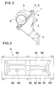
- an intake chamber 1 is dividedly cast into a first chamber 2 and a second chamber 3, and flanges 4 and 5 are formed at the end openings of these chambers 2 and 3 in such a manner as to clamp a reinforcing plate 6 between them.
- intake manifolds 7 As many intake manifolds 7 as the number of cylinders of the engine are dispersedly formed in the first chamber 2.
- An intake pipe 8 is connected to one of the ends of the second chamber 3, and intake air is supplied to this intake pipe 8 through a filter and another intake pipe, and is supplied to an intake port of an engine, not shown, from the intake manifolds 7.
- the reinforcing plate 6 is constituted in such a manner as to partition the first chamber 2a and the second chamber 3a, to mix intake air supplied from the intake pipe 8, to disperse intake air so as to unfiromly supply it to each intake manifold 7 and to reinforce the intake chamber 1 comprising the first chamber 2 and the second chamber 3 as a whole.
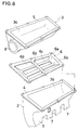
- the reinforcing plate 6 in this embodiment has a rectangular pan shape as a whole, and one of the surfaces protrudes only slightly, as shown in Figs. 3 to 5.
- An ordinary rolled steel sheet or stainless steel sheet is used for this reinforcing plate 6.
- the reinforcing plate 6 includes a frame 6a that forms an outer shape, a seal portion and a basic portion for reinforcement, a longitudinal reinforcing rib 6c and a transverse reinforcing rib 6b. These members define windows 6d between them and form a grid shape as a whole. Further, bolt holes 6e are bored in the frame 6a.
- the first chamber 2 and the second chamber 3 are assembled so that the protruding portion faces the second chamber side 2a of the first chamber 2 as shown in Fig. 6.
- the frame 6a of the reinforcing plate 6 and the other reinforcing ribs 6b and 6c are preferably intergrally constituted by stamping a sheet metal.
- the inventors of the present invention have prepared two round windows, three elongated rectangular windows for each of the right and left sides, two rectangular windows, two elliptic windows, and so forth, and have measured vibration and noise. Further, the present inventors examined the reinforcing effect, intake performance, the mixing and distribution effect of the EGR gas and the blow-by gas, the production cost, etc, and have concluded that the structure of this embodiment provides the best result.
- Fig. 7 is a graph when a four-cylinder Diesel engine having a displacement of 1,700 cc is operated at a constant rotating speed in a medium speed range.
- the abscissa represents a load and the ordinate does an EGR variations for each cylinder at this time.
- a dash line represents the EGR variations in each cylinder when the intake chamber of the embodiment described above is used under the condition that the EGR variation of each cylinder of an intake chamber without the reinforcing plate according to the prior art is 100%.
- the Diesel engine equipped with the intake chamber according to the present invention mixes intake air with the EGR gas and disperses the mixed gas while preventing the vibration. Therefore, an EGR ratio having a uniform and small variations for the four cylinders can be obtained particularly in the load range in which EGR is effected. Accordingly, this embodiment can exploit more efficiently the EGR effect than in the conventional engines, and can purify the exhaust gas.
- the intake chamber according to the present invention can provide the following effects.
Landscapes
- Engineering & Computer Science (AREA)
- Chemical & Material Sciences (AREA)
- Combustion & Propulsion (AREA)
- Mechanical Engineering (AREA)
- General Engineering & Computer Science (AREA)
- Physics & Mathematics (AREA)
- Geometry (AREA)
- Manufacturing & Machinery (AREA)
- Exhaust-Gas Circulating Devices (AREA)
- Cylinder Crankcases Of Internal Combustion Engines (AREA)
- Lubrication Details And Ventilation Of Internal Combustion Engines (AREA)
- Characterised By The Charging Evacuation (AREA)
Applications Claiming Priority (3)
| Application Number | Priority Date | Filing Date | Title |
|---|---|---|---|
| JP243415/95 | 1995-09-21 | ||
| JP24341595 | 1995-09-21 | ||
| JP24341595A JP3680371B2 (ja) | 1995-09-21 | 1995-09-21 | 吸気チヤンバー |
Publications (3)
| Publication Number | Publication Date |
|---|---|
| EP0764781A2 true EP0764781A2 (fr) | 1997-03-26 |
| EP0764781A3 EP0764781A3 (fr) | 1997-12-03 |
| EP0764781B1 EP0764781B1 (fr) | 1999-12-29 |
Family
ID=17103532
Family Applications (1)
| Application Number | Title | Priority Date | Filing Date |
|---|---|---|---|
| EP19960114588 Expired - Lifetime EP0764781B1 (fr) | 1995-09-21 | 1996-09-12 | Chambre d'admission |
Country Status (3)
| Country | Link |
|---|---|
| EP (1) | EP0764781B1 (fr) |
| JP (1) | JP3680371B2 (fr) |
| DE (1) | DE69605878T2 (fr) |
Cited By (4)
| Publication number | Priority date | Publication date | Assignee | Title |
|---|---|---|---|---|
| FR2783567A1 (fr) * | 1998-09-23 | 2000-03-24 | Renault | Collecteur d'admission pour moteur a combustion interne |
| FR2868132A1 (fr) * | 2004-03-26 | 2005-09-30 | Mann & Hummel Gmbh | Installation d'admission de moteur a combustion interne |
| ITRE20110066A1 (it) * | 2011-09-08 | 2013-03-09 | Lombardini Srl | Collettore di aspirazione dell'aria comburente per un motore a combustione interna dotato di egr |
| DE102015219629A1 (de) * | 2015-10-09 | 2017-04-13 | Röchling Automotive SE & Co. KG | Fahrzeug-Ansaugtrakt |
Families Citing this family (3)
| Publication number | Priority date | Publication date | Assignee | Title |
|---|---|---|---|---|
| DE102004009312B3 (de) * | 2004-02-26 | 2005-04-28 | Hatz Motoren | Verfahren zur Herstellung eines einteiligen Zylinderkopfs für Dieselmotoren durch Druckgießen und Druckgussform zur Verwendung in dem Verfahren |
| JP4523455B2 (ja) * | 2005-03-01 | 2010-08-11 | 本田技研工業株式会社 | 吸気チャンバ |
| JP4872926B2 (ja) * | 2008-01-15 | 2012-02-08 | トヨタ自動車株式会社 | 多気筒内燃機関の吸気系構造 |
Family Cites Families (4)
| Publication number | Priority date | Publication date | Assignee | Title |
|---|---|---|---|---|
| DE2214373A1 (de) * | 1972-03-24 | 1973-10-04 | Daimler Benz Ag | Verteiler fuer das ansaugsystem einer mehrzylindrigen kolbenbrennkraftmaschine |
| DE2702160C2 (de) * | 1977-01-20 | 1982-09-23 | Volkswagenwerk Ag, 3180 Wolfsburg | Ansaugsystem |
| JPH07122419B2 (ja) * | 1986-09-10 | 1995-12-25 | マツダ株式会社 | エンジンの吸気装置 |
| DE4403219A1 (de) * | 1994-02-03 | 1995-08-10 | Daimler Benz Ag | Als Baueinheit vorfertigbares Saugmodul für eine Mehrzylnder-Brennkraftmaschine |
-
1995
- 1995-09-21 JP JP24341595A patent/JP3680371B2/ja not_active Expired - Fee Related
-
1996
- 1996-09-12 EP EP19960114588 patent/EP0764781B1/fr not_active Expired - Lifetime
- 1996-09-12 DE DE1996605878 patent/DE69605878T2/de not_active Expired - Fee Related
Cited By (6)
| Publication number | Priority date | Publication date | Assignee | Title |
|---|---|---|---|---|
| FR2783567A1 (fr) * | 1998-09-23 | 2000-03-24 | Renault | Collecteur d'admission pour moteur a combustion interne |
| FR2868132A1 (fr) * | 2004-03-26 | 2005-09-30 | Mann & Hummel Gmbh | Installation d'admission de moteur a combustion interne |
| ITRE20110066A1 (it) * | 2011-09-08 | 2013-03-09 | Lombardini Srl | Collettore di aspirazione dell'aria comburente per un motore a combustione interna dotato di egr |
| EP2568154A1 (fr) * | 2011-09-08 | 2013-03-13 | Lombardini S.r.l. | Collecteur d'admission d'air comburant d'un moteur à combustion interne équipé d'un EGR |
| US8919315B2 (en) | 2011-09-08 | 2014-12-30 | Lombardini S.R.L. | Intake manifold of comburent air for an internal combustion engine equipped with EGR |
| DE102015219629A1 (de) * | 2015-10-09 | 2017-04-13 | Röchling Automotive SE & Co. KG | Fahrzeug-Ansaugtrakt |
Also Published As
| Publication number | Publication date |
|---|---|
| JP3680371B2 (ja) | 2005-08-10 |
| DE69605878D1 (de) | 2000-02-03 |
| EP0764781A3 (fr) | 1997-12-03 |
| JPH0988744A (ja) | 1997-03-31 |
| DE69605878T2 (de) | 2000-06-15 |
| EP0764781B1 (fr) | 1999-12-29 |
Similar Documents
| Publication | Publication Date | Title |
|---|---|---|
| JP4923036B2 (ja) | 内燃機関の排気ガス再循環装置 | |
| US4191148A (en) | Aftercooler assembly for internal combustion engine | |
| EP0764781B1 (fr) | Chambre d'admission | |
| JPH0814126A (ja) | V型エンジンの吸気装置 | |
| US6324839B1 (en) | Exhaust manifold for internal combustion engines | |
| CN113606068B (zh) | 进气歧管、进气系统和汽车 | |
| US6752113B2 (en) | Mounting arrangement for an intake manifold and a method of making same | |
| JPS61182452A (ja) | エンジンの吸気装置 | |
| JPH0565857A (ja) | インテークマニホールドの支持構造 | |
| JP2000045880A (ja) | インテークマニホールド | |
| JPH10131813A (ja) | エンジンのガス分配構造 | |
| CN210660360U (zh) | 带弯管结构的进气歧管 | |
| JPH0814127A (ja) | インテークマニホールド及び排気ガス還流用インテークマニホールド | |
| US7069894B2 (en) | Intake manifold having intake pipes linked by transverse acoustic synchronization channels with exhaust gas recirculation inlets | |
| US4930461A (en) | One-piece lost foam pattern for an intake manifold | |
| KR100729259B1 (ko) | 다기통엔진의 흡기장치 | |
| EP1580421B2 (fr) | Dispositif pour mélanger les gas d'échappement recyclés à l'air d'admission d'un moteur et procédé pour recycler les gaz d'échappement | |
| JPH10196474A (ja) | インテークマニホールド | |
| US6622687B2 (en) | Intake apparatus of multi-cylinder internal combustion engine | |
| CN222716989U (zh) | 一种发动机进气管 | |
| JPH0437254Y2 (fr) | ||
| JPH10252577A (ja) | 内燃機関のegr分配装置 | |
| JP3807129B2 (ja) | 吸気マニホールド | |
| JP3170934B2 (ja) | 2サイクルv型エンジン | |
| JPH0232859Y2 (fr) |
Legal Events
| Date | Code | Title | Description |
|---|---|---|---|
| PUAI | Public reference made under article 153(3) epc to a published international application that has entered the european phase |
Free format text: ORIGINAL CODE: 0009012 |
|
| AK | Designated contracting states |
Kind code of ref document: A2 Designated state(s): DE FR GB IT |
|
| PUAL | Search report despatched |
Free format text: ORIGINAL CODE: 0009013 |
|
| AK | Designated contracting states |
Kind code of ref document: A3 Designated state(s): DE FR GB IT |
|
| 17P | Request for examination filed |
Effective date: 19980407 |
|
| 17Q | First examination report despatched |
Effective date: 19980715 |
|
| GRAG | Despatch of communication of intention to grant |
Free format text: ORIGINAL CODE: EPIDOS AGRA |
|
| GRAG | Despatch of communication of intention to grant |
Free format text: ORIGINAL CODE: EPIDOS AGRA |
|
| GRAH | Despatch of communication of intention to grant a patent |
Free format text: ORIGINAL CODE: EPIDOS IGRA |
|
| GRAH | Despatch of communication of intention to grant a patent |
Free format text: ORIGINAL CODE: EPIDOS IGRA |
|
| GRAA | (expected) grant |
Free format text: ORIGINAL CODE: 0009210 |
|
| AK | Designated contracting states |
Kind code of ref document: B1 Designated state(s): DE FR GB IT |
|
| REF | Corresponds to: |
Ref document number: 69605878 Country of ref document: DE Date of ref document: 20000203 |
|
| ET | Fr: translation filed | ||
| ITF | It: translation for a ep patent filed | ||
| PLBE | No opposition filed within time limit |
Free format text: ORIGINAL CODE: 0009261 |
|
| STAA | Information on the status of an ep patent application or granted ep patent |
Free format text: STATUS: NO OPPOSITION FILED WITHIN TIME LIMIT |
|
| 26N | No opposition filed | ||
| REG | Reference to a national code |
Ref country code: GB Ref legal event code: IF02 |
|
| PGFP | Annual fee paid to national office [announced via postgrant information from national office to epo] |
Ref country code: DE Payment date: 20070822 Year of fee payment: 12 |
|
| PGFP | Annual fee paid to national office [announced via postgrant information from national office to epo] |
Ref country code: GB Payment date: 20070824 Year of fee payment: 12 |
|
| PGFP | Annual fee paid to national office [announced via postgrant information from national office to epo] |
Ref country code: IT Payment date: 20070820 Year of fee payment: 12 |
|
| PGFP | Annual fee paid to national office [announced via postgrant information from national office to epo] |
Ref country code: FR Payment date: 20070812 Year of fee payment: 12 |
|
| GBPC | Gb: european patent ceased through non-payment of renewal fee |
Effective date: 20080912 |
|
| REG | Reference to a national code |
Ref country code: FR Ref legal event code: ST Effective date: 20090529 |
|
| PG25 | Lapsed in a contracting state [announced via postgrant information from national office to epo] |
Ref country code: IT Free format text: LAPSE BECAUSE OF NON-PAYMENT OF DUE FEES Effective date: 20080912 Ref country code: DE Free format text: LAPSE BECAUSE OF NON-PAYMENT OF DUE FEES Effective date: 20090401 |
|
| PG25 | Lapsed in a contracting state [announced via postgrant information from national office to epo] |
Ref country code: FR Free format text: LAPSE BECAUSE OF NON-PAYMENT OF DUE FEES Effective date: 20080930 |
|
| PG25 | Lapsed in a contracting state [announced via postgrant information from national office to epo] |
Ref country code: GB Free format text: LAPSE BECAUSE OF NON-PAYMENT OF DUE FEES Effective date: 20080912 |