EP0764794B1 - Schwingungs- und stossdämpfende Einrichtung mit lagerndem Element und gelagertes Element, vereinigt mit Kabelabschnitten und stabilisierenden Blättern - Google Patents
Schwingungs- und stossdämpfende Einrichtung mit lagerndem Element und gelagertes Element, vereinigt mit Kabelabschnitten und stabilisierenden Blättern Download PDFInfo
- Publication number
- EP0764794B1 EP0764794B1 EP96401951A EP96401951A EP0764794B1 EP 0764794 B1 EP0764794 B1 EP 0764794B1 EP 96401951 A EP96401951 A EP 96401951A EP 96401951 A EP96401951 A EP 96401951A EP 0764794 B1 EP0764794 B1 EP 0764794B1
- Authority
- EP
- European Patent Office
- Prior art keywords
- cable
- support
- blades
- cable segments
- supported members
- Prior art date
- Legal status (The legal status is an assumption and is not a legal conclusion. Google has not performed a legal analysis and makes no representation as to the accuracy of the status listed.)
- Expired - Lifetime
Links
Images




Classifications
-
- F—MECHANICAL ENGINEERING; LIGHTING; HEATING; WEAPONS; BLASTING
- F16—ENGINEERING ELEMENTS AND UNITS; GENERAL MEASURES FOR PRODUCING AND MAINTAINING EFFECTIVE FUNCTIONING OF MACHINES OR INSTALLATIONS; THERMAL INSULATION IN GENERAL
- F16F—SPRINGS; SHOCK-ABSORBERS; MEANS FOR DAMPING VIBRATION
- F16F7/00—Vibration-dampers; Shock-absorbers
- F16F7/14—Vibration-dampers; Shock-absorbers of cable support type, i.e. frictionally-engaged loop-forming cables
Definitions
- the present invention relates, in general, to anti-vibration / anti-shock devices. More specifically, it concerns devices of the type comprising a carrying element and a supported element linked by a damping means.
- damping devices are used in particular for the suspension of electric or internal combustion engines or air compressors or others, but also for the protection of equipment fragile or sensitive against shock or vibration.
- FIGS 1a and 1b are, respectively, an elevational view and a sectional view transverse along line X-X of Figure 1a. It consists of a set of four stainless steel blades, substantially U-shaped, received two by two one inside the other, the internal and external blades of each set of two blades 10, 10 ', 11, 11' being respectively fixed to the blades corresponding to the other set of two, by their ends and by riveting, to form a damping device 1 of approximately elliptical shape.
- the attachment also uses attachment plates 12, 13 and 12 ', 13', respectively, covering the joint planes of the blades, and spacer plates 14 and 14 ', respectively, interposed between the blades external 10, 10 'and internal 11, 11' respectively.
- the spaces between the external blades 10, 10 'and internal 11, 11' are filled with a resin-based cushioning compound 15 epoxy.
- the bores 16 and 16 'formed in the blades and respective plates allow the attachment of the object to be worn and that of the damping device 1 on a base.
- the epoxy resin has very poor performance in temperature: around 0 ° C it is practically rigid, while around 30 ° C it is of a rather soft consistency.
- the resonant frequency of the device damper becomes highly dependent on temperature, which is unacceptable for such a device, since it seeks to wedge it of origin at a given resonant frequency for a given carried mass.
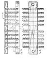
- FIGS. 2a to 2c are respectively views in partial section, in elevation and in plan of this device.
- This device 20 includes a bar 21 in which an area middle of several strands of cable 22 are anchored, while the ends free of these arms 22 are each anchored in an elongated element 26, 27.
- the elongated elements 26 and 27 are retained side by side, in a plane parallel to that of the bar 21, by means of a retaining means 28, the strands of cable 22 thus defining, on either side of the bar 21 and of the elements 26 and 27, curved cable segments 22, parallel to each other.
- the present invention aims to overcome these drawbacks.
- an anti-vibration / anti-shock device kind comprising a carrying element and a carried element arranged face to face and united by a plurality of cable segments arranged on either side of the load-bearing and carried elements, each of these cable segments being fixed to the carrier element and the element carried and extending between said elements carrier and carried along an at least partially curved cable route, device characterized in that said supporting and carried elements are further united by two opposite stabilizing blades, also fixed by their ends to the said bearing and carried elements, and located on either side of these bearing elements and worn, said stabilizing blades having a corresponding profile substantially to that of the cable tray of said cable segments.
- the present invention overcomes the disadvantages mentioned above.
- the stabilizing blades have a certain stiffness
- the diameter of the cable segments can be chosen smaller than that of the strands of prior art cable, facilitating assembly of the device shock absorber, while remaining within the dimensions of the shock absorbing devices the state of the art.
- At least one of the supporting elements and carried is a modular element comprising, on the one hand, anchoring modules individual cable segments and, on the other hand, joining means of these.
- the manufacture of the device is facilitated. Indeed, the anchoring of the cable segments on the load-bearing and carried elements can be done flat, before coming to assemble the individual anchor modules using the assembly means.
- the device occupies a small volume, facilitating its transport and storage.
- said means assembly also act as means of fixing the blades on the load-bearing and worn elements.
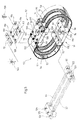
- FIGS. 3 to 6 Prior to the description, in particular in support of FIG. 3, of a first embodiment of an anti-vibration / anti-shock device in accordance with the invention, it should be observed that in FIGS. 3 to 6, certain parts of the device according to the invention have been shown in lines interrupted, to schematize the unassembled state of the devices correspondents.
- FIGS. 3 to 6 elements identical or similar have the same reference numbers.
- an anti-vibration / anti-shock device 50 comprises a carrier element 51 and a supported element 52 united by four cable segments 53, 54, 55, 56 and two stabilizing blades 57, 58 in U shape, forming damping means.
- the device is here intended to carry a mechanism generating vibrations, this mechanism being fixed on the element carried 52 by a screw (not shown) adapted to pass through the bore 59 formed in the carried element 52, while another bore 60 made in the carrier element 51 allows the fixing the device 50 to a support base.
- the supporting elements 51 and carried 52 are blocks having substantially the shape of rectangular parallelepipeds and are made of molded light alloy, such as aluminum.
- the ends of individual cable segments 53, 54, 55, 56 were anchored by molding in the carrying elements 51 and carried 52. In the present case, one of the ends of each segment has been anchored in the bearing element 51, while the other has was anchored in the worn element 52, so as to have, on either side of the carrier elements 51 and carried 52, two cable segments parallel to one another the other and having substantially a U-shape.
- these cable segments 53, 54, 55, 56 are here arranged symmetrically with respect to a median plane transverse of the device 50.
- the stabilizing blades 57, 58 are made of stainless steel and have a U-shaped profile allowing them to surround, at a distance, the U taken by the cable tray of the cable segments 53, 54, 55, 56 correspondents.
- blades 57, 58 are, moreover, fixed by screwing on the carrier elements 51 and carried 52.
- the carried element 52 is provided with two lateral recesses 61, 62, on its side facing outward, of on either side of the bore 59, each of these recesses 61, 62 comprising three threads, marked respectively 65, 66, 67 and 68, 69, 70.
- the carrier element 51 is also provided with lateral recesses 63, 64 and of threads similar to those of the carried element 52.
- Each end of the U-shaped profile of each blade 57, 58 is wedged in a lateral recess 61, 62, 63, 64 corresponding and has three communicating holes respectively with the corresponding threads used in the recesses side 61, 62, 63, 64.
- Plates 71, 72, 73, 74 are superimposed on the ends of the blades 57, 58 wedged in the lateral recesses 61, 62, 63, 64, so that their outward facing surfaces come flush with the surface facing outward of the carrier element 51 or carried 52.
- These plates are also perforated with through holes 75, 76, 77, coming from communicate with the corresponding holes and threads of the blades and load-bearing and worn elements.
- screws only three of which were represented in FIG. 3 and bear the numerical references 78, 79, 80, are screwed into the threads of the various lateral recesses 61, 62, 63, 64, passing through the corresponding holes in the ends of the blades 57, 58 and plates 71, 72, 73, 74, making it possible to fix the blades 57, 58 to the bearing elements 51 and carried 52.
- these blades 57, 58 are arranged face to face, on the side and other of the supporting elements 51 and carried 52, so as to define a form of anti-vibration / anti-shock device 50 approximately elliptical.
- FIG. 4 In Figure 4 is shown a preferred embodiment of the anti-vibration / anti-shock device 50.
- the latter is identical in all respects to anti-vibration / anti-shock device 50 of FIG. 3, apart from the carried element 52 which is, here, a modular element. It will therefore be described below only the characteristics relating to this modular element 52.
- This modular element 52 comprises, first of all, two modules individual anchoring 91, 92 of the ends of the cable segments 53, 54, 55, 56. These modules 91, 92 are also produced by molding.
- one of the anchor modules 91, 92 is a male element 91 intended to be inserted in the other anchoring module 92 constituting a female element.
- the male element 91 for this purpose comprises two fingers 93, 94 which, in the assembled state of the modular element 52 engages in two complementary recesses 95, 96 made in the female element 92.
- the modular element also comprises means assembly of the individual anchor modules 91, 92.
- these assembly means consist of two pins, only one of which has been shown in Figure 4 and carries the reference numeral 97.
- the fingers 93 and 94 of the element male 91 are each provided with a bore 98, 99 communicating, in the state assembled male 91 and female 92 elements at both ends with receiving holes made on either side of the recesses 95, 96 in the female element 92, only three of these receiving holes being visible on the Figure 4 and bearing the reference numerals 100, 101, 102.
- the fingers 93 and 94 are shaped so as to surround, in the assembled state, male 91 and female 92 elements, the bore 59 described in more detail in support of FIG. 3 and that the offset lateral 71 is here produced in the assembled state of male 91 and female 92 elements, by an overlap of the part of the female element 92 facing the exterior, above the male element 91.
- the molding of the carrier elements 51 and carried 52 as well as the anchoring of the ends of the cable segments 53, 54, 55, 56, on these elements can be made flat, before we come to assemble the modular element, then fix the U-shaped stabilizing blades 57, 58.
- the manufacturing this anti-vibration / shock-absorbing device 50 is thus somewhat easier than in the case of the first embodiment described in the support of Figure 3, where it is necessary to have spacers between the molds of the supporting elements 51 and carried 52.
- the elements carrier 51 and carrier 52 are now both modular elements.
- these modular elements 51, 52 comprise, on the one hand, individual anchoring modules 110, 111, 112, 113 having in section a L-shaped.
- the modular elements 51, 52 comprise, on the other hand, means for assembling individual anchor modules 110, 111, 112, 113 to each other, in this case consisting of attachment plates 114, 114 'in which are bores 59 and 60 respectively, but also three screw passage bores on each side holes 59 and 60.
- Screws 127, 128, 129, 130, 131, 132 passing through bores 115, 116, 117, 118, 119, 120 allow, by screwing in the threads 121, 122, 123, 124, 125, 126, to realize the assembly of the individual anchor modules 110 and 111 and so similar, anchor modules 112 and 113.
- the stabilizing blades 57, 58 are, for their part, fixed by screwing, similar to the previous embodiment, on the seconds branches of the L formed by the individual anchor modules 110, 111, 112, 113: only one of the screws used for this purpose is referenced in FIG. 5 and bears the reference numeral 145.
- Turntables 71, 72, 73, 74 are here also implemented, the lateral recesses being carried out thanks to the thickness of the attachment plates 114, 114 '.
- the individual anchoring means 110, 111, 112, 113 as well as the attachment plates 114, 114 ′ are here also produced by molding.
- the elements carrier 51 and carrier 52 are again made in modular form, but not by molding.
- Each of the anchoring modules 140, 141, 142, 143 is made up two bars, of which only those of module 142 have been referenced on the Figure 6 and bear the references 150, 151, between which the ends of the corresponding cable segments 53, 54, 55, 56. To this end, these bars 150, 151 are each provided with grooves substantially semicircular receiving ends of cable segments 53, 54, 55, 56 correspondents.
- the bars of the other anchor modules 140, 141 and 143 are of course of identical structure to those referenced 150 and 151.
- the different bolts also pass through holes and bores (not referenced in figure 6) made in the blades stabilizers 57, 57 ', 58, 58' as well as in the bars 150, 151, allowing thus, not only to assemble the bars to each other, the individual anchor modules 140, 141, 142, 143 to each other, but also to fix the stabilizing blades 57, 57 ', 58, 58' to the elements modular carrier 51 and carried 52.
- the stabilizing blades internal 57 ', 58' are fixed on the internal surface of the bars corresponding anchor modules 140, 141, 142, 143, while the external stabilizing blades 57, 58 are inserted between the anchoring modules 140, 141, 142, 143 and the attachment plates 160, 161.
- the latter is free to provide on either side of the carrier elements 51 and carried 52, more than two parallel cable segments, or one more cable segment per side.
- those skilled in the art may plan to have side by side or even superimposed on several stabilizing blades, such as those marked 57, 58 on the one hand, and 57 ', 58' on the other hand, in Figures 3 to 6.
- the ends of the cable segments 53, 54, 55, 56 may also be fixed on the supporting elements 51 and carried 52 by others means known to those skilled in the art, such as crimping, bonding, etc.
- the steel stabilizing blades can also be replaced by stabilizer blades in composite material.
- stabilizing blades 57, 58 instead of being placed at the outside of the cable segments as is the case in the modes of realization described in support of figures 3 to 5, could be placed inside only segments of cable, similarly to the arrangement of the blades stabilizers 57 ′, 58 ′ of the embodiment described in support of FIG. 6.
Landscapes
- Engineering & Computer Science (AREA)
- General Engineering & Computer Science (AREA)
- Mechanical Engineering (AREA)
- Bridges Or Land Bridges (AREA)
- Vibration Prevention Devices (AREA)
- Vehicle Body Suspensions (AREA)
Claims (9)
- Schwingungs- und stossdämpfende Einrichtung mit lagerndem Element (51) und gelagertem Element (52), welche einander gegenüberliegend angeordnet und durch eine Vielzahl von Seilabschnitten (53-56) vereinigt sind, welche beiderseits des lagernden Elements und des gelagerten Elements angeordnet sind, wobei jeder dieser Seilabschnitte am lagernden Element und am gelagerten Element befestigt ist und sich zwischen dem lagernden und dem gelagerten Element gemäß einem Seilverlauf erstreckt, der zumindest teilweise gekrümmt ist, dadurch gekennzeichnet, dass das lagernde und das gelagerte Element außerdem durch mindestens zwei gegenüberliegende stabilisierende Blätter (57,58) vereinigt sind, welche ebenfalls an ihren Enden am lagernden Element und am gelagerten Element befestigt sind und welche beiderseits des lagernden Elements des gelagerten Elements gelegen sind, wobei die stabilisierenden Blätter (57,58) ein Profil aufweisen, das im wesentlichen demjenigen dem Seilverlauf der Seilabschnitte entspricht.
- Vorrichtung nach Anspruch 1, dadurch gekennzeichnet, dass mindestens eines des lagernden Elements (51) und des gelagerten Elements (52) ein Modulelement ist, das einerseits individuelle Verankerungsmodule der Seilabschnitte und andererseits Mittel zum Zusammenbau derselben aufweist.
- Vorrichtung nach Anspruch 2, dadurch gekennzeichnet, dass die Mittel zum Zusammenbau auch die Aufgabe von Mitteln zur Befestigung der Blätter (57,58) auf dem lagernden und dem gelagerten Element erfüllen.
- Vorrichtung nach einem der Ansprüche 1 bis 3, dadurch gekennzeichnet, dass die Blätter und die Seilverläufe im wesentlichen die Form eines U aufweisen.
- Vorrichtung nach einem der Ansprüche 1 bis 4, dadurch gekennzeichnet, dass zwei Seilabschnitte, die zueinander parallel sind, beiderseits des lagernden Elements und des gelagerten Elements vorhanden sind.
- Vorrichtung nach einem der Ansprüche 2 bis 5, dadurch gekennzeichnet, dass eines des lagernden Elements und des gelagerten Elements ein Modulelement ist und dass die beiderseits des lagernden Elements und des gelagerten Elements angeordneten Seilabschnitte paarweise Teil desselben Seilstranges sind, wobei die freien Enden dieses Seilstranges auf den individuellen Verankerungsmodulen verankert sind.
- Vorrichtung nach einem der Ansprüche 1 bis 5, dadurch gekennzeichnet, dass die Seilabschnitte von individuellen Seilsträngen gebildet sind.
- Vorrichtung nach einem der Ansprüche 1 bis 7, dadurch gekennzeichnet, dass sie ein Spiel aus zwei stabilisierenden Blättern (57,57',58,58') in Form eines U beiderseits lagernden Elements und des gelagerten Elements aufweist, wobei die beiden Blätter jeweils ineinander aufgenommen sind, wobei sie die entsprechenden Seilabschnitte, die einen ebenfalls U-förmigen Seilverlauf aufweisen, umrahmen.
- Vorrichtung nach einem der Ansprüche 1 bis 8, dadurch gekennzeichnet, dass das lagernde Element und das gelagerte Element durch Guss hergestellt sind, wobei die Seilabschnitte in diesen letzteren verankert sind.
Applications Claiming Priority (2)
| Application Number | Priority Date | Filing Date | Title |
|---|---|---|---|
| FR9511056 | 1995-09-20 | ||
| FR9511056A FR2738888B1 (fr) | 1995-09-20 | 1995-09-20 | Dispositif antivibrations/antichocs du genre comportant un element porteur et un element porte unis par des segments de cable et des lames stabilisatrices |
Publications (2)
| Publication Number | Publication Date |
|---|---|
| EP0764794A1 EP0764794A1 (de) | 1997-03-26 |
| EP0764794B1 true EP0764794B1 (de) | 2000-07-26 |
Family
ID=9482768
Family Applications (1)
| Application Number | Title | Priority Date | Filing Date |
|---|---|---|---|
| EP96401951A Expired - Lifetime EP0764794B1 (de) | 1995-09-20 | 1996-09-12 | Schwingungs- und stossdämpfende Einrichtung mit lagerndem Element und gelagertes Element, vereinigt mit Kabelabschnitten und stabilisierenden Blättern |
Country Status (6)
| Country | Link |
|---|---|
| US (1) | US5897093A (de) |
| EP (1) | EP0764794B1 (de) |
| CA (1) | CA2185615A1 (de) |
| DE (1) | DE69609467D1 (de) |
| ES (1) | ES2148701T3 (de) |
| FR (1) | FR2738888B1 (de) |
Families Citing this family (52)
| Publication number | Priority date | Publication date | Assignee | Title |
|---|---|---|---|---|
| JP3595439B2 (ja) * | 1997-12-17 | 2004-12-02 | 核燃料サイクル開発機構 | 圧縮・引張荷重型鉛ダンパ |
| DE59909482D1 (de) * | 1999-11-04 | 2004-06-17 | Deuta Werke Gmbh | Vorrichtung zur gedämpften Lagerung eines Objekts |
| ES2246208T3 (es) * | 1999-11-05 | 2006-02-16 | Sebert Schwingungstechnik Gmbh | Disposicion de amortiguacion. |
| US6299150B1 (en) * | 2000-02-01 | 2001-10-09 | Lockheed Martin Corporation | Composite spring mount shock absorber |
| US6244579B1 (en) * | 2000-02-02 | 2001-06-12 | Enidine, Incorporated | Light press manufactured (LPM) wire rope isolator and method of manufacture |
| US6406011B1 (en) * | 2000-02-02 | 2002-06-18 | Enidine Incorporated | Wire rope isolator with pinned bar and method for making same |
| US6290217B1 (en) * | 2000-03-29 | 2001-09-18 | Enidine Incorporated | Asymmetric wire rope isolator |
| US6695296B1 (en) * | 2000-11-09 | 2004-02-24 | Northrop Grumman Corporation | Shock and vibration isolation mount with variable thickness support section |
| RU2200884C2 (ru) * | 2001-01-09 | 2003-03-20 | Закрытое акционерное общество Научно-производственный центр информационных и транспортных систем | Виброизолятор |
| US6478173B2 (en) * | 2001-02-13 | 2002-11-12 | Miner Enterprises, Inc. | Railroad car draft gear having a long travel |
| RU2220341C2 (ru) * | 2001-04-12 | 2003-12-27 | Самарская государственная академия путей сообщения | Упругодемпферная опора |
| ATE317951T1 (de) | 2001-08-08 | 2006-03-15 | Isic As | Schwingungsdämpfer zur dämpfung von schwingungen mit niedrigen frequenzen |
| RU2237204C2 (ru) * | 2002-06-24 | 2004-09-27 | Самарская государственная академия путей сообщения | Упругодемпферная опора |
| ES2233168B1 (es) * | 2003-02-21 | 2006-07-16 | Jose Gurri Molins | Elemento de absorcion y aislamiento de componentes bi-o-tri-dimensionales de movimiento , aplicable a maquinas, dispositivos e implementos mecanicos. |
| RU2249736C1 (ru) * | 2003-10-14 | 2005-04-10 | Закрытое акционерное общество Научно-производственный центр информационных и транспортных систем (НПЦ ИНФОТРАНС) | Кольцевой пластинчатый виброизолятор |
| RU2269700C1 (ru) * | 2004-05-31 | 2006-02-10 | Олег Савельевич Кочетов | Виброизолятор рессорного типа |
| RU2269702C1 (ru) * | 2004-05-31 | 2006-02-10 | Олег Савельевич Кочетов | Виброизолятор для ткацких станков |
| RU2276295C2 (ru) * | 2004-05-31 | 2006-05-10 | Олег Савельевич Кочетов | Пространственный рессорный виброизолятор |
| RU2267038C1 (ru) * | 2004-05-31 | 2005-12-27 | Кочетов Олег Савельевич | Виброизолятор рессорный |
| RU2267037C1 (ru) * | 2004-05-31 | 2005-12-27 | Кочетов Олег Савельевич | Виброизолирующая система для ткацких станков |
| FR2872784B1 (fr) * | 2004-07-09 | 2007-10-12 | Eurocopter France | Systeme de suspension d'un moteur d'aeronef a voilure tournante |
| US20060086874A1 (en) * | 2004-10-26 | 2006-04-27 | Somfy Systems, Inc. | Anti-vibration bracket for tubular motor |
| RU2285161C1 (ru) * | 2005-02-25 | 2006-10-10 | Открытое акционерное общество "Концерн "Моринформсистема -Агат" (ОАО "Концерн "Моринсис - Агат") | Витой спиральный виброизолятор |
| CN100411895C (zh) * | 2005-09-15 | 2008-08-20 | 合肥工业大学 | 钢缆弹簧式汽车后桥减振器 |
| RU2298119C1 (ru) * | 2005-09-19 | 2007-04-27 | Олег Савельевич Кочетов | Способ виброизоляции и виброизолятор с квазинулевой жесткостью |
| RU2299370C1 (ru) * | 2005-09-19 | 2007-05-20 | Олег Савельевич Кочетов | Виброизолятор равночастотный рессорного типа |
| RU2293231C1 (ru) * | 2005-09-19 | 2007-02-10 | Олег Савельевич Кочетов | Виброизолятор рессорный |
| RU2295071C1 (ru) * | 2005-09-19 | 2007-03-10 | Олег Савельевич Кочетов | Виброизолятор с плоскими пружинами |
| RU2295072C1 (ru) * | 2005-09-19 | 2007-03-10 | Олег Савельевич Кочетов | Виброизолятор с листовыми пружинами |
| RU2301921C1 (ru) * | 2005-10-03 | 2007-06-27 | Олег Савельевич Кочетов | Резиновый виброизолятор для оборудования |
| RU2301917C1 (ru) * | 2005-10-03 | 2007-06-27 | Олег Савельевич Кочетов | Резиновый виброизолятор для опоры двигателя |
| TWI261095B (en) * | 2005-11-18 | 2006-09-01 | Ind Tech Res Inst | Steel wire vibration-isolator |
| NL2000095C2 (nl) | 2006-06-09 | 2007-12-11 | Loggers Rubbertech | Veerinrichting met veerorganen. |
| KR100830752B1 (ko) * | 2007-04-19 | 2008-05-19 | 한국철도공사 | 차량용 스크린 장치 |
| RU2370687C1 (ru) * | 2008-04-01 | 2009-10-20 | Государственное образовательное учреждение высшего профессионального образования Военно-морская академия имени Адмирала Флота Советского Союза Н.Г. КУЗНЕЦОВА | Пружинный виброизолятор с демпфирующим элементом |
| US8783518B2 (en) | 2008-12-29 | 2014-07-22 | Otic Pharma Ltd. | Multiple-metered self-cleaning dispenser |
| DE112010000809T5 (de) | 2009-01-21 | 2013-06-20 | Rafael Advanced Defense Systems Ltd. | Dämpfungsaufhängung mit der Möglichkeit zum Heben für ein Zusatz-Bewehrungssystem |
| KR20100111334A (ko) * | 2009-04-07 | 2010-10-15 | 하동석 | 동작가이드가 구비된 와이어 쇽 마운트 및 이 와이어 쇽 마운트가 부착되어 개선된 충격흡수능을 가지는 물품 |
| RU2403466C1 (ru) * | 2009-05-28 | 2010-11-10 | Государственное образовательное учреждение высшего профессионального образования "Санкт-Петербургский государственный морской технический университет" | Виброизолирующее устройство |
| GB201010419D0 (en) * | 2010-06-22 | 2010-08-04 | Secr Defence | Flexible bracket for vehicle armour |
| FR2975074B1 (fr) * | 2011-05-11 | 2013-06-21 | Dcns | Navire du type comportant au moins un puits de reception d'au moins un conteneur de lancement de missile |
| DE102014102330A1 (de) * | 2014-02-24 | 2015-08-27 | ThyssenKrupp Federn und Stabilisatoren GmbH | Tragfedereinheit für ein Fahrzeugfahrwerk |
| US10005506B2 (en) | 2015-02-27 | 2018-06-26 | Great Lakes Sound & Vibration, Inc. | Suspension arrangements for vehicles |
| US9788446B1 (en) * | 2015-03-27 | 2017-10-10 | Paul H. Townsend | Mobile vibration isolation device |
| RU179070U1 (ru) * | 2017-03-23 | 2018-04-25 | Общество с ограниченной ответственностью "Технические системы-сервис, качество и надежность" | Виброизолятор |
| EP3609735B1 (de) | 2017-04-13 | 2022-05-18 | Rheinmetall Protection Systems GmbH | Stossabsorbierender sitz mit boden- oder deckenmontierten dämpfungsgliedern |
| RU2649484C1 (ru) * | 2017-04-18 | 2018-04-03 | Олег Савельевич Кочетов | Виброизолирующая система для станка |
| US10570984B1 (en) * | 2017-06-28 | 2020-02-25 | United Launch Alliance, L.L.C. | Asymmetrically-shaped isolator |
| RU184019U1 (ru) * | 2018-06-19 | 2018-10-11 | Общество с ограниченной ответственностью "Технические системы-сервис, качество и надежность" | Устройство стабилизации ветвей троса виброизолятора |
| US11572929B2 (en) | 2020-04-16 | 2023-02-07 | Raytheon Company | Vibration isolator and method of assembly using flex circuits |
| CN113251101A (zh) * | 2021-05-13 | 2021-08-13 | 哈尔滨工业大学(深圳) | 椭圆环隔振器 |
| US12435769B2 (en) * | 2023-06-13 | 2025-10-07 | METAseismic, Inc. | Shape-morphing apparatus for shock and vibration protection |
Family Cites Families (16)
| Publication number | Priority date | Publication date | Assignee | Title |
|---|---|---|---|---|
| FR358146A (fr) * | 1905-04-28 | 1906-01-29 | Alby Carbidfabriks Aktiebolag | Procédé de production de composés ou combinaisons entre l'acétylène et le chlore, et produits ainsi obtenus |
| FR612932A (fr) * | 1926-03-18 | 1926-11-04 | Procédé d'amélioration des mortiers d'enduit | |
| US3074681A (en) * | 1959-11-27 | 1963-01-22 | Kerley Engineering Inc | Protective enclosure shock and vibration type isolator mount |
| DE1750751A1 (de) * | 1968-05-31 | 1971-03-11 | Pelat Roger Patrice | Schwingungsdaempfendes Lager |
| US4190227A (en) * | 1976-07-22 | 1980-02-26 | Aeroflex Laboratories, Inc. | Vibration isolator and method for manufacturing same |
| IT1171151B (it) * | 1983-05-05 | 1987-06-10 | Palmiro Lantero | Supporto ammortizzatore a cavo conreazioni indipendenti alle sollecitazioni verticali ed orizzontali |
| JPS62237135A (ja) * | 1986-04-07 | 1987-10-17 | Mitsubishi Electric Corp | 防振装置 |
| FR2603959B1 (fr) * | 1986-09-12 | 1992-07-24 | Intertechnique Sa | Dispositif amortisseur de chocs et de vibrations |
| US4783038A (en) * | 1987-07-07 | 1988-11-08 | Aeroflex International Incorporated | Isolator apparatus |
| DE3908474A1 (de) * | 1988-07-22 | 1990-01-25 | Metzeler Gmbh | Ringfoermiger federkoerper aus faserverbundwerkstoffen |
| FR2636111B1 (fr) * | 1988-09-05 | 1990-11-16 | Vibrachoc Sa | Dispositif amortisseur de chocs et de vibrations |
| US5149066A (en) * | 1991-02-11 | 1992-09-22 | Aeroflex International Incorporated | Isolator with improved symmetrical response to shock and vibration forces |
| US5169110A (en) * | 1991-07-18 | 1992-12-08 | Aeroflex International Incorporated | Force-damping energy-removing isolator |
| FR2689196B1 (fr) * | 1992-03-31 | 1995-08-04 | Hutchinson | Dispositif de filtrage des vibrations et systeme de fixation d'une charge sur un support comportant une pluralite de tels dispositifs. |
| FR2695696B1 (fr) * | 1992-09-17 | 1994-10-21 | Vibrachoc Sa | Système de suspension amortie coussin métallique et organe de suspension amortisseur pour un tel système. |
| FR2702020B1 (fr) * | 1993-02-22 | 1995-05-24 | Socitec | Dispositif antivibratoire/antichocs et procédé de fabrication d'un tel dispositif. |
-
1995
- 1995-09-20 FR FR9511056A patent/FR2738888B1/fr not_active Expired - Lifetime
-
1996
- 1996-09-12 ES ES96401951T patent/ES2148701T3/es not_active Expired - Lifetime
- 1996-09-12 DE DE69609467T patent/DE69609467D1/de not_active Expired - Lifetime
- 1996-09-12 EP EP96401951A patent/EP0764794B1/de not_active Expired - Lifetime
- 1996-09-16 CA CA002185615A patent/CA2185615A1/fr not_active Abandoned
- 1996-09-17 US US08/714,900 patent/US5897093A/en not_active Expired - Lifetime
Also Published As
| Publication number | Publication date |
|---|---|
| DE69609467D1 (de) | 2000-08-31 |
| US5897093A (en) | 1999-04-27 |
| EP0764794A1 (de) | 1997-03-26 |
| CA2185615A1 (fr) | 1997-03-21 |
| FR2738888A1 (fr) | 1997-03-21 |
| ES2148701T3 (es) | 2000-10-16 |
| FR2738888B1 (fr) | 1998-12-04 |
Similar Documents
| Publication | Publication Date | Title |
|---|---|---|
| EP0764794B1 (de) | Schwingungs- und stossdämpfende Einrichtung mit lagerndem Element und gelagertes Element, vereinigt mit Kabelabschnitten und stabilisierenden Blättern | |
| EP0296974A1 (de) | Elastische Lager | |
| WO2000039401A1 (fr) | Dispositif et procede de fixation entre un element de construction et un cable de structure | |
| FR2549795A1 (fr) | Chassis pour vehicule de petites dimensions | |
| CA2660492A1 (fr) | Support pour fixer des cables electriques sur une structure | |
| WO1998004780A1 (fr) | Dispositif pour amortir les vibrations d'un cable | |
| EP0509918B1 (de) | Elastische Vorrichtung zur Aufhängung einer schwingenden Struktur gegenüber einer steifen Struktur | |
| WO2005047810A1 (fr) | Piece structurale composite a rupture pyrotechnique detonante | |
| EP0666432B1 (de) | Stoss- und schwingungsdämpfende Klemme | |
| EP1932758B1 (de) | Absorbierende Verkleidung | |
| FR2702020A1 (fr) | Dispositif antivibratoire/antichocs et procédé de fabrication d'un tel dispositif. | |
| EP4179736A1 (de) | Elektrodynamischer wandler | |
| EP0636810A1 (de) | Verbesserung an den Gegenschwingungslagern von Hubschrauberrotorflügeln, und Hubschrauberrotor mit solchen Lagern | |
| CA2398553C (fr) | Procede d'assemblage optimise de deux pieces sensiblement planes | |
| EP0726084A1 (de) | Schutzvorrichtung eines rohrförmigen Elementes und derart hergestelltes Element | |
| FR3013684A1 (fr) | Structure porteuse de satellite comportant un dispositif de liaison amortissante | |
| WO1999059865A1 (fr) | Cadre de bicyclette, son procédé de fabrication et profile servant a la fabrication d'un tel cadre de bicyclette | |
| FR3058326A1 (fr) | Dispositif d'extremite inferieure d'un baton de sport | |
| EP2861872B1 (de) | Stammaufnahmeelement und zugehöriges empfangselement zur anordnung zweier teile aus polymermaterial und zugehörige anordnung | |
| EP2213339B1 (de) | Ski, der eine Schwingungsdämpfungseinrichtung umfasst | |
| EP2325075A1 (de) | Lenkstange mit Dämpfungsvorrichtung | |
| EP0028952B1 (de) | Möbelstruktur mit geräuscharmer Zusammensetzung | |
| FR2545438A1 (fr) | Procede d'assemblage de flotteurs, moyens pour la mise en oeuvre du procede, et engin flottant ainsi assemble | |
| FR3081946A1 (fr) | Ensemble de liaison comportant une piece de liaison et au moins deux pieces d'appui | |
| EP1854693A1 (de) | Seitliche Schutzvorrichtung für Transportmittel und Transportmittel, das sie umfasst |
Legal Events
| Date | Code | Title | Description |
|---|---|---|---|
| PUAI | Public reference made under article 153(3) epc to a published international application that has entered the european phase |
Free format text: ORIGINAL CODE: 0009012 |
|
| AK | Designated contracting states |
Kind code of ref document: A1 Designated state(s): BE DE ES FR GB IT NL |
|
| 17P | Request for examination filed |
Effective date: 19970826 |
|
| GRAG | Despatch of communication of intention to grant |
Free format text: ORIGINAL CODE: EPIDOS AGRA |
|
| 17Q | First examination report despatched |
Effective date: 19990924 |
|
| GRAG | Despatch of communication of intention to grant |
Free format text: ORIGINAL CODE: EPIDOS AGRA |
|
| GRAG | Despatch of communication of intention to grant |
Free format text: ORIGINAL CODE: EPIDOS AGRA |
|
| GRAH | Despatch of communication of intention to grant a patent |
Free format text: ORIGINAL CODE: EPIDOS IGRA |
|
| RTI1 | Title (correction) |
Free format text: VIBRATION AND SHOCK DAMPING DEVICE COMPRISING A CARRIER ELEMENT AND A CARRIED ELEMENT, CONNECTED BY CABLE SEGMENTS AND STABILISING LEAF SPRINGS |
|
| GRAH | Despatch of communication of intention to grant a patent |
Free format text: ORIGINAL CODE: EPIDOS IGRA |
|
| GRAA | (expected) grant |
Free format text: ORIGINAL CODE: 0009210 |
|
| AK | Designated contracting states |
Kind code of ref document: B1 Designated state(s): BE DE ES FR GB IT NL |
|
| PG25 | Lapsed in a contracting state [announced via postgrant information from national office to epo] |
Ref country code: IT Free format text: LAPSE BECAUSE OF FAILURE TO SUBMIT A TRANSLATION OF THE DESCRIPTION OR TO PAY THE FEE WITHIN THE PRESCRIBED TIME-LIMIT;WARNING: LAPSES OF ITALIAN PATENTS WITH EFFECTIVE DATE BEFORE 2007 MAY HAVE OCCURRED AT ANY TIME BEFORE 2007. THE CORRECT EFFECTIVE DATE MAY BE DIFFERENT FROM THE ONE RECORDED. Effective date: 20000726 |
|
| GBT | Gb: translation of ep patent filed (gb section 77(6)(a)/1977) |
Effective date: 20000726 |
|
| REF | Corresponds to: |
Ref document number: 69609467 Country of ref document: DE Date of ref document: 20000831 |
|
| REG | Reference to a national code |
Ref country code: ES Ref legal event code: FG2A Ref document number: 2148701 Country of ref document: ES Kind code of ref document: T3 |
|
| PG25 | Lapsed in a contracting state [announced via postgrant information from national office to epo] |
Ref country code: DE Free format text: LAPSE BECAUSE OF FAILURE TO SUBMIT A TRANSLATION OF THE DESCRIPTION OR TO PAY THE FEE WITHIN THE PRESCRIBED TIME-LIMIT Effective date: 20001027 |
|
| PLBE | No opposition filed within time limit |
Free format text: ORIGINAL CODE: 0009261 |
|
| STAA | Information on the status of an ep patent application or granted ep patent |
Free format text: STATUS: NO OPPOSITION FILED WITHIN TIME LIMIT |
|
| 26N | No opposition filed | ||
| REG | Reference to a national code |
Ref country code: GB Ref legal event code: IF02 |
|
| REG | Reference to a national code |
Ref country code: FR Ref legal event code: PLFP Year of fee payment: 20 |
|
| PGFP | Annual fee paid to national office [announced via postgrant information from national office to epo] |
Ref country code: NL Payment date: 20150813 Year of fee payment: 20 |
|
| PGFP | Annual fee paid to national office [announced via postgrant information from national office to epo] |
Ref country code: ES Payment date: 20150928 Year of fee payment: 20 Ref country code: GB Payment date: 20150817 Year of fee payment: 20 |
|
| PGFP | Annual fee paid to national office [announced via postgrant information from national office to epo] |
Ref country code: FR Payment date: 20150729 Year of fee payment: 20 |
|
| PGFP | Annual fee paid to national office [announced via postgrant information from national office to epo] |
Ref country code: BE Payment date: 20150930 Year of fee payment: 20 |
|
| REG | Reference to a national code |
Ref country code: NL Ref legal event code: MK Effective date: 20160911 |
|
| REG | Reference to a national code |
Ref country code: GB Ref legal event code: PE20 Expiry date: 20160911 |
|
| PG25 | Lapsed in a contracting state [announced via postgrant information from national office to epo] |
Ref country code: GB Free format text: LAPSE BECAUSE OF EXPIRATION OF PROTECTION Effective date: 20160911 |
|
| REG | Reference to a national code |
Ref country code: ES Ref legal event code: FD2A Effective date: 20161227 |
|
| PG25 | Lapsed in a contracting state [announced via postgrant information from national office to epo] |
Ref country code: ES Free format text: LAPSE BECAUSE OF EXPIRATION OF PROTECTION Effective date: 20160913 |