EP0764882B1 - Réceptacle pour cassette de film - Google Patents
Réceptacle pour cassette de film Download PDFInfo
- Publication number
- EP0764882B1 EP0764882B1 EP96306512A EP96306512A EP0764882B1 EP 0764882 B1 EP0764882 B1 EP 0764882B1 EP 96306512 A EP96306512 A EP 96306512A EP 96306512 A EP96306512 A EP 96306512A EP 0764882 B1 EP0764882 B1 EP 0764882B1
- Authority
- EP
- European Patent Office
- Prior art keywords
- film
- cartridge
- cartridge case
- film cartridge
- Prior art date
- Legal status (The legal status is an assumption and is not a legal conclusion. Google has not performed a legal analysis and makes no representation as to the accuracy of the status listed.)
- Expired - Lifetime
Links
Images





Classifications
-
- G—PHYSICS
- G03—PHOTOGRAPHY; CINEMATOGRAPHY; ANALOGOUS TECHNIQUES USING WAVES OTHER THAN OPTICAL WAVES; ELECTROGRAPHY; HOLOGRAPHY
- G03D—APPARATUS FOR PROCESSING EXPOSED PHOTOGRAPHIC MATERIALS; ACCESSORIES THEREFOR
- G03D3/00—Liquid processing apparatus involving immersion; Washing apparatus involving immersion
-
- G—PHYSICS
- G03—PHOTOGRAPHY; CINEMATOGRAPHY; ANALOGOUS TECHNIQUES USING WAVES OTHER THAN OPTICAL WAVES; ELECTROGRAPHY; HOLOGRAPHY
- G03D—APPARATUS FOR PROCESSING EXPOSED PHOTOGRAPHIC MATERIALS; ACCESSORIES THEREFOR
- G03D13/00—Processing apparatus or accessories therefor, not covered by groups G11B3/00 - G11B11/00
- G03D13/003—Film feed or extraction in development apparatus
Definitions
- the present invention relates to an improved film cartridge case for use with a photographic film development processor machine for developing undeveloped films or more specifically, performing a series of development, fixing, drying, and other relevant processes.
- APS advanced photo system
- a group of such new type film cartridges 90 are accommodated in a cartridge case 91 which has a tubular shape similar to that of the known film cartridge case.
- the film cartridges 90 are inserted one by one into the cartridge case 91 by dropping from above through an opening 92 of the case 91 (Fig. 15).
- An automatic film development processor machine of the type was invented by us, the applicant of this specification, as disclosed in JP-A-7 281 386 (1985), in which a group of film cartridges are placed in a cartridge case of a box or drum shape and when required, they are picked out one by one. This is followed by unloading a sheet of undeveloped film from its film cartridge and joining it with a film leader for guiding the undeveloped film sheet throughout the development process including development, fixing, and drying steps. After the development process is completed, the developed film sheet is loaded back to its film cartridge.
- the film cartridges As the film cartridges are picked out one by one, they have to be correctly positioned for joining with the film leaders and thus require a positioning means, thus contributing to no simplicity of the entire arrangement and increasing the overall size of the processor machine.
- a film cartridge case according to the present invention, is defined in claim 1.
- the film cartridge case may be characterized in that the cartridge pocket has a resilient holding projection provided on a side of an inner wall thereof for fitting resiliently into the center bore of a spool of the film cartridge thus to hold the film cartridge.
- a group of film cartridges loaded with undeveloped films comprising holding means for detachably holding the film cartridges in their respective cartridge pockets, a conveyor device arranged to be conveyed by a cartridge conveying means, and operating means for loading and unloading sheets of the film to and from their respective film cartridges installed in the cartridge pockets.
- the embodiment of the film cartridge case may be characterized in that the holding means comprises a holding projection provided on one side of the inner wall of the cartridge pocket for pressing the film cartridge inwardly by the action of its resiliency to detachably hold and position the same in the cartridge pocket.
- the film cartridge case may be characterized in that while the film cartridge to be placed in the cartridge pocket of the film cartridge case includes a cover thereof arranged to open and close a film outlet in light shielding relationship, the cartridge pocket has an insertion aperture therein through which a cover actuator is inserted for driving the cover to be opened and closed and a through center hole therein through which a spool actuator is inserted for rotating the spool to perform the loading and unloading of the film sheet to and from its film cartridge.
- the film cartridge case may be characterized in that conveyor device comprises an engaging element for engagement with the cartridge conveying means and positioning elements for positioning the cartridge pockets of the cartridge case, and the positioning of the cartridge pockets is detected through detector elements provided in the film cartridge case.
- the film cartridge case may further comprise supporting flanges provided on both side edges thereof.
- a film cartridge case 2 of this embodiment is designed for carrying therein a group of film cartridges 3 loaded with undeveloped films to continuously feed a development unit 10 of an automatic film development processor machine 1 and, as shown in Figs. 1 and 2, includes a rack (conveyed means) 27 provided on a center of a case body 2A thereof and two rows of cartridge pockets 25 (each row having five pockets in the embodiment) located on both, left and right, sides of the rack 27.
- a number of sensor slits 31 are provided in one side edge of the case body 2A of the cartridge case 2 corresponding to the row of the cartridge pockets 25.
- a film cartridge 3 of a type shown in Fig. 3 will now be explained.
- the film cartridge 3 includes a spool 16 rotatably mounted in a casing 15 thereof and a film outlet 17 provided therein for loading and unloading a sheet of film 5 on the spool 16.
- a disk 3B is mounted to one end of the spool 16 and has a barcode 3A printed thereon.
- the other end of the spool 16 is arranged for connection with a spool rotating shaft (not shown) mounted in the automatic film development processor machine and actuated by the same for loading and unloading of the film sheet 5.
- the casing 15 has two center holes 20 provided in both sides thereof and a barcode readout window 3C provided in one of the two sides thereof.
- the barcode readout window 3C is a notch in the outer edge of one side of the casing 15 which defines a step 3D around it.
- the barcode 3A represents an ISO number of sensitivity and can be read by an optical reader (not shown) while the disk 3B being rotated with the spool 16.
- the cartridge pocket 25 of the film cartridge case 2 will be explained in more details.
- the cartridge pocket 25 is designed for holding the film cartridge 3 in its correct orientation and allowing a sheet of film 5 to be loaded and unloaded from its cartridge 3.
- the cartridge pocket 25 has a mispositioning preventing projection 2B provided on a lower region of an inner side wall thereof for engaging with the step 3D about the barcode readout window 3C of the film cartridge 3 when the cartridge 3 being placed in its correct orientation.
- a spool actuator insertion aperture 37 is provided in the side wall of the cartridge pocket 25 for accepting a spool actuator shaft.
- the cartridge pocket 25 has a through hole 34 in the bottom thereof for passing the film sheet 5 to be loaded or unloaded.
- a semicircular holding projection 35 which is fitted into the center hole 20 of the film cartridge 3 thus to hold the same. More particularly, the holding projection 35 is formed on the distal end of a holding means 36 which is tailored by making a U-shaped slit 36A in the other side wall of the cartridge pocket 25 (Figs. 4 and 7).
- the film cartridge 3 If the film cartridge 3 is inserted in a wrong orientation, its placement is disabled by the mispositioning preventing projection 2B.
- the holding means 36 As the film cartridge 3 is inserted into the cartridge pocket 25, it urges outwardly the holding means 36. When the film cartridge 3 has been seated, the holding means 36 is resiliently returned back and fitted with its holding projection 35 into the center hole 20 of the film cartridge 3 for securing the cartridge 3.
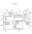
- Fig. 6 is a schematic side view of an automatic film development processor machine 1 which comprises a development unit 10 including a developer tank, a film leader feeder unit 9A for feeding the film leaders 9, a separator unit 11 for separating the film leaders 9 from the sheets of developed film, a film leader stocker unit 14 for receiving and storing the film leaders 9, a cartridge feeder unit 1A for feeding one by one the film cartridge cases 2 filled with the film cartridges 3, a cartridge stocker unit 1B for receiving and storing the cartridge cases 2, a conveyor belt 12 for conveying the film unloaded cartridges 3 from the cartridge feeder unit 1A to the cartridge stocker unit 1B, and a film rewinding station 7.
- a development unit 10 including a developer tank
- a film leader feeder unit 9A for feeding the film leaders 9
- a separator unit 11 for separating the film leaders 9 from the sheets of developed film
- a film leader stocker unit 14 for receiving and storing the film leaders 9
- a cartridge feeder unit 1A for feeding one by one the film cartridge cases 2 filled with the
- the film rewinding station 7 is arranged in which, as shown in Fig. 7, the film cartridge case 2 is placed on a pair of left and right rails 1C and advanced in a direction denoted by the arrow with its rack 27 engaged and driven by a drive gear 1D, and upon each of the sensor slits 31 of the film cartridge case 2 being detected by a sensor S, its corresponding cartridge pocket 25 stops just above a film takeup means 7A of the rewinding station 7. This is followed by unloading the sheet of undeveloped film 5 from its cartridge 3 with a film unloading means and rewinding it in the takeup means 7A.
- the film unloading means is designed for inserting its spool actuator shaft (not shown) through the spool actuator hole 37 of the cartridge pocket 25 to engage with and rotate the end of the spool 16 of the film cartridge 3 for unloading the undeveloped film sheet 5.
- Figs. 9 to 14 show a second embodiment not part of the present invention.
- Fig. 9 is a schematic view of a film development processor apparatus in which its entire arrangement is denoted by the numeral 1.
- a film cartridge case 2 for carrying therein a group of film cartridges 3 loaded with undeveloped films
- an unloading station 4 where a sheet of undeveloped film 5 is unloaded from its film cartridge 3 installed in the film cartridge case 2
- a rewinding unit 6 for rewinding the undeveloped film sheet 5 into a takeup cartridge 7.
- a splicer unit 8 for joining the exposed end of the undeveloped film sheet 5 from the takeup cartridge 7 with a film leader 9 for further transferring, a developer unit 10 for developing the undeveloped film sheet 5 headed with the film leader 9, a separator unit 11 for separating the developed film sheet 5 from the film leader 9, a film unloaded cartridge conveyor unit 12 for conveying the film unloaded cartridge 3 from which the undeveloped film sheet 5 has been unloaded at the unloading station 4, a loading station 13 where a developed film sheet 5 is loaded into the film unloaded cartridge 3, and a leader receiver unit 14 for receiving and storing a group of the film leaders 9 separated from their respective developed film sheets 5 at the separator unit 11.
- the film cartridge 3 to be held in the cartridge case 2 includes, as shown in Fig. 10, a casing 15 consisting of two separated synthetic resin members, a spool 16 rotatably mounted in the casing 15, and a cover 18 for closing a film outlet 17 to shield from external light.
- the cover 18 is actuated for opening and closing actions by a pivotal (operating) shaft 19 which is mounted through a side wall of the casing 15 to be driven with an opening and closing mechanism (not shown).
- a pivotal (operating) shaft 19 which is mounted through a side wall of the casing 15 to be driven with an opening and closing mechanism (not shown).
- the spool 16 is rotated with one (operating) end 20 engaged across the side wall of the casing 15 and driven by a rotating mechanism (not shown) for loading and unloading the film 5.
- the casing 15 of the cartridge 3 has an 1D bearing region 23 on the outer surface thereof for indicating an identification number of the cartridge 3. Also, a display window 22 is provided in the side wall of the casing 15 where the operating end 20 of the spool 15 is exposed and for displaying either unused or used condition of the cartridge 3, state of the development, presence or absence of the available frames, etc.
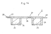
- the cartridge case 2 for holding a group of the film cartridges 3 is illustrated in more details in Figs. 11 to 14.
- the cartridge case 2 holds and carries the film cartridges 3 from the unloading station 4 to the loading station 13 and comprises two, left and right, rows of cartridge pockets 25, five pockets in each row, extending along both sides of a link plate 26 and in the moving direction W.
- the cartridge pocket 25 has a bottom 24 thereof tailored to match the shape of the film cartridge 3 shown in Fig. 10.
- a rack or conveyor element 27 for engagement with a cartridge conveying means described later (not shown in Figs. 11 to 14) is provided on one side of each row of the cartridge pockets 25.
- two flanges 28 are provided on both outer sides of the rows of the cartridge pockets 25, extending in the moving direction W of the cartridge case 2.
- one of the two flanges 28 on the left of the moving direction W of the cartridge case 2 has a plurality of V-shaped (positioning) notches 30 provided in an outer edge thereof for positioning the cartridge case 2 in relation to each cartridge pocket 25.
- the other flange 28 has a plurality of slit detection elements 31 provided in an outer edge thereof for use to indicate the cartridge case 2 being positioned in relation to the target cartridge pocket 25.
- Each of the bottoms 24 of the cartridge pockets 25 which are aligned in two rows between the flanges 28 and leveled lower than the transfer elements 27 has a readout window 33 for viewing the 1D bearing region 23 of the film cartridge 3 held in the pocket 25 and a through aperture 34 for passing the film sheet 5 unloaded from or loaded into its cartridge 3 through the film outlet 17.
- the bottom 24 of the cartridge pocket 25 is provided at one side with a vertically extending holddown means 36 for pressing down with its lower semicircular projecting portion 35 the casing 15 of the film cartridge 3 thus to hold the cartridge 3 in a correct orientation, and at the other side with a spool actuating hole 37 through which the operating end 20 of the spool 16 in the cartridge 3 is engaged with and actuated by the rotating mechanism for loading and unloading the film 5 and a cover actuating hole 38 through which the pivotal shaft 19 of the cover 18 is actuated by the unshown mechanism for opening and closing the film outlet 17 of the cartridge 3.
- a desired number of the film cartridges 3 loaded with undeveloped films 5 are installed by an operator in the cartridge pockets 25 of each cartridge case 2.
- each spool 16 When two rows of the film cartridges 3 are correctly placed in the cartridge pockets 25 of the cartridge case 2 and secured with the holddown portions 35 of the same respectively, the operating end 20 of each spool 16 is aligned with the spool actuating hole 37 of the cartridge pocket 25, the film outlet 17 with the through aperture 34, and the pivotal shaft 19 of each cover 18 with the cover actuating hole 38. Simultaneously, the 1D bearing region 23 of each cartridge 3 is located and viewed through the readout window 33.
- the film cartridges 3 in the cartridge case 2 are delivered in a succession by an unshown transfer mechanism to the rewinding station 6 where the undeveloped film sheet 5 is transferred from its film cartridge 3 to the takeup cartridge 7.
- the V-shaped notches 30 of its flange 28 come in engagement with correspondingly shaped projections provided on the rewinding station 6 (not shown) and the slit detection elements 31 of its other flange 28 are detected.
- the cover 18 of the film outlet 17 of the cartridge 3 is opened by the cover actuating mechanism coupling across the through hole 38 and turning the pivotal shaft 19.
- the spool 16 is rotated as its operating end 20 engaged through the spool actuating hole 37 with the spool actuating mechanism so that the undeveloped film sheet 5 is unloaded from its cartridge 3.
- the undeveloped film sheet 5 is then rewound into the takeup cartridge 7 when its trailing end has been detached from the spool 16 of the cartridge 3 by an automatic detaching device not shown.
- the 1D bearing region 23 of the cartridge 3 is read out and recorded on a controller (not shown) and the trailing end of the undeveloped film sheet 5 by a recording means such as a magnetic head.
- the V-shaped notches 30 of the cartridge case 2 are disengaged from the corresponding projections. This is followed by advancing the cartridge case 2 one step so that the succeeding film cartridge 3 comes to the unloading station 4.
- the undeveloped film sheets 5 of all the film cartridges 3 in the cartridge case 2 are unloaded and rewound in a succession by repeating the above procedure.
- the trailing end of the undeveloped film sheet 5 rewound in the takeup cartridge 7 is joined to the film leader 9 by the splicer unit 8 and then drawn out from the takeup cartridge 7 as guided by the film leader 9.
- the undeveloped film sheet 5 is then subjected to the development, bleaching, fixing, drying, and other known processes, and separated from its film leader 9 by the separator unit 11.
- the succeeding undeveloped film sheets 5 are unloaded from the remaining film cartridges 3 and rewound in a succession into the takeup cartridges 7.
- the film unloaded cartridges 3 in the film cartridge case 2 are then conveyed by the unloaded cartridge conveyor unit 12 to the loading station 13.
- the film cartridge case 2 is positioned with the V-shaped notches 30 of its flange 28 engaged with corresponding projections of the loading station 13.
- the positioning of the cartridge case 2 is detected as the slit detection elements 31 of its other flange 28 are read.
- This is followed by actuating the pivotal shaft 19 for turning the cover 18 to open the film outlet 17 of the film cartridge 3 with the cover actuator inserted through the through aperture 38.
- the developed film sheet 5 is then identified by comparing its 1D record with the 1D data of the 1D bearing region 23 on the film cartridge 3, and loaded back with its end (i.e. the trailing end of the undeveloped film form) through the film outlet 17 onto the spool 16 of the film cartridge 3.
- the operating end 20 of the spool 16 is then linked across the spool actuating hole 37 and rotated by the spool actuating mechanism for taking up the developed film sheet 5 in its cartridge 3.
- the film cartridges 3 loaded with their respective developed film sheets 5 are then picked out from the film cartridge case 2 as their casings 15 have easily been detached from the corresponding holding projections 35 of the cartridge pockets 25.
- the film cartridge case of the present invention is not limited to the use with a film development processor machine but may also be applicable to a photographic printing apparatus or a cartridge stocker apparatus.
Landscapes
- Physics & Mathematics (AREA)
- General Physics & Mathematics (AREA)
- Photographic Developing Apparatuses (AREA)
- Photographic Processing Devices Using Wet Methods (AREA)
Claims (7)
- Réceptacle de cassettes de film (2) comprenant plusieurs poches de cassette (25), retenant et supportant un groupe de cassettes de film (3), en vue du transfert de pellicules de film non développées chargées dans les cassettes de film respectives (3) vers une unité de développement d'un dispositif de développement automatique de films photographiques,
caractérisé en ce que chaque poche de cassette comporte une saillie de prévention d'un mauvais positionnement de la cassette (2B), agencée à l'intérieur de la poche au niveau d'une région proche de la base de la poche d'une paroi interne de celle-ci, formée de sorte à s'engager dans un gradin (3D) entourant une fenêtre de lecture d'un code à barres (3C) dans la cassette de film (3) lors du positionnement de la cassette de film (3) dans une orientation correcte dans la poche de cassette (25). - Réceptacle de cassettes de film selon la revendication 1, dans lequel la poche de cassette (25) comporte une saillie de retenue élastique (36) agencée sur l'autre coté de la paroi interne, en vue de l'ajustement dans le trou central (20) de la bobine de la cassette du film (3) par suite de l'élasticité de la cassette de film, pour retenir ainsi la cassette de film (3) à l'intérieur de la poche de cassette.
- Réceptacle de cassettes de film selon la revendication 1, comprenant:un moyen de retenue (36) destiné à retenir de façon amovible les cassettes de film (3) dans leurs poches de cassette respectives;un dispositif de transport (27), agencé de sorte à s'engager dans un moyen de transport des cassettes du dispositif de développement automatique de films.
- Réceptacle de cassettes de film selon la revendication 3, dans lequel le moyen de retenue (36) comprend une saillie de retenue (36) agencée sur un côté de la paroi interne de la poche de cassette (25), faisant face à la paroi interne comportant ladite saillie de prévention d'un mauvais positionnement de la cassette, pour presser la cassette de film (3) vers l'intérieur de la poche par suite de son élasticité, pour retenir de façon amovible et positionner la cassette dans la poche de cassette (25).
- Réceptacle de cassettes de film selon les revendications 3 ou 4, dans lequel la cassette de film (3) devant être agencée dans une poche de cassette du réceptacle de cassettes de film englobe un couvercle destiné à ouvrir et à fermer un orifice de sortie du film et à assurer une protection contre la lumière.
- Réceptacle de cassettes de film selon l'une quelconque des revendications 3 à 5, dans lequel le dispositif de transport (27) comprend un élément d'engagement destiné à s'engager dans le moyen de transport de la cassette du dispositif de développement automatique de films, et des éléments de positionnement destinés à positionner les poches de cassette du réceptacle de cassettes dans le dispositif de développement automatique de films, le positionnement des poches de cassette étant détecté dans le dispositif de développement automatique de films par des éléments de détection (31) agencés dans le réceptacle de cassettes de film.
- Réceptacle de cassettes de film selon l'une quelconque des revendications 3 à 6, comprenant en outre des brides de support agencées sur les deux bords latéraux correspondants.
Applications Claiming Priority (6)
| Application Number | Priority Date | Filing Date | Title |
|---|---|---|---|
| JP24012395 | 1995-09-19 | ||
| JP240123/95 | 1995-09-19 | ||
| JP24012395A JP3282462B2 (ja) | 1995-09-19 | 1995-09-19 | フィルムカートリッジケース |
| JP265711/95 | 1995-10-13 | ||
| JP26571195 | 1995-10-13 | ||
| JP26571195A JP3292001B2 (ja) | 1995-10-13 | 1995-10-13 | カートリッジの収納ケース |
Publications (2)
| Publication Number | Publication Date |
|---|---|
| EP0764882A1 EP0764882A1 (fr) | 1997-03-26 |
| EP0764882B1 true EP0764882B1 (fr) | 2001-11-21 |
Family
ID=26534587
Family Applications (1)
| Application Number | Title | Priority Date | Filing Date |
|---|---|---|---|
| EP96306512A Expired - Lifetime EP0764882B1 (fr) | 1995-09-19 | 1996-09-09 | Réceptacle pour cassette de film |
Country Status (6)
| Country | Link |
|---|---|
| US (1) | US5803386A (fr) |
| EP (1) | EP0764882B1 (fr) |
| KR (1) | KR100200402B1 (fr) |
| CN (2) | CN1077697C (fr) |
| CA (1) | CA2185281C (fr) |
| DE (1) | DE69617151T2 (fr) |
Citations (1)
| Publication number | Priority date | Publication date | Assignee | Title |
|---|---|---|---|---|
| EP0764833A1 (fr) * | 1995-09-23 | 1997-03-26 | Bayerische Motoren Werke Aktiengesellschaft, Patentabteilung AJ-3 | Mesure du tourbillonnement d'écoulements dans des conduits, en particulier pour une chambre de combustion simulée d'un moteur à piston |
Family Cites Families (21)
| Publication number | Priority date | Publication date | Assignee | Title |
|---|---|---|---|---|
| US3517896A (en) * | 1967-04-24 | 1970-06-30 | Bell & Howell Co | Magazine with readily removable cartridges |
| US3526406A (en) * | 1967-11-03 | 1970-09-01 | Newell Ind | Tape roll handling apparatus and roll therefor |
| DE1964727B2 (de) * | 1969-12-23 | 1972-02-24 | Agfa Gevaert AG, 5090 Leverkusen | Laufbildprojektor |
| US3667835A (en) * | 1970-04-15 | 1972-06-06 | Bell & Howell Co | Film cartridge attaching apparatus |
| US3674347A (en) * | 1970-06-25 | 1972-07-04 | Bell & Howell Co | Film cartridge support assembly for projectors |
| CH530034A (de) * | 1970-10-02 | 1972-10-31 | Gretag Ag | Vorrichtung zur Beschickung von automatischen Filmverarbeitungsmaschinen |
| US4221479A (en) * | 1979-02-23 | 1980-09-09 | Eastman Kodak Company | Camera film magazine |
| DE242817T1 (de) * | 1986-04-18 | 1988-03-17 | Filmzufuehrvorrichtung. | |
| US4910546A (en) * | 1988-04-27 | 1990-03-20 | Fuji Photo Film Co., Ltd. | Film processing device |
| US5210561A (en) * | 1990-06-18 | 1993-05-11 | Fuji Photo Film Co., Ltd. | Lens-fitted photographic film package and film feeder and package holder for film processor |
| US5032854A (en) * | 1990-07-31 | 1991-07-16 | Eastman Kodak Company | Photographic film cassette and camera apparatus and method |
| KR100190950B1 (ko) * | 1993-03-31 | 1999-06-15 | 니시모토 칸이치 | 필름을 리더에 연결하기 위한 장치 |
| JP2830968B2 (ja) * | 1993-04-15 | 1998-12-02 | ノーリツ鋼機株式会社 | リーダ、該リーダとフィルムの接続および分離方法、ならびに自動リーダ着脱式現像装置 |
| US5361113A (en) * | 1993-05-05 | 1994-11-01 | Eastman Kodak Company | Photographic film processing assembly |
| IT1265563B1 (it) * | 1993-06-16 | 1996-11-22 | San Marco Imaging Srl | Dispositivo di caricamento automatico di pellicole fotografiche per macchine sviluppatrici |
| US5296887A (en) * | 1993-06-23 | 1994-03-22 | Eastman Kodak Company | Bar-coded film spool |
| JP2943602B2 (ja) * | 1993-09-24 | 1999-08-30 | ノーリツ鋼機株式会社 | 写真処理装置 |
| EP0675408B1 (fr) * | 1994-03-28 | 2001-01-17 | Noritsu Koki Co., Ltd. | Dispositif pour le développement d'un film photographique |
| EP1126318B1 (fr) * | 1994-04-13 | 2005-01-19 | Noritsu Koki Co., Ltd. | Mécanisme d'enroulement de film pour un appareil de développement de film photographique |
| JP2914169B2 (ja) * | 1994-04-14 | 1999-06-28 | ノーリツ鋼機株式会社 | フィルム自動現像装置 |
| US5576794A (en) * | 1994-05-12 | 1996-11-19 | Eastman Kodak Company | Random batch photofinishing |
-
1996
- 1996-09-02 KR KR1019960037800A patent/KR100200402B1/ko not_active Expired - Fee Related
- 1996-09-09 DE DE69617151T patent/DE69617151T2/de not_active Expired - Fee Related
- 1996-09-09 EP EP96306512A patent/EP0764882B1/fr not_active Expired - Lifetime
- 1996-09-11 CA CA002185281A patent/CA2185281C/fr not_active Expired - Fee Related
- 1996-09-12 US US08/711,881 patent/US5803386A/en not_active Expired - Fee Related
- 1996-09-18 CN CN96112563A patent/CN1077697C/zh not_active Expired - Fee Related
-
2001
- 2001-04-26 CN CNB01117112XA patent/CN1201202C/zh not_active Expired - Fee Related
Patent Citations (1)
| Publication number | Priority date | Publication date | Assignee | Title |
|---|---|---|---|---|
| EP0764833A1 (fr) * | 1995-09-23 | 1997-03-26 | Bayerische Motoren Werke Aktiengesellschaft, Patentabteilung AJ-3 | Mesure du tourbillonnement d'écoulements dans des conduits, en particulier pour une chambre de combustion simulée d'un moteur à piston |
Also Published As
| Publication number | Publication date |
|---|---|
| KR970016746A (ko) | 1997-04-28 |
| US5803386A (en) | 1998-09-08 |
| DE69617151T2 (de) | 2002-06-06 |
| CN1317723A (zh) | 2001-10-17 |
| CA2185281C (fr) | 2000-10-17 |
| KR100200402B1 (ko) | 1999-06-15 |
| CN1201202C (zh) | 2005-05-11 |
| CA2185281A1 (fr) | 1997-03-20 |
| CN1166621A (zh) | 1997-12-03 |
| DE69617151D1 (de) | 2002-01-03 |
| CN1077697C (zh) | 2002-01-09 |
| EP0764882A1 (fr) | 1997-03-26 |
Similar Documents
| Publication | Publication Date | Title |
|---|---|---|
| US4153361A (en) | Web cassette with cartridge load | |
| EP0793142B1 (fr) | Système de traitement photographique comprenant un dispositif pour grouper les films selon des critères lus à partir des films eux-mêmes | |
| EP0685758A1 (fr) | Méthode et dispositif d'assemblage de cassettes de film photographique | |
| EP0764882B1 (fr) | Réceptacle pour cassette de film | |
| EP0676664B1 (fr) | Support de cartouche de film | |
| US4843412A (en) | Film supplying apparatus | |
| CA2185968C (fr) | Machine de developpement automatique de films | |
| EP0764883B1 (fr) | Appareil pour empiler des réceptacles de cassettes dans une machine automatique de développement de film | |
| US3766525A (en) | Apparatus for manipulating receptacles of exposed customer films | |
| US5450153A (en) | Photosensitive material handling apparatus | |
| US5910835A (en) | Photographic processing apparatus | |
| US5953806A (en) | Apparatus and method of loading lens-fitted photo film unit with photo film | |
| US3901435A (en) | Information carrier for use on exposed films and film-containing receptacles | |
| US5555067A (en) | Photographic film separating device and separation method | |
| JP3583211B2 (ja) | フィルム接合装置 | |
| EP0770921B1 (fr) | Appareil automatique de traitement de film | |
| JP3583210B2 (ja) | カートリッジの処理方法 | |
| EP0828192B1 (fr) | Appareil de traitement photographique | |
| JP3166479B2 (ja) | 自動スプライサー | |
| JP3545519B2 (ja) | フィルムキャリア | |
| JPH10186619A (ja) | カートリッジ入りフィルム搬送供給方法及び装置 | |
| JPH0980727A (ja) | フィルムカートリッジケース | |
| JPH03267939A (ja) | 現像装置用フイルム案内装置 | |
| JPH09120149A (ja) | カートリッジ識別位置決め装置 | |
| JPH09146252A (ja) | フィルム収納体ハンドリング装置 |
Legal Events
| Date | Code | Title | Description |
|---|---|---|---|
| PUAI | Public reference made under article 153(3) epc to a published international application that has entered the european phase |
Free format text: ORIGINAL CODE: 0009012 |
|
| 17P | Request for examination filed |
Effective date: 19961016 |
|
| AK | Designated contracting states |
Kind code of ref document: A1 Designated state(s): CH DE FR GB IT LI |
|
| 17Q | First examination report despatched |
Effective date: 19990916 |
|
| GRAG | Despatch of communication of intention to grant |
Free format text: ORIGINAL CODE: EPIDOS AGRA |
|
| GRAG | Despatch of communication of intention to grant |
Free format text: ORIGINAL CODE: EPIDOS AGRA |
|
| GRAG | Despatch of communication of intention to grant |
Free format text: ORIGINAL CODE: EPIDOS AGRA |
|
| GRAH | Despatch of communication of intention to grant a patent |
Free format text: ORIGINAL CODE: EPIDOS IGRA |
|
| GRAH | Despatch of communication of intention to grant a patent |
Free format text: ORIGINAL CODE: EPIDOS IGRA |
|
| GRAA | (expected) grant |
Free format text: ORIGINAL CODE: 0009210 |
|
| AK | Designated contracting states |
Kind code of ref document: B1 Designated state(s): CH DE FR GB IT LI |
|
| PG25 | Lapsed in a contracting state [announced via postgrant information from national office to epo] |
Ref country code: LI Free format text: LAPSE BECAUSE OF FAILURE TO SUBMIT A TRANSLATION OF THE DESCRIPTION OR TO PAY THE FEE WITHIN THE PRESCRIBED TIME-LIMIT Effective date: 20011121 Ref country code: IT Free format text: LAPSE BECAUSE OF FAILURE TO SUBMIT A TRANSLATION OF THE DESCRIPTION OR TO PAY THE FEE WITHIN THE PRESCRIBED TIME-LIMIT;WARNING: LAPSES OF ITALIAN PATENTS WITH EFFECTIVE DATE BEFORE 2007 MAY HAVE OCCURRED AT ANY TIME BEFORE 2007. THE CORRECT EFFECTIVE DATE MAY BE DIFFERENT FROM THE ONE RECORDED. Effective date: 20011121 Ref country code: CH Free format text: LAPSE BECAUSE OF FAILURE TO SUBMIT A TRANSLATION OF THE DESCRIPTION OR TO PAY THE FEE WITHIN THE PRESCRIBED TIME-LIMIT Effective date: 20011121 |
|
| REG | Reference to a national code |
Ref country code: CH Ref legal event code: EP |
|
| REG | Reference to a national code |
Ref country code: GB Ref legal event code: IF02 |
|
| REF | Corresponds to: |
Ref document number: 69617151 Country of ref document: DE Date of ref document: 20020103 |
|
| ET | Fr: translation filed | ||
| REG | Reference to a national code |
Ref country code: CH Ref legal event code: PL |
|
| PLBE | No opposition filed within time limit |
Free format text: ORIGINAL CODE: 0009261 |
|
| STAA | Information on the status of an ep patent application or granted ep patent |
Free format text: STATUS: NO OPPOSITION FILED WITHIN TIME LIMIT |
|
| 26N | No opposition filed | ||
| PGFP | Annual fee paid to national office [announced via postgrant information from national office to epo] |
Ref country code: GB Payment date: 20040908 Year of fee payment: 9 Ref country code: FR Payment date: 20040908 Year of fee payment: 9 |
|
| PGFP | Annual fee paid to national office [announced via postgrant information from national office to epo] |
Ref country code: DE Payment date: 20050902 Year of fee payment: 10 |
|
| PG25 | Lapsed in a contracting state [announced via postgrant information from national office to epo] |
Ref country code: GB Free format text: LAPSE BECAUSE OF NON-PAYMENT OF DUE FEES Effective date: 20050909 |
|
| GBPC | Gb: european patent ceased through non-payment of renewal fee |
Effective date: 20050909 |
|
| PG25 | Lapsed in a contracting state [announced via postgrant information from national office to epo] |
Ref country code: FR Free format text: LAPSE BECAUSE OF NON-PAYMENT OF DUE FEES Effective date: 20060531 |
|
| REG | Reference to a national code |
Ref country code: FR Ref legal event code: ST Effective date: 20060531 |
|
| PG25 | Lapsed in a contracting state [announced via postgrant information from national office to epo] |
Ref country code: DE Free format text: LAPSE BECAUSE OF NON-PAYMENT OF DUE FEES Effective date: 20070403 |