EP0764885B1 - Procédé de positionnement d'un masque par rapport à une pièce à traiter et appareil d' exposition par projection de mise en oeuvre de ce procédé - Google Patents
Procédé de positionnement d'un masque par rapport à une pièce à traiter et appareil d' exposition par projection de mise en oeuvre de ce procédé Download PDFInfo
- Publication number
- EP0764885B1 EP0764885B1 EP96115086A EP96115086A EP0764885B1 EP 0764885 B1 EP0764885 B1 EP 0764885B1 EP 96115086 A EP96115086 A EP 96115086A EP 96115086 A EP96115086 A EP 96115086A EP 0764885 B1 EP0764885 B1 EP 0764885B1
- Authority
- EP
- European Patent Office
- Prior art keywords
- workpiece
- mask
- exposure
- mam
- alignment marks
- Prior art date
- Legal status (The legal status is an assumption and is not a legal conclusion. Google has not performed a legal analysis and makes no representation as to the accuracy of the status listed.)
- Expired - Lifetime
Links
- 238000000034 method Methods 0.000 title claims description 46
- 230000008569 process Effects 0.000 title claims description 39
- 238000001514 detection method Methods 0.000 claims description 50
- 230000001678 irradiating effect Effects 0.000 claims description 2
- 238000005286 illumination Methods 0.000 description 31
- 230000003287 optical effect Effects 0.000 description 22
- 230000008901 benefit Effects 0.000 description 5
- 238000003780 insertion Methods 0.000 description 5
- 230000037431 insertion Effects 0.000 description 5
- 239000013307 optical fiber Substances 0.000 description 5
- 230000009471 action Effects 0.000 description 4
- 230000000694 effects Effects 0.000 description 3
- 238000003384 imaging method Methods 0.000 description 3
- 239000004065 semiconductor Substances 0.000 description 3
- 230000004075 alteration Effects 0.000 description 2
- 239000004973 liquid crystal related substance Substances 0.000 description 2
- 229920002120 photoresistant polymer Polymers 0.000 description 2
- 239000000758 substrate Substances 0.000 description 2
- 102100027237 MAM domain-containing protein 2 Human genes 0.000 description 1
- 101710116166 MAM domain-containing protein 2 Proteins 0.000 description 1
- 230000005540 biological transmission Effects 0.000 description 1
- 239000000969 carrier Substances 0.000 description 1
- 230000008859 change Effects 0.000 description 1
- 230000007423 decrease Effects 0.000 description 1
- 239000000428 dust Substances 0.000 description 1
- 230000001771 impaired effect Effects 0.000 description 1
- 230000009467 reduction Effects 0.000 description 1
- 230000000007 visual effect Effects 0.000 description 1
Images




Classifications
-
- G—PHYSICS
- G03—PHOTOGRAPHY; CINEMATOGRAPHY; ANALOGOUS TECHNIQUES USING WAVES OTHER THAN OPTICAL WAVES; ELECTROGRAPHY; HOLOGRAPHY
- G03F—PHOTOMECHANICAL PRODUCTION OF TEXTURED OR PATTERNED SURFACES, e.g. FOR PRINTING, FOR PROCESSING OF SEMICONDUCTOR DEVICES; MATERIALS THEREFOR; ORIGINALS THEREFOR; APPARATUS SPECIALLY ADAPTED THEREFOR
- G03F9/00—Registration or positioning of originals, masks, frames, photographic sheets or textured or patterned surfaces, e.g. automatically
-
- G—PHYSICS
- G03—PHOTOGRAPHY; CINEMATOGRAPHY; ANALOGOUS TECHNIQUES USING WAVES OTHER THAN OPTICAL WAVES; ELECTROGRAPHY; HOLOGRAPHY
- G03F—PHOTOMECHANICAL PRODUCTION OF TEXTURED OR PATTERNED SURFACES, e.g. FOR PRINTING, FOR PROCESSING OF SEMICONDUCTOR DEVICES; MATERIALS THEREFOR; ORIGINALS THEREFOR; APPARATUS SPECIALLY ADAPTED THEREFOR
- G03F9/00—Registration or positioning of originals, masks, frames, photographic sheets or textured or patterned surfaces, e.g. automatically
- G03F9/70—Registration or positioning of originals, masks, frames, photographic sheets or textured or patterned surfaces, e.g. automatically for microlithography
Definitions
- the invention relates to a process for positioning a mask relative to a workpiece and a device for executing the process in an exposure device which is used for production of a semiconductor device, a printed board, an LCD (liquid crystal display) and for similar purposes.
- Production of electrical and electronic components and parts of various types in which processing of structures in the micron range is necessary includes an exposure process.
- These electronic parts are semiconductor components, liquid crystal displays, printer heads of the inkjet type, and multichip modules in which a host of different electronic components are produced on a substrate and thus a module is formed, and the like.
- the above described positioning is conventionally done such that the alignment marks of the mask and the workpiece come to lie on top of one another.
- exposure devices of the projection type are known wherein positioning is done using exposure light, for example of an i-line, an h-line or a g-line (i-line: 365 nm wavelength, h-line: 405 nm wavelength, g-line: 436 nm wavelength), or wherein positioning is done using nonexposure light, as, for example, an e-line, a d-line or a c-line (e-line: 546 nm wavelength, d-line: 588 nm wavelength, c-line: 656 nm wavelength).
- the region of the circuit patterns is not limited by the positioning region, since the photoresist is not exposed to the action of exposure light during positioning.
- Figure 11 shows, schematically, an arrangement of the conventional exposure device in which positioning is done using the above described e-line.
- reference number 1 indicates an exposure light irradiation device or a nonexposure light irradiation device
- reference number 1a a lamp
- reference number 1b a focussing mirror
- reference number 1c a shutter
- reference number 1d an optical filter
- reference number 1e a condenser lens
- reference number 2 indicates a mask carrier on which mask M is attached by means of a vacuum chuck or the like and which is driven by means of a drive device not shown in the drawing in the X-Y-Z- ⁇ directions (X axis and Y axis being orthogonal axes on the plane parallel to one mask surface; Z axis being the axis in the vertical direction in Figure 11; ⁇ axis being the axis of rotation around the Z-axis).
- mask M On mask M, a mask pattern and mask alignment marks MAM, hereinafter referenced to as mask marks, are recorded for purposes of positioning.
- Reference number 3 indicates a projection lens and reference letter W indicates a workpiece.
- Workpiece alignment marks WAM hereinafter referenced to as workpiece marks, are recorded on workpiece W for purposes of positioning.
- Reference number 5 indicates an alignment mark detection unit which consists of lens 5a, objective lens 5b, half mirror 5c and image converter 5d which has a CCD camera.
- Workpiece mark WAM and mask mark MAM which is projected onto the workpiece W, are detected via half mirror 5c, objective lens 5b and lens 5a by means of image converter 5d, and thus the positions of the two marks are observed.
- alignment mark detection unit 5 is shown only once. However, there are several alignment units 5 (at least at two locations) since there are several mask marks MAM and several workpiece marks WAM (each at least at two locations) each on mask M and workpiece W, and because alignment unit 5 is assigned according to the respective alignment mark.
- alignment mark detection units 5 are ordinarily formed such that they can be removed in the direction of the arrow according to Figure 11. During exposure, alignment mark detection units 5 are removed when they extend within the exposure area.
- Alignment mark detection units 5 can be located in area B as shown. Moreover, they can also be located in additionally shown area A or area C.
- the e-line as nonexposure light, is emitted first from exposure light (or nonexposure light) irradiation device 1 via optical filter 1d and, by means of alignment mark detection units 5, workpiece marks WAM and mask marks MAM, projected onto workpiece W, are detected.
- This method of determining mask marks MAM projected onto the workpiece by the projection lens is called TTL, i.e., the "through the lens", method.
- detected mask marks MAM and workpiece marks WAM are displayed on a monitor, which is not shown in the drawing, and by watching the monitor, an operator moves mask carrier 2 and/or a workpiece carrier 4 such that the two marks agree with one another.
- optical filter 1d is removed from the optical path, the i-line, as exposure light, is then emitted from exposure light (or nonexposure light) irradiation device 1, the mask pattern is projected onto workpiece W, and exposure is effected.
- the deviation of the projection surfaces is corrected by inserting a parallel flat plate in the optical path of the projection optics system and, according to the wavelengths of the nonexposure light, by changing the plate thickness or adjusting the plate tilt (JP patent HEI 5-43168).
- the deviation of the projection images by the exposure light and the nonexposure light is corrected by inserting the parallel flat plate between the projection lens and the workpiece.
- the property being that, by inserting the parallel flat plate in the optical path, the focal position deviates by ⁇ S, as is illustrated in Figure 13.
- positioning using the nonexposure light has the advantage that the pattern can be formed in the vicinity of the alignment marks. But then it is necessary to correct the length of the optical path using the parallel flat plate and the like. This results in various disadvantages.
- Reference number 1 indicates the exposure light (or nonexposure light) irradiation device
- reference number 2 indicates the mask carrier
- reference letter M indicates the mask on which a mask pattern and the mask alignment marks MAM are recorded for positioning
- Reference number 3 indicates the projection lens
- reference letter W indicates the workpiece on which workpiece marks WAM are recorded for purposes of positioning.
- reference number 4 indicates the workpiece carrier on which total reflection or half mirror 4a is installed and which is driven by means of a drive device which is not shown in the drawing in the X-Y-Z- ⁇ directions.
- Reference symbol WAI indicates an alignment mark partial illumination system.
- the nonexposure light which is emitted from a light source not shown in the drawing is incident via optical fibers 6a, lens 6b and mirror 6c on half mirror 5e of alignment unit 5 and irradiates workpiece mark WAM on workpiece W.
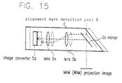
- Figure 15 schematically shows a case in which the stopping position of alignment mark detection unit 5 changes.
- the stopping position of alignment mark detection unit 5 is identical to the position in Figure 15 by the broken line, the imaging position of mask mark MAM (or of workpiece mark WAM) on image converter 5d, changes accordingly.
- step and repeat exposure only the positions of workpiece marks WAM are, however, detected and stored starting the second time. Therefore, in this case, it is possible that deviations occur from the position of mask mark MAM which was stored the first time.
- the alignment accuracy is usually roughly ⁇ 1 micron.
- a positioning accuracy of alignment mark detection unit 5 of roughly ⁇ 0.1 microns (roughly 1/10 of the accuracy of alignment of mask M to workpiece W) is necessary in order that the deviations of workpiece marks WAM from the stored position of mask mark MAM lie within this range. It is difficult to do this mechanically with each insertion and removal of alignment mark detection unit 5.
- a projection exposure apparatus comprises several detection optical systems in order to ensure proper alignment of the optical components. Also in US-A-4,962,318 an exposure apparatus is disclosed which is able to align a substrate to be exposed.
- the invention was made in order to eliminate the above described disadvantages of the prior art and, specifically, the above described disadvantage with respect to the reproducibility of the insertion position of the alignment units.
- the first object of the invention is to provide a process, and a device for executing the process, which positions a mask relative to a workpiece in which the positioning of the mask can be done without using a parallel flat plate, regardless of the characteristic of the projection lens, and with high precision. Also, the process can be advantageously used for step and repeat exposure.
- a second object of the invention is to devise a process, and a device for executing the process, which positions a mask relative to a workpiece in which, even in the case of difficult identification of workpiece marks, as in the case of overlapping of mask marks with the workpiece marks or the like, the relative positions of the mask marks and the workpiece marks can be easily and automatically determined and positioning can be done with high precision within a short time.
- positioning of the mask relative to the workpiece can be done without using a parallel flat plate and with high precision, regardless of the characteristic of the projection lens.
- the process by which the positions of the mask alignment marks and workpiece alignment marks are determined separately makes it possible to prevent the identification of the workpiece alignment marks from becoming difficult due to the influence of the mask alignment marks or the mask pattern and the like, and the relative positions of the two alignment marks can be easily determined. In this way, positioning can be done in a short time with high precision auto alignment.
- the same effect is obtained as in the above solutions.
- the projection images of the mask marks can be detected and the above described positions can be stored by the workpiece remaining attached to the workpiece carrier. Therefore alignment can be done with high accuracy without any effect being exerted by the accuracy of the insert positions of the alignment units.
- Figure 1 is a schematic of a first embodiment of the invention. This embodiment relates to the execution of the above described step and repeat exposure. In the embodiment described below, step and repeat exposure is explained. However, the invention can be used not only for step and repeat exposure, but also for the exposure described above using the conventional example.
- Reference number 1 indicates the exposure light (respectively non-exposure light) irradiation device; reference number 1a, the lamp; reference number 1b, the focussing mirror; reference number 1c, the shutter; reference number 1d, the optical filter; and reference number 1e, the condenser lens.
- Reference number 2 indicates the mask carrier which is driven by means of a drive device (not shown in the drawing) in the X-Y-Z- ⁇ directions.
- Reference letter M indicates the mask on which a mask pattern and mask alignment marks MAM are recorded for positioning purposes.
- Reference symbol MA1 labels a mask alignment mark partial illumination system for irradiating mask M with exposure light. Furthermore, reference number 7a indicates optical fibers for introducing the partial illumination light; reference number 7b, a lens; and reference number 7c, a mirror.
- Reference number 3 indicates the projection lens while reference letter W indicates the workpiece on which workpiece marks WAM are recorded for purposes of positioning.
- Reference number 4 furthermore indicates the workpiece carrier on which total reflection or half mirror 4a is installed.
- the workpiece carrier is driven by means of a drive device (not shown in the drawing) in the X-Y-Z- ⁇ directions. It is desirable that mirror 4a be a half mirror as is described below.
- Figure 2 (a) illustrates workpiece carrier 4 as viewed from overhead in Figure 1.
- the site shown by the broken line designates the workpiece W attachment site.
- On workpiece W are several exposure zones as is shown in the drawing.
- the height of mirror 4a be set to the normal height H of workpiece W as is shown in Figure 2 (b).
- workpiece carrier 4 can be moved in the Z-direction (vertically in Figure 1); the amount of movement in the Z-direction when the reflection surface of mirror 4a agrees with the mask pattern projection surface can be reduced; and the accuracy can be increased, as is described above.
- reference number WA1 indicates the alignment mark partial illumination system.
- the nonexposure light which is emitted from a light source (not shown in the drawing) is incident, via optical fibers 6a, lens 6b and mirror 6c, on half mirror 5e of alignment unit 5 and irradiates workpiece mark WAM on workpiece W. Furthermore, the nonexposure light can be emitted from exposure light (or nonexposure light) irradiation device 1 via optical filter Id onto workpiece W without placing alignment-mark partial illumination system WA 1, as is described below.
- Reference number 5 indicates the alignment mark detection unit which consists of lens 5a, objective lens 5b, half mirrors 5c and 5e and image converter 5d which includes the CCD camera.
- Mask mark MAM which is projected onto mirror 4a located on workpiece carrier 4, and workpiece mark WAM irradiated by the above described alignment mark partial illumination system WA1, are detected via half mirror 5c, objective lens 5b, half mirror 5e, and lens 5a by means of image converter 5d.
- alignment mark detection unit 5 and partial illumination system WA1 are assigned according to the number of mask marks and workpiece marks, i.e., each are located at least at two sites.
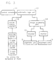
- FIG 3 is a schematic of the arrangement of a system for controlling the exposure device according to the invention.
- reference number 11 indicates a control console; reference number 12, an arithmetic-logic unit for control of the projection exposure device shown in Figure 1; and reference number 13, a carrier control element which adjusts mask carrier 2 and workpiece carrier 4, which are shown in Figure 1 in the X-Y-Z- ⁇ directions.
- Reference number 14 indicates an image processing part which recognizes mask mark MAM detected by means of image converter 5d of alignment mark detection unit 5, stores the position coordinates of the MAM, then recognizes workpiece mark WAM detected by means of image converter 5d of alignment mark detection unit 5 and determines the position coordinates of the WAM, as is described below. Furthermore, arithmetic-logic unit 12 determines the difference between the above described position coordinates of mask mark MAM and the above described position coordinates of workpiece mark WAM which have been determined in image processing part 14. Carrier control element 13 moves mask carrier 2 and/or workpiece carrier 4 such that the two agree with one another. Mask mark MAM and workpiece mark WAM, detected by alignment mark detection units 5, are displayed on monitor 15.
- workpiece mark WAM can be irradiated by nonexposure light and the position coordinates of workpiece mark WAM can be determined, and positioning of the mask to the workpiece can be done without using the parallel flat plate, regardless of the characteristic of the projection lens, and with high precision.
- mirror 4a is positioned on workpiece carrier 4, by which 1) workpiece carrier 4 is moved in the X-Y directions such that mirror 4a is positioned in the projection site of mask mark MAM; 2) the reflection surface of mirror 4a is brought into agreement with mask pattern projection surface Zo, by which, by emission of exposure light, mask mark MAM is projected onto mirror 4a and the position coordinates of mask mark MAM are stored; 3) then emission of the above described exposure light is stopped; 4) workpiece carrier 4 is moved such that the position of workpiece mark WAM in the exposure zone as the article to be exposed on workpiece W, is brought essentially into agreement with the projection site of mask mark MAM, and by which 5) the surface of workpiece W is brought into agreement with the mask pattern projection surface.
- the projection image of mask mark MAM can be detected and its position stored, while workpiece W remains attached on workpiece carrier 4. Therefore, in the above described position, the two alignment marks can be detected, even if the insertion position of alignment mark detection unit 5 differs upon each exposure. In this way, a reduction of alignment accuracy can be prevented.
- the process by which the positions of mask marks MAM and the positions of workpiece marks WAM are determined separately prevents the identification of the workpiece marks from becoming difficult due to the influence of mask marks MAM or the mask pattern or the like.
- the relative positions of the mask marks and the workpiece marks can be easily determined and therefore positioning can be done with high precision within a short time by auto alignment.
- Figure 6 is a schematic of a second embodiment of the invention.
- the same parts as in Figure 1 are provided with the same reference numbers as in Figure 1.
- aperture 8 instead of the arrangement of mask alignment partial illumination system MA1 in Figure 1, there is aperture 8 which is inserted and removed on mask M. When the mask is aligned, exposure light is emitted from openings of the aperture onto the mask.
- Other arrangements are identical to the embodiment in Figure 1.
- Figure 7 is a view in which above described aperture 8 is viewed from overhead in Figure 6. As is shown in Figure 7, in aperture 8, there are openings which correspond to the sites provided with mask marks MAM.
- the size of workpiece carrier 4 and its amount of movement in the X-Y directions is greater than in the first embodiment, and that the distance between the workpiece arrangement site and mirror 4a is greater than in the first embodiment. In this way, when the mask is aligned, it is possible to prevent workpiece W from being exposed by the exposure light which emerges from the openings of aperture 8.
- Figure 8 is a schematic of workpiece carrier 4 according to a third embodiment of the invention in which workpiece carrier 4 is viewed from overhead.
- mirror 4a is located in a position which is completely removed from the workpiece arrangement site on workpiece carrier 4, as is shown in the drawing. This prevents exposure light from being emitted onto workpiece W when exposure light is emitted onto mask M in mask alignment from exposure light (or nonexposure light) irradiation device 1.
- mask alignment partial illumination system MA1 is removed from the parts in Figure 1, or aperture 8 is removed from the parts in Figure 6. Furthermore, in this case, the size/arrangement of the mirror on workpiece carrier 4 is changed and the amount of movement of workpiece carrier 4 in the X-Y directions is increased, while other arrangements are identical to the arrangements in Figures 1 and 6.
- process steps (6) through (22) are repeated and the respective exposure zone of workpiece W is exposed.
- the exposure light can be emitted from exposure light (or nonexposure light) irradiation device 1, as was described above.
- the emission of nonexposure light in the respective embodiment can be done via optical filter 1d from exposure light (or nonexposure light) irradiation device 1, instead of using alignment mark partial illumination systems WA1.
- both the mask carrier and the workpiece carrier have certain inaccuracies in the amount of their movements. It is therefore necessary, after moving the carriers in the stipulated amount for purposes of positioning, to again confirm the position ratio between mask marks MAM and workpiece marks WAM and to repeat positioning if the amount of position deviation is not less than or equal to an allowable value.
- the exposure light is emitted onto mask marks MAM and that the positions of position coordinates (XM, YM) of its projection images are stored.
- the above described projection images must be projected onto the workpiece with the resist on the workpiece being exposed to the action of exposure light.
- the process of the present invention by which, on the workpiece carrier in one position, there is a reflection component which is removed from the workpiece attachment site; by which the mask alignment marks are projected onto the reflection component; by which their relative positions are determined/stored; by which then the workpiece carrier provided with the workpiece is moved into a position in which the alignment marks on the mask are projected onto the above described workpiece; by which the nonexposure light is emitted onto the alignment marks of the workpiece; by which the relative positions of the workpiece alignment marks are determined/stored; by which the data of the relative positions of the mask alignment marks and the workpiece alignment marks are computed; and by which the workpiece and/or the mask is/are moved such that the two alignment marks come to rest on top of one another.
Landscapes
- Physics & Mathematics (AREA)
- General Physics & Mathematics (AREA)
- Exposure And Positioning Against Photoresist Photosensitive Materials (AREA)
- Exposure Of Semiconductors, Excluding Electron Or Ion Beam Exposure (AREA)
Claims (4)
- Procédé de positionnement d'un masque (M) par rapport à une pièce à traiter dans un dispositif d'exposition par projection possédant une lentille de projection (3), comprenant les étapes de :positionnement d'unités (5) de détection de repères d'alignement entre ladite lentille de projection (3) et un porte-pièce (4) ;émission d'une lumière d'exposition à partir d'un premier dispositif (MA1, 1, 8) d'émission d'un rayonnement lumineux sur des repères d'alignement (MAM) du masque (M) ;utilisation de ladite lumière d'exposition et de ladite lentille de projection (3) pour former des images de projection desdits repères d'alignement (MAM) du masque (M) sur un élément de réflexion (4a) situé sur ledit porte-pièce, ledit élément de réflexion (4a) étant situé à distance d'un site de fixation de la pièce à traiter ;détection desdites images de projection avec lesdites unités (5) de détection des repères d'alignement et soumission desdites images de projection à un traitement d'images,calcul et stockage des positions desdites images de projection ;arrêt de l'émission de la lumière d'exposition venant du premier dispositif (MA1, 1, 8) d'émission d'un rayonnement lumineux dans un état dans lequel lesdites unités (5) de détection des repères d'alignement sont positionnées;déplacement du porte-pièce (4) sur lequel la pièce à traiter (W) est positionnée dans une position pour laquelle la surface de ladite pièce (W) correspond à la surface de projection du motif du masque ;émission d'une lumière de non-exposition à partir soit du premier dispositif (MA1, 1, 8) d'émission d'un rayonnement lumineux, soit d'un second dispositif (WA1) d'émission d'un rayonnement lumineux, ceci sur des repères d'alignement (WAM) de la pièce à traiter (W);détection des repères d'alignement (WAM) de la pièce à traiter (W) avec lesdites unités (5) de détection des repères d'alignement et soumission des repères d'alignement (WAM) de la pièce à traiter (W) à un traitement d'images ;calcul et stockage des positions des repères d'alignement (WAM) de la pièce à traiter (W) ;calcul informatisé des données des positions relatives des repères d'alignement (MAM, WAM) du masque (M) et de la pièce à traiter (W) ;déplacement d'au moins l'un d'entre la pièce à traiter (W) et le masque (M) de telle sorte que les repères d'alignement (MAM, WAM) du masque (M) et de la pièce à traiter (W) viennent reposer en correspondance les uns avec les autres ; etretrait desdites unités (5) de détection des repères d'alignement.
- Procédé de positionnement d'un masque (M) par rapport à une pièce à traiter (W) selon la Revendication 1, comprenant les étapes de :déplacement du porte-pièce (4) de telle façon que les zones d'exposition respectives de la pièce à traiter (W) soient successivement déplacées jusqu'à une position d'exposition ;émission d'une lumière d'exposition sur ledit masque (M), exposant ainsi les zones d'exposition respectives de la pièce à traiter (W) par étapes.
- Appareil d'exposition par projection pour mettre en oeuvre un procédé selon la Revendication 1, comprenant :caractérisé en ce queun masque (M) comportant des repères d'alignement (MAM) ;un porte-masque (2) destiné à recevoir le masque (M) ;une lentille de projection (3) ;un porte-pièce (4) destiné à recevoir une pièce à traiter (W) à un site de fixation de la pièce à traiter ;un premier moyen (MA1, 1, 8) d'émission d'un rayonnement lumineux, destiné à illuminer un des repères d'alignement (MAM) du masque et un motif de masque avec au moins une lumière de non-exposition et une lumière d'exposition, dans lequel des images de projection des repères d'alignement (MAM) du masque (M) sont projetées par la lumière d'exposition émise depuis le premier moyen (MA1, 1, 8) d'émission d'un rayonnement lumineux ;un élément de réflexion (4a) situé sur le porte-pièce (4) dans une position située à distance du site de fixation de la pièce à traiter, destiné à réfléchir lesdites images de projection ;un second moyen (WA1) d'émission d'un rayonnement lumineux, destiné à émettre de la lumière, dans lequel les repères d'alignement (WAM) de la pièce à traiter sont illuminés par une lumière de non exposition provenant de l'un d'entre ledit premier moyen (MA1, 1, 8) d'émission d'un rayonnement lumineux et ledit second moyen (WA1) d'émission d'un rayonnement lumineux ;des unités (5) de détection de repères d'alignement, destinées à détecter les images de projection des repères d'alignement (MAM) du masque et des repères d'alignement (WAM) de la pièce à traiter ;des moyens (14) pour soumettre les images de projection des repères d'alignement (MAM) du masque et des repères d'alignement (WAM) de la pièce à traiter à un traitement d'images ;des moyens pour calculer et stocker les positions des images de projection des repères d'alignement (MAM) du masque et des repères d'alignement (WAM) de la pièce à traiter ;des moyens (12) pour le calcul informatisé des données des positions relatives des repères d'alignement (MAM, WAM) du masque (M) et de la pièce à traiter (W) ;des moyens (2, 4) pour déplacer au moins l'un d'entre la pièce à traiter (W) et le masque (M) de telle sorte que les repères d'alignement (MAM, WAM) du masque (M) et de la pièce à traiter (W) viennent reposer en correspondance les uns avec les autres ; etdes moyens pour contrôler l'émission de la lumière d'exposition venant du premier moyen d'émission (MA1, 1, 8) d'un rayonnement lumineux,les unités (5) de détection des repères d'alignement destinés à détecter les repères d'alignement de la plaquette (WAM) sont les mêmes que les unités (5) de détection des repères d'alignement destinées à détecter les images de projection des repères d'alignement du masque (MAM) ; etlesdites unités (5) de détection des repères d'alignement sont mobiles entre une position située entre ladite lentille de projection (3) et ledit porte-pièce (4) et une position écartée.
- Appareil d'exposition par projection selon la Revendication 3, dans lequel :
ledit porte-pièce (4) est prévu pour porter une pièce à traiter (W) avec plusieurs zones d'exposition, les zones d'exposition respectives étant successivement mobiles jusqu'à une position d'exposition par déplacement du porte-pièce (4).
Applications Claiming Priority (3)
| Application Number | Priority Date | Filing Date | Title |
|---|---|---|---|
| JP23978395 | 1995-09-19 | ||
| JP7239783A JP2994991B2 (ja) | 1995-09-19 | 1995-09-19 | マスクとワークの位置合わせ方法および装置 |
| JP239783/95 | 1995-09-19 |
Publications (3)
| Publication Number | Publication Date |
|---|---|
| EP0764885A2 EP0764885A2 (fr) | 1997-03-26 |
| EP0764885A3 EP0764885A3 (fr) | 1997-10-22 |
| EP0764885B1 true EP0764885B1 (fr) | 1999-12-08 |
Family
ID=17049827
Family Applications (1)
| Application Number | Title | Priority Date | Filing Date |
|---|---|---|---|
| EP96115086A Expired - Lifetime EP0764885B1 (fr) | 1995-09-19 | 1996-09-19 | Procédé de positionnement d'un masque par rapport à une pièce à traiter et appareil d' exposition par projection de mise en oeuvre de ce procédé |
Country Status (6)
| Country | Link |
|---|---|
| US (1) | US5881165A (fr) |
| EP (1) | EP0764885B1 (fr) |
| JP (1) | JP2994991B2 (fr) |
| KR (1) | KR100422722B1 (fr) |
| DE (1) | DE69605512T2 (fr) |
| TW (1) | TW448345B (fr) |
Families Citing this family (25)
| Publication number | Priority date | Publication date | Assignee | Title |
|---|---|---|---|---|
| JP2856711B2 (ja) * | 1996-07-16 | 1999-02-10 | 山形日本電気株式会社 | 位置検出方法 |
| JP3445100B2 (ja) * | 1997-06-02 | 2003-09-08 | キヤノン株式会社 | 位置検出方法及び位置検出装置 |
| US6002426A (en) * | 1997-07-02 | 1999-12-14 | Cerprobe Corporation | Inverted alignment station and method for calibrating needles of probe card for probe testing of integrated circuits |
| EP1089327A4 (fr) * | 1998-03-06 | 2003-01-02 | Nikon Corp | Dispositif d'exposition et procede de fabrication de dispositif a semi-conducteurs |
| JPH11312635A (ja) * | 1998-04-28 | 1999-11-09 | Ushio Inc | コンタクト露光方法 |
| US8632590B2 (en) | 1999-10-20 | 2014-01-21 | Anulex Technologies, Inc. | Apparatus and methods for the treatment of the intervertebral disc |
| US7004970B2 (en) | 1999-10-20 | 2006-02-28 | Anulex Technologies, Inc. | Methods and devices for spinal disc annulus reconstruction and repair |
| US7615076B2 (en) | 1999-10-20 | 2009-11-10 | Anulex Technologies, Inc. | Method and apparatus for the treatment of the intervertebral disc annulus |
| JP2002131923A (ja) | 2000-10-25 | 2002-05-09 | Ushio Inc | 基板用逐次露光装置 |
| JP4740405B2 (ja) * | 2000-11-09 | 2011-08-03 | 東京エレクトロン株式会社 | 位置合わせ方法及びプログラム記録媒体 |
| TW200404485A (en) * | 2002-05-22 | 2004-03-16 | Assembleon Nv | Method of placing a component by means of a placement device at a desired position on a substrate holder, and device suitable for performing such a method |
| JP3643572B2 (ja) * | 2002-05-31 | 2005-04-27 | 株式会社アドテックエンジニアリング | 投影露光装置及び位置合わせ装置 |
| JP4158514B2 (ja) | 2002-12-24 | 2008-10-01 | ウシオ電機株式会社 | 両面投影露光装置 |
| DE102005021048A1 (de) * | 2005-05-06 | 2006-12-28 | Infineon Technologies Ag | Vorrichtung zum Stabilisieren eines Werkstücks bei einer Bearbeitung |
| JPWO2008139955A1 (ja) * | 2007-05-07 | 2010-08-05 | 株式会社目白プレシジョン | 投影露光方法、アライメント方法及び投影露光装置 |
| JP2011066185A (ja) * | 2009-09-17 | 2011-03-31 | Ushio Inc | ワークアライメントマークの検出方法および露光装置 |
| JP5523207B2 (ja) * | 2010-06-01 | 2014-06-18 | 株式会社トプコン | 露光装置 |
| JP5839398B2 (ja) * | 2012-02-21 | 2016-01-06 | 株式会社アドテックエンジニアリング | 露光装置及び露光方法 |
| US9547231B2 (en) * | 2013-06-12 | 2017-01-17 | Avago Technologies General Ip (Singapore) Pte. Ltd. | Device and method for making photomask assembly and photodetector device having light-collecting optical microstructure |
| TWD174921S (zh) * | 2014-12-17 | 2016-04-11 | 日本碍子股份有限公司 | 複合基板之部分 |
| JP6642032B2 (ja) * | 2016-01-21 | 2020-02-05 | セイコーエプソン株式会社 | プロジェクター及びプロジェクターの制御方法 |
| JP7378910B2 (ja) * | 2017-10-31 | 2023-11-14 | 株式会社アドテックエンジニアリング | 両面露光装置及び両面露光方法 |
| JP6994806B2 (ja) * | 2017-10-31 | 2022-01-14 | 株式会社アドテックエンジニアリング | 両面露光装置及び両面露光方法 |
| JP7310617B2 (ja) | 2020-01-22 | 2023-07-19 | ウシオ電機株式会社 | アライメントマーク検出装置およびアライメントマーク検出方法 |
| JP7529252B2 (ja) | 2020-09-14 | 2024-08-06 | 株式会社ブイ・テクノロジー | 投影露光装置及び投影露光方法 |
Family Cites Families (7)
| Publication number | Priority date | Publication date | Assignee | Title |
|---|---|---|---|---|
| JPS56110234A (en) * | 1980-02-06 | 1981-09-01 | Canon Inc | Projection printing device |
| JPS56122128A (en) * | 1980-02-29 | 1981-09-25 | Telmec Co Ltd | Positioning system for printing device of semiconductor or the like |
| US4699515A (en) * | 1984-02-28 | 1987-10-13 | Nippon Kogaku K. K. | Process of transfer of mask pattern onto substrate and apparatus for alignment therebetween |
| JPS60223122A (ja) * | 1984-04-19 | 1985-11-07 | Canon Inc | 投影露光装置 |
| US4814829A (en) * | 1986-06-12 | 1989-03-21 | Canon Kabushiki Kaisha | Projection exposure apparatus |
| JP2773147B2 (ja) * | 1988-08-19 | 1998-07-09 | 株式会社ニコン | 露光装置の位置合わせ装置及び方法 |
| JP3109852B2 (ja) * | 1991-04-16 | 2000-11-20 | キヤノン株式会社 | 投影露光装置 |
-
1995
- 1995-09-19 JP JP7239783A patent/JP2994991B2/ja not_active Expired - Fee Related
-
1996
- 1996-08-13 TW TW085109817A patent/TW448345B/zh not_active IP Right Cessation
- 1996-09-19 KR KR1019960040863A patent/KR100422722B1/ko not_active Expired - Fee Related
- 1996-09-19 EP EP96115086A patent/EP0764885B1/fr not_active Expired - Lifetime
- 1996-09-19 US US08/715,966 patent/US5881165A/en not_active Expired - Lifetime
- 1996-09-19 DE DE69605512T patent/DE69605512T2/de not_active Expired - Lifetime
Also Published As
| Publication number | Publication date |
|---|---|
| KR100422722B1 (ko) | 2005-04-06 |
| US5881165A (en) | 1999-03-09 |
| EP0764885A2 (fr) | 1997-03-26 |
| DE69605512T2 (de) | 2000-04-27 |
| KR970016838A (ko) | 1997-04-28 |
| TW448345B (en) | 2001-08-01 |
| JPH0982615A (ja) | 1997-03-28 |
| DE69605512D1 (de) | 2000-01-13 |
| JP2994991B2 (ja) | 1999-12-27 |
| EP0764885A3 (fr) | 1997-10-22 |
Similar Documents
| Publication | Publication Date | Title |
|---|---|---|
| EP0764885B1 (fr) | Procédé de positionnement d'un masque par rapport à une pièce à traiter et appareil d' exposition par projection de mise en oeuvre de ce procédé | |
| EP0756207B1 (fr) | Procédé de positionnement d'un masque par rapport à un autre masque et une pièce à traiter et dispositif de mise en oeuvre de ce procédé | |
| JP3376179B2 (ja) | 面位置検出方法 | |
| US5914774A (en) | Projection exposure apparatus with function to measure imaging characteristics of projection optical system | |
| US4452526A (en) | Step-and-repeat projection alignment and exposure system with auxiliary optical unit | |
| EP0769726A2 (fr) | Procédé d'exposition par projection d'une pièce à traiter avec repères d'alignement sur la face arrière et dispositif de mise en oeuvre de ce procédé | |
| EP0767409B1 (fr) | Procédé pour l'exposition des parties périphériques d'une wafer semi-conducteur afin d'éliminer la photoréserve inutile, ainsi qu'un appareil pour appliquer ce procédé | |
| US4617469A (en) | Exposure apparatus with detecting means insertable into an exposure path | |
| JPH05190419A (ja) | 半導体露光方法およびその装置 | |
| EP0715214B1 (fr) | Procédé de positionnement d'un masque par rapport à une pièce à traiter et dispositif de mise en oeuvre de ce procédé | |
| JP3466893B2 (ja) | 位置合わせ装置及びそれを用いた投影露光装置 | |
| US5721079A (en) | Process for positioning a mask relative to a workpiece and device executing the process | |
| EP0822455B1 (fr) | Procédé de positionnement d'un masque par rapport à une pièce à traiter et dispositif de mise en oeuvre de ce procédé | |
| JP2000035676A (ja) | 分割逐次近接露光装置 | |
| EP0035113B1 (fr) | Dispositif d'alignement | |
| US4597664A (en) | Step-and-repeat projection alignment and exposure system with auxiliary optical unit | |
| JP3152133B2 (ja) | マスクとワークの位置合わせ方法および装置 | |
| JP3246300B2 (ja) | マスクとワークの自動位置合わせ方法および装置 | |
| US6646715B1 (en) | Scanning exposure apparatus and method with run-up distance control | |
| US6741330B2 (en) | Exposure device | |
| JPH08262747A (ja) | 投影露光装置及びそれを用いた半導体デバイスの製造方法 | |
| JP3106920B2 (ja) | マスクパターンとワーク直線部の位置合わせ装置 | |
| JP2002139847A (ja) | 露光装置、露光方法及びデバイス製造方法 | |
| JPH08124836A (ja) | マスクとワークの位置合わせ方法および装置 | |
| JPH05283312A (ja) | 位置合わせ装置 |
Legal Events
| Date | Code | Title | Description |
|---|---|---|---|
| PUAI | Public reference made under article 153(3) epc to a published international application that has entered the european phase |
Free format text: ORIGINAL CODE: 0009012 |
|
| AK | Designated contracting states |
Kind code of ref document: A2 Designated state(s): DE FR GB IT NL |
|
| PUAL | Search report despatched |
Free format text: ORIGINAL CODE: 0009013 |
|
| AK | Designated contracting states |
Kind code of ref document: A3 Designated state(s): DE FR GB IT NL |
|
| 17P | Request for examination filed |
Effective date: 19980108 |
|
| 17Q | First examination report despatched |
Effective date: 19980708 |
|
| GRAG | Despatch of communication of intention to grant |
Free format text: ORIGINAL CODE: EPIDOS AGRA |
|
| GRAG | Despatch of communication of intention to grant |
Free format text: ORIGINAL CODE: EPIDOS AGRA |
|
| GRAH | Despatch of communication of intention to grant a patent |
Free format text: ORIGINAL CODE: EPIDOS IGRA |
|
| GRAH | Despatch of communication of intention to grant a patent |
Free format text: ORIGINAL CODE: EPIDOS IGRA |
|
| GRAA | (expected) grant |
Free format text: ORIGINAL CODE: 0009210 |
|
| AK | Designated contracting states |
Kind code of ref document: B1 Designated state(s): DE FR GB IT NL |
|
| REF | Corresponds to: |
Ref document number: 69605512 Country of ref document: DE Date of ref document: 20000113 |
|
| ITF | It: translation for a ep patent filed | ||
| ET | Fr: translation filed | ||
| PLBE | No opposition filed within time limit |
Free format text: ORIGINAL CODE: 0009261 |
|
| STAA | Information on the status of an ep patent application or granted ep patent |
Free format text: STATUS: NO OPPOSITION FILED WITHIN TIME LIMIT |
|
| 26N | No opposition filed | ||
| REG | Reference to a national code |
Ref country code: GB Ref legal event code: IF02 |
|
| PGFP | Annual fee paid to national office [announced via postgrant information from national office to epo] |
Ref country code: DE Payment date: 20130911 Year of fee payment: 18 Ref country code: NL Payment date: 20130810 Year of fee payment: 18 |
|
| PGFP | Annual fee paid to national office [announced via postgrant information from national office to epo] |
Ref country code: FR Payment date: 20130910 Year of fee payment: 18 Ref country code: GB Payment date: 20130918 Year of fee payment: 18 |
|
| PGFP | Annual fee paid to national office [announced via postgrant information from national office to epo] |
Ref country code: IT Payment date: 20130913 Year of fee payment: 18 |
|
| REG | Reference to a national code |
Ref country code: DE Ref legal event code: R119 Ref document number: 69605512 Country of ref document: DE |
|
| GBPC | Gb: european patent ceased through non-payment of renewal fee |
Effective date: 20140919 |
|
| REG | Reference to a national code |
Ref country code: FR Ref legal event code: ST Effective date: 20150529 |
|
| PG25 | Lapsed in a contracting state [announced via postgrant information from national office to epo] |
Ref country code: NL Free format text: LAPSE BECAUSE OF NON-PAYMENT OF DUE FEES Effective date: 20150401 |
|
| PG25 | Lapsed in a contracting state [announced via postgrant information from national office to epo] |
Ref country code: GB Free format text: LAPSE BECAUSE OF NON-PAYMENT OF DUE FEES Effective date: 20140919 Ref country code: DE Free format text: LAPSE BECAUSE OF NON-PAYMENT OF DUE FEES Effective date: 20150401 |
|
| PG25 | Lapsed in a contracting state [announced via postgrant information from national office to epo] |
Ref country code: IT Free format text: LAPSE BECAUSE OF NON-PAYMENT OF DUE FEES Effective date: 20140919 Ref country code: FR Free format text: LAPSE BECAUSE OF NON-PAYMENT OF DUE FEES Effective date: 20140930 |