EP0764942A1 - Circuit flexible pour ensemble à tête magnétique avec surface rigidité réduite pour minimiser les effets de tangage et de roulis - Google Patents
Circuit flexible pour ensemble à tête magnétique avec surface rigidité réduite pour minimiser les effets de tangage et de roulis Download PDFInfo
- Publication number
- EP0764942A1 EP0764942A1 EP96115327A EP96115327A EP0764942A1 EP 0764942 A1 EP0764942 A1 EP 0764942A1 EP 96115327 A EP96115327 A EP 96115327A EP 96115327 A EP96115327 A EP 96115327A EP 0764942 A1 EP0764942 A1 EP 0764942A1
- Authority
- EP
- European Patent Office
- Prior art keywords
- flex circuit
- slider
- flexure
- transducer
- load beam
- Prior art date
- Legal status (The legal status is an assumption and is not a legal conclusion. Google has not performed a legal analysis and makes no representation as to the accuracy of the status listed.)
- Withdrawn
Links
- 230000000694 effects Effects 0.000 title claims abstract description 13
- 239000004020 conductor Substances 0.000 claims abstract description 31
- 230000000712 assembly Effects 0.000 claims description 11
- 238000000429 assembly Methods 0.000 claims description 11
- 230000007704 transition Effects 0.000 claims description 3
- 230000002411 adverse Effects 0.000 description 7
- 230000001965 increasing effect Effects 0.000 description 7
- 230000003247 decreasing effect Effects 0.000 description 5
- 230000007423 decrease Effects 0.000 description 4
- 230000001939 inductive effect Effects 0.000 description 3
- 238000004519 manufacturing process Methods 0.000 description 2
- 238000003860 storage Methods 0.000 description 2
- 241000549194 Euonymus europaeus Species 0.000 description 1
- 239000011248 coating agent Substances 0.000 description 1
- 238000000576 coating method Methods 0.000 description 1
- 230000008030 elimination Effects 0.000 description 1
- 238000003379 elimination reaction Methods 0.000 description 1
- 238000009413 insulation Methods 0.000 description 1
- 238000005304 joining Methods 0.000 description 1
- 238000000034 method Methods 0.000 description 1
- 238000012986 modification Methods 0.000 description 1
- 230000004048 modification Effects 0.000 description 1
- 239000000725 suspension Substances 0.000 description 1
- 239000010409 thin film Substances 0.000 description 1
Images

Classifications
-
- G—PHYSICS
- G11—INFORMATION STORAGE
- G11B—INFORMATION STORAGE BASED ON RELATIVE MOVEMENT BETWEEN RECORD CARRIER AND TRANSDUCER
- G11B5/00—Recording by magnetisation or demagnetisation of a record carrier; Reproducing by magnetic means; Record carriers therefor
- G11B5/48—Disposition or mounting of heads or head supports relative to record carriers ; arrangements of heads, e.g. for scanning the record carrier to increase the relative speed
- G11B5/4806—Disposition or mounting of heads or head supports relative to record carriers ; arrangements of heads, e.g. for scanning the record carrier to increase the relative speed specially adapted for disk drive assemblies, e.g. assembly prior to operation, hard or flexible disk drives
- G11B5/4853—Constructional details of the electrical connection between head and arm
-
- G—PHYSICS
- G11—INFORMATION STORAGE
- G11B—INFORMATION STORAGE BASED ON RELATIVE MOVEMENT BETWEEN RECORD CARRIER AND TRANSDUCER
- G11B5/00—Recording by magnetisation or demagnetisation of a record carrier; Reproducing by magnetic means; Record carriers therefor
- G11B5/48—Disposition or mounting of heads or head supports relative to record carriers ; arrangements of heads, e.g. for scanning the record carrier to increase the relative speed
- G11B5/4806—Disposition or mounting of heads or head supports relative to record carriers ; arrangements of heads, e.g. for scanning the record carrier to increase the relative speed specially adapted for disk drive assemblies, e.g. assembly prior to operation, hard or flexible disk drives
- G11B5/486—Disposition or mounting of heads or head supports relative to record carriers ; arrangements of heads, e.g. for scanning the record carrier to increase the relative speed specially adapted for disk drive assemblies, e.g. assembly prior to operation, hard or flexible disk drives with provision for mounting or arranging electrical conducting means or circuits on or along the arm assembly
Definitions
- This invention relates to magnetic head assemblies used in magnetic disk drive storage systems and in particular to the replacement of the transducer wiring with a flex (flexible) circuit in the head gimbal assembly (HGA) of a head assembly.
- HGA head gimbal assembly
- a disk drive typically includes a number of magnetic disks mounted to a common spindle for rotation. Each magnetic disk surface has an associated head arm assembly which includes a head gimbal assembly.
- the head arm assemblies are generally attached to an actuator for positioning a transducer, which is joined to the head gimbal assemblies, with reference to data tracks on the magnetic disks.
- disk drive manufacturers want the space required for the head gimbal assemblies between adjacent magnetic disk surfaces to be as small as possible.
- a head gimbal assembly is comprised of an air bearing slider on which a magnetic transducer is deposited.
- the slider is attached to a flexure which in turn is attached to a load beam.
- Transducer wires are connected to the transducer.
- the load beam exerts a force on the flexure/slider combination towards the surface of a disk.
- ABS air bearing surface
- the transducer can be a inductive type transducer which requires two transducer wires or a magnetoresistive type transducer which requires four or more transducer wires.
- the transducer preferably is a thin film transducer which is deposited directly onto the slider. Over time the size of the slider has been reduced allowing the data track density on the magnetic disks to be increased thereby resulting in an increased storage capacity for a disk drive system having the same size magnetic disk.
- the slider size has decreased from a standard size, i.e., 0.160 inch long, 0.125 inch wide, and 0.0345 inch high, to a macro size (70% of standard), then to a nano size (50% of standard) and now to a pico size (25-35% of standard).
- the stiffness of a wire is a function of the diameter, i.e. gauge of the wire and the length of the wire. As the wire length becomes shorter, the stiffness of the wire increases. As the diameter of the wire decreases, the resistivity of the wire increases resulting in a decrease in the signal-to-noise ratio, and the stiffness decreases for a given length of wire. Where a wire is bonded along the wire's length at several locations, the length of the wire defines the stiffness of the wire between two adjacent bonding points.
- a transducer wire is attached to a bonding pad on the slider and to a point on the load beam.
- the stiffness of the transducer wire places stress on the bond between the bonding wire and the bonding pad, and adversely affects the freedom of movement of the flexure/slider combination and the overall flying characteristics of the slider.
- the prior art has increased the length of the transducer wires as much as possible to form a loop between the bonding point of the transducer wires on the load beam and the bonding pads on the slider. This loop is referred to as a service loop.
- transducer wires used with inductive type transducers were commonly 44 gauge, had a wire diameter of 0.002 inch, and had a service loop length of 0.2 inch which yielded a relative stiffness of 0.5 for the two transducer wires.
- the transducer wires used with inductive type transducers were commonly reduced to 48 gauge, a wire diameter of 0.0012 inch, and had a service loop length of 0.15 inch which yielded a relative stiffness of 0.36 for the two transducer wires.
- the four transducer wires are made of 48 gauge, with a wire diameter of 0.0012 inch, and a service loop length of 0.15 inch. This results in the undesirable relative stiffness of 0.73 for the four transducer wires.
- the transducer wire size can be changed to 50 gauge, a wire diameter of 0.001 inch, and if the service loop length remains at 0.15 inch, the relative stiffness will be decreased to 0.36 for the four transducer wires.
- the increase in the gauge of the transducer wire will have the adverse effects of increasing the resistivity of the wire thereby decreasing the signal-to-noise ratio characteristic of the transducer wire and will decrease production yields because of the increased likelihood of damage to the thinner wires.
- One wiring approach is for the four wires to be routed along the edge of load beam and bonded to the load beam at a bonding point near the slider. The wires then are directed over the top of the flexure to the transducer bonding pads.
- the size of the service loop is the wire length between the bonding point on the load beam and bonding pads. This routing of the four wires over the top of flexure has the adverse effect of increasing the spacing between adjacent magnetic disk surfaces thereby increasing the overall size of the disk drive.
- transducer wires Another wiring approach is for the four transducer wires to be routed along the edge of load beam.
- the transducer wires are divided into two groups wherein the first group of transducer wires is bonded to load beam at a point on one side of the load beam and the second group of transducer wires is bonded to the load beam at a point on the second side of the load beam.
- Each group of wires then forms a service loop along one side of the slider from the bonding point on the sides of the load beam to the bonding pads.
- This transducer wire routing has the advantages of decreasing the space between adjacent magnetic disk surfaces and the use of two service loops that aid in maintaining the stability and flying characteristics of the slider.
- This routing has the disadvantage of restricting how close the head gimbal assembly can come to the spindle because the service loops will be the first point of contact with the spindle thereby deceasing the number of usable tracks on each magnetic disk surface.
- a service loop is formed by routing the transducer wires along the non-spindle side of slider from the bonding point on the load beam to bonding pads.
- This routing of the wires has the advantages of decreasing the space between adjacent magnetic disk surfaces and increases how close the head gimbal assembly can come to the spindle because a service loop will no longer be the first point of contact with the spindle. This routing has the disadvantage that the service loop will bias the slider on one side thereby adversely affecting the flying characteristics of the slider.
- the transducer conductors of a head arm assembly are incorporated into a single flex circuit which is used to route the transducer conductors from the wiring connection points located on the actuator to the bonding points on the slider.
- the flex circuit is bonded to the load beam at a point to the rear of the slider and is routed between the flexure and the slider to the bonding pads on the forward face of the slider.
- a service loop is provided by a narrow portion of the flex circuit which is symmetrically located on the center axis of the load beam from the bonding point on the load beam to the point where the flex circuit first enters between the flexure and the slider.
- the flex circuit makes a transition from the surface of the load beam to the side of the load beam to provide the transducer conductors at the required location on the actuator.
- actuator 10 has four arms 11 to which six head gimbal assemblies 12 are attached for common movement by actuator 10.
- Actuator 10 has six transducer wiring terminals 13 where each wiring terminal 13 receives the four transducer conductors from a transducer 14 on a slider 15 carried by one of the six head gimbal assemblies 12.
- Flex circuits 16 contain the wiring for connecting transducer 14 to wiring terminals 13 on actuator 10.
- Each flex circuit 16 is shown as being routed from the slider side of a head gimbal assembly 12 along a side of arm 11 to a wiring terminal 13 on actuator 10.
- the flex circuits 16 on the arm 11 of the actuator 10 having two head gimbal assemblies 12 are overlapped along the side of actuator arm 1 and then the respective ends of each of the flex circuits 16 fan out to mate with a wiring terminal 13 on actuator 10.
- FIG. 2 is an exploded view of portion 2 of FIG. 1 and shows the fanning out of the end of the flex circuits 16 to allow ease in bonding each conductor 17 of the flex circuits 16 to a bonding pad 18 located at a wiring terminal 13.
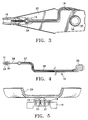
- FIG. 3 shows the slider 15 of a head gimbal assembly 12.
- Head gimbal assembly 12 is composed of a load beam 20, flexure 19, slider 15 and flex circuit 16.
- Slider 15 includes transducer 14 (see Fig. 1) and transducer bonding pad 21 (see Fig. 5) and is connected to flexure 19.
- Flexure 19 is connected to load beam 20 and allows roll and pitch movement of the slider 15.
- Load beam 20 has a mounting ring 23 which is used to connect the head gimbal assembly 12 to arm 11 of actuator 10.
- Load beam 20 and flexure 19 have an alignment hole 24 which is used to align the six head gimbal assemblies 12 with each other with reference to actuator 10.
- Flex circuit 16 is shown being routed from the side of load beam 20 to the center of load beam 20 and then symmetrically along the centerline of load beam 20 and flexure 19 to prevent any biasing of the load beam 20 by flex circuit 16.
- Flex circuit 16 is symmetrically routed around alignment hole 24 to prevent any further biasing of the load beam 20 by flex circuit 16.
- Flex circuit 16 narrows before passing between slider 15 and flexure 19 so as to provide a length of the flex circuit 16 that has low stiffness characteristics. The narrow length of the flex circuit 16 is not bonded to flexure 19 or the load beam 20. Flex circuit 16 is bonded to flexure 19 in the area of alignment hole 24 and to the load beam at various points between alignment hole 24 and mounting ring 23.
- a service loop is formed by the portion of the flex circuit 16 between the point that flex circuit 16 is bonded to flexure 19 in the area of alignment hole 24 and the first point of passage of flex circuit 16 between flexure 19 and slider 15.
- the service loop is therefore located to the rear of the slider 15 and does not have any adverse effects on the flying characteristics if the slider 15.
- FIG. 4 illustrates the flex circuit 16 of the invention.
- Flex circuit 16 has a first area 25 wherein the four conductor are widened and spaced further apart to ease connecting of the four conductors to the bonding pads 18 on wiring terminals 13 on actuator 10.
- the configuration of the four conductor bonding pads in area 25 are designed to mate with the bonding pads 13 configuration of wiring terminals 18 on actuator 10.
- Area 26 of flex circuit 16 is of the length required to extend the four conductors from area 25 to the center line of the load beam 20 of the head gimbal assembly 12 with which the flex circuit 16 is to be used with.
- the size of the conductors may be enlarged in areas 25, 26, 27 and 29 to reduce the line resistance of each of the conductors.
- Area 28 of flex circuit 16 is designed to be symmetrical about the center line of the load beam 20 and/or flexure 19 to minimize any adverse roll and pitch effects the flex circuit 16 may have on the load beam 20 and flexure 16 when bonded to the load beam 20 and/or flexure 16.
- Area 28 of the flex circuit 16 is reduced in width so as to reduce the stiffness of the flex circuit 16 in area 28.
- the stiffness is reduced to minimize the effect of the flex circuit 16 being connected to the slider 15 and to allow the slider 15 to have approximately the same roll and pitch characteristics as the slider 15 would have had if the flex circuit 16 was not attached to the slider 15.
- the stiffness of the area 28 is proportional to the width of area 28 multiplied by the cube of the thickness of area 28 divided by the cube of the length of area 28.
- the thickness of the flex circuit 16 in area 28 has a greater effect on the stiffness than the width of the flex circuit 28.
- the thickness of the flex circuit 16 is bounded by physical restraints to have a minimum thickness range of 1.7 to 2.7 mils. In the manufacture of a flex circuit 16, the thickness of the flex circuit 16 remains constant through all areas of the flex circuit 16. Thus for a given flex circuit 16 the design parameters that can be adjusted are the width and length of the flex circuit 16.
- the bonding of the flex circuit 16 to the load beam and/or flexure advantageously increases the yaw characteristic of the head gimbal assembly thereby allowing a head gimbal assembly using the flex circuit 16 to be used at higher track densities than the same head gimbal assembly using individual wires in a service loop configuration
- Area 29 of flex circuit 16 is enlarged in width and provides that the four conductors be located approximate to the transducer bonding pad 21 on slider 15.
- An opening 30 is provided in flex circuit 16 to allow the physical joining of the slider 15 to the portion of the flexure 19 that allows movement of slider 15. Slider 15, flexure 19 and area 29 of flex circuit 16 will move as a single unit.
- Four conductors 31 are provided at the end of area 28 for bonding to transducer bonding pads 21 on slider 15.
- FIG. 5 illustrates the four conductors 31 of flex circuit 16 being bonded to the four transducer bonding pads 21 on slider 15. Flex circuit 16 is shown as being sandwiched between flexure 19 and slider 15 to form a single movable unit.
Landscapes
- Supporting Of Heads In Record-Carrier Devices (AREA)
- Moving Of Heads (AREA)
Applications Claiming Priority (2)
| Application Number | Priority Date | Filing Date | Title |
|---|---|---|---|
| US53351895A | 1995-09-25 | 1995-09-25 | |
| US533518 | 1995-09-25 |
Publications (1)
| Publication Number | Publication Date |
|---|---|
| EP0764942A1 true EP0764942A1 (fr) | 1997-03-26 |
Family
ID=24126306
Family Applications (1)
| Application Number | Title | Priority Date | Filing Date |
|---|---|---|---|
| EP96115327A Withdrawn EP0764942A1 (fr) | 1995-09-25 | 1996-09-24 | Circuit flexible pour ensemble à tête magnétique avec surface rigidité réduite pour minimiser les effets de tangage et de roulis |
Country Status (3)
| Country | Link |
|---|---|
| US (1) | US5859749A (fr) |
| EP (1) | EP0764942A1 (fr) |
| JP (1) | JPH09167454A (fr) |
Cited By (6)
| Publication number | Priority date | Publication date | Assignee | Title |
|---|---|---|---|---|
| US5883758A (en) * | 1996-08-07 | 1999-03-16 | Hutchinson Technology Incorporated | Lead structure with stainless steel base for attachment to a suspension |
| US5982584A (en) * | 1996-12-19 | 1999-11-09 | Hutchinson Technology Incorporated | Integrated lead suspension flexure with serially arranged metal-backed and suspended insulator portions for hygrothermal compensation |
| US6147839A (en) * | 1996-12-23 | 2000-11-14 | Hutchinson Technology, Inc. | Head suspension with outriggers extending across a spring region |
| US6381100B1 (en) | 1996-12-19 | 2002-04-30 | Hutchinson Technology Incorporated | Integrated lead suspension flexure with balanced parallel leads for insulator layer hygrothermal compensation |
| US6612016B1 (en) | 1997-12-18 | 2003-09-02 | Hutchinson Technology Incorporated | Method of making integrated lead suspension flexure with balanced parallel leads for insulator layer hygrothermal compensation |
| US6765763B2 (en) | 2000-06-16 | 2004-07-20 | Seagate Technology Llc | Actuator system for disc drive |
Families Citing this family (18)
| Publication number | Priority date | Publication date | Assignee | Title |
|---|---|---|---|---|
| KR950020658A (ko) * | 1993-12-07 | 1995-07-24 | 새끼자와 다다시 | 자기디스크장치 |
| JPH08203030A (ja) * | 1995-01-25 | 1996-08-09 | Sony Corp | 磁気ヘッド装置及びその製造方法 |
| US6202288B1 (en) | 1997-12-26 | 2001-03-20 | Tdk Corporation | Method for manufacturing magnetic head suspension assembly with head IC chip |
| JPH11195214A (ja) * | 1997-12-26 | 1999-07-21 | Tdk Corp | 磁気ヘッド装置の製造方法 |
| US6399889B1 (en) | 1998-09-14 | 2002-06-04 | Seagate Technology Llc | Head interconnect circuit with alignment finger |
| US7191512B2 (en) * | 1998-09-29 | 2007-03-20 | Applied Kinetics, Inc. | Tray system for holding and positioning components |
| US6266869B1 (en) | 1999-02-17 | 2001-07-31 | Applied Kinetics, Inc. | Method for assembling components |
| US7127799B2 (en) * | 1998-10-02 | 2006-10-31 | Applied Kinetics, Inc. | Head gimbal assembly method |
| WO2000030081A1 (fr) * | 1998-11-13 | 2000-05-25 | Tdk Corporation | Mecanisme de support de tete d'enregistrement/lecture et appareil d'enregistrement/lecture |
| US6154343A (en) * | 1998-12-18 | 2000-11-28 | Magnecomp Corp. | Suspension manufacturing method and product |
| US6278585B1 (en) | 1999-04-19 | 2001-08-21 | International Business Machines Corporation | Transducer suspension termination system |
| US6636383B1 (en) * | 2000-03-17 | 2003-10-21 | Maxtor Corporation | Disk drive actuator arm assembly with unitary flex cable |
| JP2001266511A (ja) * | 2000-03-24 | 2001-09-28 | Toshiba Corp | ヘッドサスペンションアッセンブリ、およびヘッドサスペンションアッセンブリを備えた磁気ディスク装置 |
| US6522504B1 (en) * | 2001-01-31 | 2003-02-18 | Western Digital Technologies, Inc. | Head stack assembly and disk drive using a reversed direction head gimbal assembly |
| US7027141B2 (en) * | 2001-05-03 | 2006-04-11 | Applied Kinetics, Inc. | Static attitude determination and adjust of head suspension components |
| KR100438777B1 (ko) * | 2001-11-06 | 2004-07-05 | 삼성전자주식회사 | 공동이 형성된 가요성 인쇄회로를 구비하는 하드디스크드라이브 |
| US7593194B2 (en) * | 2004-11-30 | 2009-09-22 | International Business Machines Corporation | Tape recording head promoting lateral motion |
| US20100214697A1 (en) * | 2007-07-05 | 2010-08-26 | Minggao Yao | Suspension design for high shock performance soldering ball bonding |
Citations (5)
| Publication number | Priority date | Publication date | Assignee | Title |
|---|---|---|---|---|
| JPS62217476A (ja) * | 1985-10-28 | 1987-09-24 | Hitachi Ltd | 磁気ヘツドアセンブリ |
| EP0434261A1 (fr) * | 1989-12-22 | 1991-06-26 | Seagate Technology International | Dispositif pour maintenir une gaine de conducteur dans un assemblage avec suspension de tête à cardan |
| WO1993017416A1 (fr) * | 1992-02-27 | 1993-09-02 | Hutchinson Technology Incorporated | Suspension a la cardan pour systemes de suspension de tete magnetique |
| WO1994016438A1 (fr) * | 1993-01-07 | 1994-07-21 | Hutchinson Technology Incorporated | Structure a cardan amelioree de transducteur |
| JPH0831127A (ja) * | 1994-07-07 | 1996-02-02 | Nec Corp | 磁気ヘッド装置 |
Family Cites Families (7)
| Publication number | Priority date | Publication date | Assignee | Title |
|---|---|---|---|---|
| US4379316A (en) * | 1981-06-11 | 1983-04-05 | Siemens Corporation | Read/write head carriage assembly for a floppy disk drive |
| JPS6119083A (ja) * | 1984-07-05 | 1986-01-27 | キヤノン電子株式会社 | 導電部材 |
| US4811143A (en) * | 1986-03-31 | 1989-03-07 | Kabushiki Kaisha Toshiba | Head supporting mechanism for maintaining close operative relationship between magnetic heads and a flexible disk |
| US4819094A (en) * | 1986-08-12 | 1989-04-04 | Oberg Gary R | Damped magnetic head suspension assembly |
| US5185683A (en) * | 1987-12-21 | 1993-02-09 | Hutchinson Technology, Inc. | Suspension arm mounting assembly |
| JP2616631B2 (ja) * | 1992-04-23 | 1997-06-04 | 日本電気株式会社 | 磁気ヘッド |
| JP2935802B2 (ja) * | 1993-12-09 | 1999-08-16 | アルプス電気株式会社 | 浮上式磁気ヘッド装置 |
-
1996
- 1996-09-24 EP EP96115327A patent/EP0764942A1/fr not_active Withdrawn
- 1996-09-25 JP JP8252846A patent/JPH09167454A/ja active Pending
-
1997
- 1997-04-14 US US08/840,260 patent/US5859749A/en not_active Expired - Lifetime
Patent Citations (5)
| Publication number | Priority date | Publication date | Assignee | Title |
|---|---|---|---|---|
| JPS62217476A (ja) * | 1985-10-28 | 1987-09-24 | Hitachi Ltd | 磁気ヘツドアセンブリ |
| EP0434261A1 (fr) * | 1989-12-22 | 1991-06-26 | Seagate Technology International | Dispositif pour maintenir une gaine de conducteur dans un assemblage avec suspension de tête à cardan |
| WO1993017416A1 (fr) * | 1992-02-27 | 1993-09-02 | Hutchinson Technology Incorporated | Suspension a la cardan pour systemes de suspension de tete magnetique |
| WO1994016438A1 (fr) * | 1993-01-07 | 1994-07-21 | Hutchinson Technology Incorporated | Structure a cardan amelioree de transducteur |
| JPH0831127A (ja) * | 1994-07-07 | 1996-02-02 | Nec Corp | 磁気ヘッド装置 |
Non-Patent Citations (2)
| Title |
|---|
| PATENT ABSTRACTS OF JAPAN vol. 12, no. 79 (P - 676) 12 March 1988 (1988-03-12) * |
| PATENT ABSTRACTS OF JAPAN vol. 96, no. 9 28 June 1996 (1996-06-28) * |
Cited By (7)
| Publication number | Priority date | Publication date | Assignee | Title |
|---|---|---|---|---|
| US5883758A (en) * | 1996-08-07 | 1999-03-16 | Hutchinson Technology Incorporated | Lead structure with stainless steel base for attachment to a suspension |
| US5982584A (en) * | 1996-12-19 | 1999-11-09 | Hutchinson Technology Incorporated | Integrated lead suspension flexure with serially arranged metal-backed and suspended insulator portions for hygrothermal compensation |
| US6381100B1 (en) | 1996-12-19 | 2002-04-30 | Hutchinson Technology Incorporated | Integrated lead suspension flexure with balanced parallel leads for insulator layer hygrothermal compensation |
| US6147839A (en) * | 1996-12-23 | 2000-11-14 | Hutchinson Technology, Inc. | Head suspension with outriggers extending across a spring region |
| US6612016B1 (en) | 1997-12-18 | 2003-09-02 | Hutchinson Technology Incorporated | Method of making integrated lead suspension flexure with balanced parallel leads for insulator layer hygrothermal compensation |
| US6765763B2 (en) | 2000-06-16 | 2004-07-20 | Seagate Technology Llc | Actuator system for disc drive |
| SG165146A1 (en) * | 2000-06-16 | 2010-10-28 | Seagate Technology Llc | Actuator system for disc drive |
Also Published As
| Publication number | Publication date |
|---|---|
| JPH09167454A (ja) | 1997-06-24 |
| US5859749A (en) | 1999-01-12 |
Similar Documents
| Publication | Publication Date | Title |
|---|---|---|
| US5859749A (en) | Flexible circuit for magnetic head assembly | |
| US5956209A (en) | Integrated suspension flexure having a compliant tip termination platform | |
| EP1174860B1 (fr) | Mécanisme de support de tête magnétique | |
| US6275358B1 (en) | Conductor trace array having passive stub conductors | |
| US5986853A (en) | Transducer suspension system | |
| US5995328A (en) | Multi-layered integrated conductor trace array interconnect structure having optimized electrical parameters | |
| EP0834867B1 (fr) | Suspension avec réseau de trace multicouche conductrice intégré pour paramètres électriques optimisés | |
| US6125014A (en) | Via-less connection using interconnect traces between bond pads and a transducer coil of a magnetic head slider | |
| US7006330B1 (en) | Head stack assembly including a ground conductive pad for grounding a slider to a gimbal | |
| KR100288806B1 (ko) | 데이터기록디스크드라이브용일체형헤드-전자장치상호접속서스펜션 | |
| US7113372B2 (en) | HGA plateau gimbal design | |
| US7110222B2 (en) | System and apparatus for assembling hard disk drive integrated lead suspensions to arm electronics cables via additional degrees of freedom at the tail termination and impedance grooming thereof | |
| JPH06168414A (ja) | 薄膜磁気ヘッド変換器及び懸架部の組合せシステム並びにその製造方法 | |
| US3323116A (en) | Electromagnetic transducer and method of fabrication | |
| US5835306A (en) | Integrated gimbal suspension assembly with assymetric bond pad | |
| JP2001501762A (ja) | 一体型高コンプライアンスジンバルを備えるフレックス回路フレクシャ | |
| US6219202B1 (en) | Slider suspension assembly and method for attaching a slider to a suspension in a data-recording disk file including a flexible integrated cable having an aperture therein for permitting electrical contact | |
| US6747849B1 (en) | High performance suspension with reduced flow-induced vibration | |
| CA2221966A1 (fr) | Suspension avec conducteur integre a capacite reglable | |
| US20030128474A1 (en) | Low electrical impedance slider grounding | |
| US5771138A (en) | Head gimbal assembly with transducer wires attached at two points to slider | |
| JPH05282642A (ja) | 磁気ディスク装置 | |
| KR20020072247A (ko) | 집적된 충전 블리드 저항기를 구비하는 자기 변환기 | |
| US6411469B1 (en) | Transducer suspension system with high conductivity leads having two layers | |
| JP2894262B2 (ja) | サスペンション装置、スライダ−サスペンションアセンブリ及びアセンブリキャリッジ装置 |
Legal Events
| Date | Code | Title | Description |
|---|---|---|---|
| PUAI | Public reference made under article 153(3) epc to a published international application that has entered the european phase |
Free format text: ORIGINAL CODE: 0009012 |
|
| AK | Designated contracting states |
Kind code of ref document: A1 Designated state(s): DE NL |
|
| 17P | Request for examination filed |
Effective date: 19970716 |
|
| 17Q | First examination report despatched |
Effective date: 20000426 |
|
| STAA | Information on the status of an ep patent application or granted ep patent |
Free format text: STATUS: THE APPLICATION IS DEEMED TO BE WITHDRAWN |
|
| 18D | Application deemed to be withdrawn |
Effective date: 20000907 |