EP0765108A2 - Dispositif pour alimenter une lampe à forte décharge - Google Patents
Dispositif pour alimenter une lampe à forte décharge Download PDFInfo
- Publication number
- EP0765108A2 EP0765108A2 EP96306840A EP96306840A EP0765108A2 EP 0765108 A2 EP0765108 A2 EP 0765108A2 EP 96306840 A EP96306840 A EP 96306840A EP 96306840 A EP96306840 A EP 96306840A EP 0765108 A2 EP0765108 A2 EP 0765108A2
- Authority
- EP
- European Patent Office
- Prior art keywords
- inverter
- high intensity
- lamp
- lighting device
- intensity discharge
- Prior art date
- Legal status (The legal status is an assumption and is not a legal conclusion. Google has not performed a legal analysis and makes no representation as to the accuracy of the status listed.)
- Granted
Links
Images


Classifications
-
- H—ELECTRICITY
- H05—ELECTRIC TECHNIQUES NOT OTHERWISE PROVIDED FOR
- H05B—ELECTRIC HEATING; ELECTRIC LIGHT SOURCES NOT OTHERWISE PROVIDED FOR; CIRCUIT ARRANGEMENTS FOR ELECTRIC LIGHT SOURCES, IN GENERAL
- H05B41/00—Circuit arrangements or apparatus for igniting or operating discharge lamps
- H05B41/14—Circuit arrangements
- H05B41/26—Circuit arrangements in which the lamp is fed by power derived from DC by means of a converter, e.g. by high-voltage DC
- H05B41/28—Circuit arrangements in which the lamp is fed by power derived from DC by means of a converter, e.g. by high-voltage DC using static converters
- H05B41/288—Circuit arrangements in which the lamp is fed by power derived from DC by means of a converter, e.g. by high-voltage DC using static converters with semiconductor devices and specially adapted for lamps without preheating electrodes, e.g. for high-intensity discharge lamps, high-pressure mercury or sodium lamps or low-pressure sodium lamps
- H05B41/2885—Static converters especially adapted therefor; Control thereof
- H05B41/2886—Static converters especially adapted therefor; Control thereof comprising a controllable preconditioner, e.g. a booster
-
- H—ELECTRICITY
- H05—ELECTRIC TECHNIQUES NOT OTHERWISE PROVIDED FOR
- H05B—ELECTRIC HEATING; ELECTRIC LIGHT SOURCES NOT OTHERWISE PROVIDED FOR; CIRCUIT ARRANGEMENTS FOR ELECTRIC LIGHT SOURCES, IN GENERAL
- H05B41/00—Circuit arrangements or apparatus for igniting or operating discharge lamps
- H05B41/14—Circuit arrangements
- H05B41/26—Circuit arrangements in which the lamp is fed by power derived from DC by means of a converter, e.g. by high-voltage DC
- H05B41/28—Circuit arrangements in which the lamp is fed by power derived from DC by means of a converter, e.g. by high-voltage DC using static converters
- H05B41/288—Circuit arrangements in which the lamp is fed by power derived from DC by means of a converter, e.g. by high-voltage DC using static converters with semiconductor devices and specially adapted for lamps without preheating electrodes, e.g. for high-intensity discharge lamps, high-pressure mercury or sodium lamps or low-pressure sodium lamps
- H05B41/2881—Load circuits; Control thereof
- H05B41/2882—Load circuits; Control thereof the control resulting from an action on the static converter
- H05B41/2883—Load circuits; Control thereof the control resulting from an action on the static converter the controlled element being a DC/AC converter in the final stage, e.g. by harmonic mode starting
-
- H—ELECTRICITY
- H05—ELECTRIC TECHNIQUES NOT OTHERWISE PROVIDED FOR
- H05B—ELECTRIC HEATING; ELECTRIC LIGHT SOURCES NOT OTHERWISE PROVIDED FOR; CIRCUIT ARRANGEMENTS FOR ELECTRIC LIGHT SOURCES, IN GENERAL
- H05B41/00—Circuit arrangements or apparatus for igniting or operating discharge lamps
- H05B41/14—Circuit arrangements
- H05B41/26—Circuit arrangements in which the lamp is fed by power derived from DC by means of a converter, e.g. by high-voltage DC
- H05B41/28—Circuit arrangements in which the lamp is fed by power derived from DC by means of a converter, e.g. by high-voltage DC using static converters
- H05B41/288—Circuit arrangements in which the lamp is fed by power derived from DC by means of a converter, e.g. by high-voltage DC using static converters with semiconductor devices and specially adapted for lamps without preheating electrodes, e.g. for high-intensity discharge lamps, high-pressure mercury or sodium lamps or low-pressure sodium lamps
- H05B41/2885—Static converters especially adapted therefor; Control thereof
- H05B41/2887—Static converters especially adapted therefor; Control thereof characterised by a controllable bridge in the final stage
-
- Y—GENERAL TAGGING OF NEW TECHNOLOGICAL DEVELOPMENTS; GENERAL TAGGING OF CROSS-SECTIONAL TECHNOLOGIES SPANNING OVER SEVERAL SECTIONS OF THE IPC; TECHNICAL SUBJECTS COVERED BY FORMER USPC CROSS-REFERENCE ART COLLECTIONS [XRACs] AND DIGESTS
- Y02—TECHNOLOGIES OR APPLICATIONS FOR MITIGATION OR ADAPTATION AGAINST CLIMATE CHANGE
- Y02B—CLIMATE CHANGE MITIGATION TECHNOLOGIES RELATED TO BUILDINGS, e.g. HOUSING, HOUSE APPLIANCES OR RELATED END-USER APPLICATIONS
- Y02B20/00—Energy efficient lighting technologies, e.g. halogen lamps or gas discharge lamps
-
- Y—GENERAL TAGGING OF NEW TECHNOLOGICAL DEVELOPMENTS; GENERAL TAGGING OF CROSS-SECTIONAL TECHNOLOGIES SPANNING OVER SEVERAL SECTIONS OF THE IPC; TECHNICAL SUBJECTS COVERED BY FORMER USPC CROSS-REFERENCE ART COLLECTIONS [XRACs] AND DIGESTS
- Y10—TECHNICAL SUBJECTS COVERED BY FORMER USPC
- Y10S—TECHNICAL SUBJECTS COVERED BY FORMER USPC CROSS-REFERENCE ART COLLECTIONS [XRACs] AND DIGESTS
- Y10S315/00—Electric lamp and discharge devices: systems
- Y10S315/07—Starting and control circuits for gas discharge lamp using transistors
Definitions
- the present invention relates to a high intensity discharge lamp lighting device to light a high intensity discharge lamp.
- the high intensity discharge lamp lighting device is used for lighting a high intensity discharge lamp such as a lamp for projector.
- Fig. 4 shows a circuit diagram for a conventional high intensity discharge lamp lighting device using a high power-factor inverter.
- a power-frequency AC power is rectified to a direct current by a rectifier including diodes D101 - D104, an inductor LF, and a condenser CF, and the output is applied to a booster chopper mode sine wave converter including a choke coil L101 , a switching element SW1, a diode D105, and a condenser C.
- the booster chopper mode sine wave converter is connected to a full- bridge mode inverter INV as the load.
- the booster chopper mode sine wave converter will briefly be explained.
- a voltage ei' is detected by resisters R101, R102 to be fed to a multiplier MP1. This voltage is transferred to a current command reference Ii* having the same wave form as the voltage ei'.
- a current Ii' is detected by a resister R104 and a comparator COMP1 compares Ii' to Ii* to produce a PWM signal proportional to the difference between Ii* and Ii'.
- a lamp current detecting resister R105 detects a lamp current IL
- a variation ⁇ IL of the lamp current IL is obtained by a constant-current circuit
- the multiplier MP1 makes a product by ⁇ IL and ei' to produce the current command reference Ii*.
- a feedback circuit is configured, the amplitude of Ii* varies according to the variation of IL, i.e, ⁇ IL, thereby IL is stabilized and at the same time the current waveform identical to ei' can be obtained.
- the average current by each switching is proportional to the input voltage, removing higher harmonics of the switching wave form by means of a low pass filter consisting of an inductor LF and a condenser CF makes the wave form of the input current analog to the input voltage with regard to one cycle of the AC line as shown in Fig. 5, and the power factor becomes almost 1.
- the booster chopper mode sine wave converter is connected to the full- bridge mode inverter INV as the load.
- TR1 - TR4 are switching transistors configuring the inverter INV.
- the output of the inverter INV is connected to the secondary coil of a transformer T101 and a halide lamp L (HID, hereinafter) in series.
- a timer circuit TM is activated to feed a 100Hz starting trigger pulse to a starting pulse generator PG.
- the starting pulse generator PG feeds a starting pulse for about five seconds, and the starting pulse is boosted to 3 - 5 KV by a transformer T101.
- the timer circuit TM feeds an inverter starting signal to a oscillator OSC, thereby the oscillator OSC starts operation, whose output activates a drive circuit DCC; which in consequence activates the inverter INV.
- the HID lamp L enters in a lighting state, transferring the state from a glow discharge to an arc discharge.
- the inverter current i.e., the lamp current is detected by the lamp current detecting resister R105, which is fed to a control IC.
- the control IC feeds a signal to a DRIVE CIRCUIT as the control input terminal of the booster chopper mode sine wave converter so as to suppress the lamp current if it goes high and to increase the lamp current if it goes low, thus controlling the inverter INV into a constant current.
- the output voltage of the booster chopper mode sine wave converter decreases by the PWM operation of the booster chopper mode sine wave converter, which maintains the constant current operation.
- the foregoing conventional inverter is well known that it has restrictions for a smaller size.
- the lamp current will fade out to lead the lamp to an unstable operation due to the acoustic resonance effect if the inverter INV oscillating frequency is less than 300 KHz. Therefore, the switching frequency is selected to less than some 100 Hz not inducing the acoustic resonance.
- the switching frequency is apt to be less than 400 Hz due to the restriction of the switching elements such as the switching speed, thereby the transformer T1 is difficult to be made smaller.
- control circuit and drive circuit of the full-bridge mode inverter are complicated and costly.
- the present invention provides the high intensity discharge lamp lighting device described hereafter.
- the high intensity discharge lamp lighting device includes a rectifier for a power-frequency power supply, a booster chopper mode sine wave converter, a zero volt switching push pull inverter, and a high intensity lamp of a halide lamp. And, as a starting device for the halide lamp, the high intensity discharge lamp lighting device generates a high voltage (5 KV) using a resonance by a ballast choke for the inverter and a condenser connected in parallel to the halide lamp, thereby inducing a glow discharge. And, a PFM (pulse frequency modulation) circuit controls the lamp current of the halide lamp to keep it constant.
- a PFM pulse frequency modulation
- a re-lighting circuit after lighting works such that the control IC stops operation by a pulse-by-pulse mode current limiter of an inverter control IC, thereafter a soft starting circuit operates to generate a high voltage on the output of the inverter; when the lamp temperature is so high that the mercury vapor pressure inside the tube goes high and lighting cannot be started, the foregoing operation is repeated to achieve re-lighting.
- the resonance by the ballast choke and the condenser connected in parallel to the halide lamp generates a high voltage (5 KV) to the output of the inverter, leading to a glow discharge.
- the operation of the inverter became a blocking oscillation mode; consequently, the inverter generates a high voltage periodically until the halide lamp starts lighting.
- the re-lighting circuit can be constructed with a simplified one.
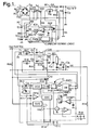
- Fig. 1 is a circuit block diagram showing one embodiment of the present invention.
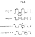
- Fig. 2 is a wave form chart showing a driver output signal and output wave form of a power switching element.
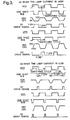
- Fig. 3 is a wave form chart showing wave forms of the parts of the high intensity discharge lamp lighting device dividing into the case of a small lamp current and a large current.
- Fig. 4 is a circuit block diagram showing a conventional high intensity discharge lamp lighting device.
- Fig. 5 is a wave form chart showing wave forms of the input voltage and the current of the converter.
- Fig.1 is a circuit diagram showing a high intensity discharge lamp lighting device according to the present invention.
- the power-frequency AC power supply is rectified by a rectifier consisting of diodes D1 - D4 into a direct current, and the output is applied to a booster chopper modesine wave converter including a choke coil L2, a power MOSFET Q2, a diode D5, and a condenser C2.
- the booster chopper mode sine wave converter is connected to a voltage resonant inverter as the load.
- the booster chopper mode sine wave converter will briefly be described.
- a voltage ei' is detected by resisters R8, R9 to be fed to a multiplier MULT. This voltage is multiplied by an output of an error amplifier to produce the output of the multiplier MULT.
- a current running through the choke coil L2 is detected by a resistor R3, and the voltage across the resistor R3 is distributed to a current sense logic circuit. If this voltage exceeds a nominal voltage determined by the output VMO of the multiplier MULT, the PWM goes OFF; consequently, the gate of the power MOSFET Q2 turns OFF.
- an output of a current detecting winding Ns2 of the choke coil L2 is fed to the current sense logic circuit through a resistor R6.
- a resistor R7 is a starting resistor.
- a resistor R1 is a gate drive resistor for the power switching element Q2, a diode D6 is to pull down charges stored between the gate and the source of the power switching element Q2. Since the output voltage of the booster chopper mode sine wave converter is made constant, the input voltage of the zero volt switching push pull inverter connected as the load becomes constant; and usually the halide lamp is used without adjusting intensity (at a constant lamp current), the lamp power is controlled constant, and the switching frequency of the inverter becomes constant.
- L1 is a ballast choke having a primary coil npl and a secondary coil ns2, of the zero volt switching push pull inverter.
- IC1 is a zero volt switching power supply controller composed of an integrated circuit. This IC1 is available on the market, for example, Micro Linear ML4816.
- Q1, Q3 are power switching elements (power MOSFET).
- a resistor R20 is a starting resistor, when the system is powered, the zero volt switching power supply controller IC1 is supplied with power to operate.
- This zero volt switching power supply controller IC1 includes a voltage controlled oscillator VCO, one-shot multi-vibrator MV, pulse frequency modulator PFM, driver DB, soft start controller SSC, comparator COMP1, COMP2, flip flop FF1, constant current source IS, error amplifier OPA, and reference voltage generator 5VG for generating a 5 Volt reference voltage VREF.
- the output A, B of the driver DB operate complimentary.
- the output A and B of the driver DB drive the power switching element Q1 and Q3, respectively.
- Fig. 2 illustrates the operational timing chart. The connecting point of the source of the power switching element Q1 with the drain of the Q3, i.
- the output of the inverter is connected in series to a DC decoupling condenser C20 connecting in series with the ballast choke L1 .
- a starting condenser C5 is connected between the output of the ballast choke L1 and the ground.
- the foregoing condenser C5 is connected in parallel to a halide lamp L connecting in series with a current detecting condenser C7.
- the operation of the embodiment according to the present invention will now be described.
- the HID lamp L does not light, and since the current does not flow through this lamp L, the voltage across the current detecting condenser 7 is 0 V.
- a voltage is applied across the current detecting condenser C7, and this voltage is rectified by a diode D8 and condenser C8 to be fed to a control input of the control IC.
- a condenser 11 is charged through a resistor 14 and the voltage across the condenser 11 increases.
- the condenser 11 is connected to the soft start controller SSC.
- the output of the soft start controller SSC is in HIGH level directly after the power turning ON. Since the output is connected to the control input of the voltage controlled oscillator VCO, the output of the voltage controlled oscillator VCO goes higher than that in the steady state operation. As the voltage across the condenser C11 increases, the output of the soft start controller SSC is designed to decrease; and the oscillating frequency of the voltage controlled oscillator VCO gradually lowers. When the voltage across the condenser C11 goes down to less than the threshold voltage Vth, the output of the soft start controller SSC goes into an open state and the voltage controlled oscillator VCO is controlled only by the output of the error amplifier OPA. Namely, when the Ac power is turned ON, the voltage controlled oscillator VCO starts operation at a higher frequency than that in the steady state operation; and therefore, the current stress in the power switching elements Q1, Q3 and the ballast choke L1 can be restrained lower.
- the method of starting the HID lamp will be described. Immediately after the AC power is supplied, the HID lamp L is not lighted and the internal impedance of the lamp is high. Selecting the value of the ballast choke L1 and the starting condenser C5 so as to set the resonance frequency by these two components to, for example, 300 KHz will produce a high voltage (5 KV) of a 300 KHz sine wave across the condenser C5, thereby starting a glow discharge in the HID lamp L.
- the choke coil L1 is a ballast inductor loaded with the voltage difference between the output (connecting point of the source of the power switching element Q1 and the drain of the power switching element Q3) voltage of the inverter and the discharge maintaining voltage.
- R17, R18 are gate drive resistors for the power switching elements Q1, Q3; D9, D10 are to pull down charges stored between the gate and the source of the power switching element Q1 and Q3, respectively.
- a diode 11 and a condenser 13 forms a rectifier for the power supply to the zero volt switching power supply controller IC1.
- R20 is a starting resistor.
- the zero volt switching power supply controller IC1 will be described in detail with reference to Fig. 1 and 3.
- the discharge current (lamp current) of the HID lamp L is increased by any reason, the output of the error amplifier OPA increases and the oscillating frequency of the voltage controlled oscillator VCO goes high.
- the fall of output of the voltage controlled oscillator VCO puts the one-shot MB of the one-shot multi-vibrator MB into the set state, the output of which goes HIGH level.
- the fall of the phase-reversed output voltage controlled oscillator (bar) of the voltage controlled oscillator VCO puts the one-shot MB (bar) of the one-shot multi-vibrator into the set state, the output of which goes HIGH level.
- a resistor R12 and a condenser C12 are to determine the pulse width of the output of the one-shot multi-vibrator, and the output of the one-shot MB is maintained in a high level during the time Toff determined by the time constant. That is, with maintaining the Toff constant, pulse frequency control is performed which varies the oscillating frequency (i.e., switching frequency) of the voltage controlled oscillator VCO.
- a condenser C8 and a resistor R10 are to determine an oscillating frequency of the voltage controlled oscillator VCO.
- a resistor R11 and a condenser C9 is for phase compensation of the error amplifier OPA.
- a transformer T1 is for gate drive of the power switching element Q1.
- the output of the comparator COMP1 becomes a high level to put the flip flop FF1 into a set state.
- the output of the flip flop FF1 controls the constant current source IS to turn ON and OFF, and the constant current source IS charges a condenser C10.
- the flip flop FF1 is reset every one cycle of the oscillating frequency. If the power switching element Q3 continues to flow an excessive current, the voltage across the condenser C10 goes high.
- the condenser C10 is connected to the +input of the comparator COMP2, when the voltage exceeds the threshold voltage 3.2 V of the comparator COMP2, COMP2 becomes a high level; closing AND gate, AND1, and AND2 leads the output of the driver DB to a low level.
- the oscillation stops, and the power supply voltage to the control IC IC1 lowers.
- IC1 starts operation by the starting resistor R20, the foregoing operation is repeated. That is, it starts a blocking oscillation mode. In this state, the temperature inside the tube of the HID lamp L falls, mercury vapor pressure lowers to increase the internal resistance, thus maintaining the state to finally enabling a glow discharge.
- a power MOSFET having a lower withstand voltage having a lower ON resistance
- a simplified starting circuit can be configured using a ballast choke and a condenser.
- the switching frequency of the inverter can be made constant, thereby reducing interference to other equipment.
Landscapes
- Engineering & Computer Science (AREA)
- Power Engineering (AREA)
- Circuit Arrangements For Discharge Lamps (AREA)
Applications Claiming Priority (3)
| Application Number | Priority Date | Filing Date | Title |
|---|---|---|---|
| JP26629695 | 1995-09-20 | ||
| JP7266296A JPH0992483A (ja) | 1995-09-20 | 1995-09-20 | 高輝度放電灯点灯装置 |
| JP266296/95 | 1995-09-20 |
Publications (3)
| Publication Number | Publication Date |
|---|---|
| EP0765108A2 true EP0765108A2 (fr) | 1997-03-26 |
| EP0765108A3 EP0765108A3 (fr) | 1998-03-25 |
| EP0765108B1 EP0765108B1 (fr) | 2005-06-29 |
Family
ID=17428980
Family Applications (1)
| Application Number | Title | Priority Date | Filing Date |
|---|---|---|---|
| EP96306840A Expired - Lifetime EP0765108B1 (fr) | 1995-09-20 | 1996-09-20 | Dispositif pour alimenter une lampe à forte décharge |
Country Status (4)
| Country | Link |
|---|---|
| US (1) | US6069458A (fr) |
| EP (1) | EP0765108B1 (fr) |
| JP (1) | JPH0992483A (fr) |
| DE (1) | DE69634892T2 (fr) |
Cited By (12)
| Publication number | Priority date | Publication date | Assignee | Title |
|---|---|---|---|---|
| FR2794334A1 (fr) * | 1999-05-26 | 2000-12-01 | Matsushita Electric Works Ltd | Ballast pour lampe a decharge comportant un convertisseur de tension |
| EP0979026A3 (fr) * | 1998-08-07 | 2001-05-16 | Sunflower di Dalla Zanna Gianluca | Ballast électronique en particulier pour lampes à haute pression et tubes au néon |
| EP1128709A1 (fr) * | 2000-02-01 | 2001-08-29 | General Electric Company | Control de puissance de ballast pour lampe céramique à halogénure métallique |
| US6404140B1 (en) | 2000-02-01 | 2002-06-11 | General Electri Company | High frequency electronic ballast for ceramic metal halide lamp |
| EP1178710A4 (fr) * | 2000-02-14 | 2005-04-13 | Mitsubishi Electric Corp | Starter de lampe a decharge electrique et systeme d'eclairage |
| EP1499166A3 (fr) * | 2003-07-18 | 2006-01-25 | Minebea Co., Ltd. | Onduleur pour lampes à décharge avec élévateur de tension pour alimenter le circuit d'attaque de grille des interrupteurs de l'onduleur |
| WO2011007207A1 (fr) * | 2009-07-16 | 2011-01-20 | Freescale Semiconductor, Inc. | Circuit intégré comprenant une circuiterie de modulation de tension et procédé correspondant |
| CN104105275A (zh) * | 2013-04-15 | 2014-10-15 | 阮小青 | 太阳能电源双推注锁功率合成卤钨灯 |
| CN104105279A (zh) * | 2013-04-15 | 2014-10-15 | 张根清 | 太阳能电源注锁功率合成双卤素灯 |
| CN104105322A (zh) * | 2013-04-15 | 2014-10-15 | 阮雪芬 | 双半桥注入锁相功率合成荧光灯 |
| CN104105279B (zh) * | 2013-04-15 | 2016-11-30 | 张根清 | 太阳能电源注锁功率合成双卤素灯 |
| CN104105317B (zh) * | 2013-04-15 | 2016-12-28 | 张妙娟 | 直流低电压双推注入锁相功率合成高压钠灯 |
Families Citing this family (22)
| Publication number | Priority date | Publication date | Assignee | Title |
|---|---|---|---|---|
| JP3611800B2 (ja) * | 2001-04-09 | 2005-01-19 | 株式会社小糸製作所 | インバータ装置 |
| CN100592839C (zh) * | 2002-01-15 | 2010-02-24 | 皇家飞利浦电子股份有限公司 | 操作放电灯的设备和方法 |
| KR101025173B1 (ko) * | 2002-07-22 | 2011-03-31 | 코닌클리케 필립스 일렉트로닉스 엔.브이. | 가스 방전 램프를 위한 드라이버와 전류를 감지하고 출력 신호를 생성하기 위한 검출기 |
| JP4244893B2 (ja) | 2004-09-14 | 2009-03-25 | セイコーエプソン株式会社 | 周波数制御による放電ランプの点灯 |
| US7936152B2 (en) * | 2007-07-09 | 2011-05-03 | Fuji Electric Systems Co., Ltd. | Switching power source |
| EP2208402B1 (fr) * | 2007-11-05 | 2013-06-26 | Tridonic GmbH & Co KG | Ballast pour lampe à décharge, par exemple pour une lampe dhi |
| JP2011505659A (ja) * | 2007-11-29 | 2011-02-24 | コーニンクレッカ フィリップス エレクトロニクス エヌ ヴィ | ガス放電ランプを点火する方法及び点火装置 |
| US8488342B2 (en) | 2008-10-21 | 2013-07-16 | On-Bright Electronics (Shanghai) Co., Ltd. | Systems and methods for constant voltage mode and constant current mode in flyback power converters with primary-side sensing and regulation |
| CN102769383B (zh) | 2011-05-05 | 2015-02-04 | 广州昂宝电子有限公司 | 用于利用初级侧感测和调整进行恒流控制的系统和方法 |
| CN102238793B (zh) * | 2011-07-18 | 2014-04-16 | 台达电子企业管理(上海)有限公司 | 高强度气体放电灯控制电路及控制方法 |
| CN105246194B (zh) | 2011-11-15 | 2018-07-03 | 昂宝电子(上海)有限公司 | 用于各种操作模式中的恒流控制的led照明系统和方法 |
| CN102612238B (zh) * | 2012-03-26 | 2015-01-14 | 上海信耀电子有限公司 | 基于dsp的hid镇流器 |
| CN103368400B (zh) | 2012-03-31 | 2015-02-18 | 昂宝电子(上海)有限公司 | 用于恒压控制和恒流控制的系统和方法 |
| CN102790531B (zh) | 2012-07-24 | 2015-05-27 | 昂宝电子(上海)有限公司 | 用于电源变换系统的电流控制的系统 |
| CN104105286B (zh) * | 2013-04-15 | 2016-08-10 | 阮小青 | 直流低压电源注锁功率合成调光无极灯 |
| CN104105311B (zh) * | 2013-04-15 | 2016-08-17 | 阮雪芬 | 直流低压电源注锁功率合成高压钠灯 |
| CN103956900B (zh) | 2014-04-23 | 2017-08-11 | 广州昂宝电子有限公司 | 用于电源变换系统中的输出电流调节的系统和方法 |
| US9812968B2 (en) | 2014-11-19 | 2017-11-07 | Futurewei Technologies, Inc. | Zero voltage switching detection apparatus and method |
| CN107218176B (zh) | 2016-03-21 | 2020-05-19 | 通用电气公司 | 风力节距调整系统 |
| WO2019125205A1 (fr) * | 2017-12-22 | 2019-06-27 | Аркадий Анатольевич СТЕПАНОВ | Source autonome d'alimentation électrique avec sortie haute tension |
| CN116208011A (zh) * | 2022-11-28 | 2023-06-02 | 珠海格力电器股份有限公司 | 一种辉光放电电源电路控制方法、系统、装置及存储介质 |
| CN116111809A (zh) * | 2022-12-09 | 2023-05-12 | 珠海格力电器股份有限公司 | 一种用于空气辉光放电的电源及空气辉光放电控制方法 |
Family Cites Families (8)
| Publication number | Priority date | Publication date | Assignee | Title |
|---|---|---|---|---|
| US3691450A (en) * | 1971-06-14 | 1972-09-12 | Gulton Ind Inc | Power inverter oscillator circuit |
| US4277728A (en) * | 1978-05-08 | 1981-07-07 | Stevens Luminoptics | Power supply for a high intensity discharge or fluorescent lamp |
| US4415839A (en) * | 1981-11-23 | 1983-11-15 | Lesea Ronald A | Electronic ballast for gaseous discharge lamps |
| US4585974A (en) * | 1983-01-03 | 1986-04-29 | North American Philips Corporation | Varible frequency current control device for discharge lamps |
| NL8900703A (nl) * | 1989-03-22 | 1990-10-16 | Nedap Nv | Hoogfrequent voorschakelapparaat. |
| JP3329929B2 (ja) * | 1994-02-15 | 2002-09-30 | 松下電工株式会社 | 高圧放電灯点灯装置 |
| US5652479A (en) * | 1995-01-25 | 1997-07-29 | Micro Linear Corporation | Lamp out detection for miniature cold cathode fluorescent lamp system |
| US5677602A (en) * | 1995-05-26 | 1997-10-14 | Paul; Jon D. | High efficiency electronic ballast for high intensity discharge lamps |
-
1995
- 1995-09-20 JP JP7266296A patent/JPH0992483A/ja active Pending
-
1996
- 1996-09-18 US US08/715,523 patent/US6069458A/en not_active Expired - Fee Related
- 1996-09-20 DE DE69634892T patent/DE69634892T2/de not_active Expired - Fee Related
- 1996-09-20 EP EP96306840A patent/EP0765108B1/fr not_active Expired - Lifetime
Cited By (17)
| Publication number | Priority date | Publication date | Assignee | Title |
|---|---|---|---|---|
| EP0979026A3 (fr) * | 1998-08-07 | 2001-05-16 | Sunflower di Dalla Zanna Gianluca | Ballast électronique en particulier pour lampes à haute pression et tubes au néon |
| FR2794334A1 (fr) * | 1999-05-26 | 2000-12-01 | Matsushita Electric Works Ltd | Ballast pour lampe a decharge comportant un convertisseur de tension |
| EP1128709A1 (fr) * | 2000-02-01 | 2001-08-29 | General Electric Company | Control de puissance de ballast pour lampe céramique à halogénure métallique |
| US6404140B1 (en) | 2000-02-01 | 2002-06-11 | General Electri Company | High frequency electronic ballast for ceramic metal halide lamp |
| US6479949B1 (en) | 2000-02-01 | 2002-11-12 | General Electric Company | Power regulation circuit for high frequency electronic ballast for ceramic metal halide lamp |
| EP1178710A4 (fr) * | 2000-02-14 | 2005-04-13 | Mitsubishi Electric Corp | Starter de lampe a decharge electrique et systeme d'eclairage |
| EP1499166A3 (fr) * | 2003-07-18 | 2006-01-25 | Minebea Co., Ltd. | Onduleur pour lampes à décharge avec élévateur de tension pour alimenter le circuit d'attaque de grille des interrupteurs de l'onduleur |
| US7067988B2 (en) | 2003-07-18 | 2006-06-27 | Minebea Co., Ltd. | Inverter circuit for lighting discharge lamps with reduced power consumption |
| WO2011007207A1 (fr) * | 2009-07-16 | 2011-01-20 | Freescale Semiconductor, Inc. | Circuit intégré comprenant une circuiterie de modulation de tension et procédé correspondant |
| US9484811B2 (en) | 2009-07-16 | 2016-11-01 | Freescale Semiconductor, Inc. | Integrated circuit comprising voltage modulation circuitry and method threfor |
| CN104105275A (zh) * | 2013-04-15 | 2014-10-15 | 阮小青 | 太阳能电源双推注锁功率合成卤钨灯 |
| CN104105279A (zh) * | 2013-04-15 | 2014-10-15 | 张根清 | 太阳能电源注锁功率合成双卤素灯 |
| CN104105322A (zh) * | 2013-04-15 | 2014-10-15 | 阮雪芬 | 双半桥注入锁相功率合成荧光灯 |
| CN104105279B (zh) * | 2013-04-15 | 2016-11-30 | 张根清 | 太阳能电源注锁功率合成双卤素灯 |
| CN104105275B (zh) * | 2013-04-15 | 2016-12-28 | 阮小青 | 太阳能电源双推注锁功率合成卤钨灯 |
| CN104105317B (zh) * | 2013-04-15 | 2016-12-28 | 张妙娟 | 直流低电压双推注入锁相功率合成高压钠灯 |
| CN104105322B (zh) * | 2013-04-15 | 2017-01-04 | 阮雪芬 | 双半桥注入锁相功率合成荧光灯 |
Also Published As
| Publication number | Publication date |
|---|---|
| US6069458A (en) | 2000-05-30 |
| EP0765108A3 (fr) | 1998-03-25 |
| EP0765108B1 (fr) | 2005-06-29 |
| DE69634892T2 (de) | 2005-12-08 |
| JPH0992483A (ja) | 1997-04-04 |
| DE69634892D1 (de) | 2005-08-04 |
Similar Documents
| Publication | Publication Date | Title |
|---|---|---|
| EP0765108B1 (fr) | Dispositif pour alimenter une lampe à forte décharge | |
| US6137240A (en) | Universal ballast control circuit | |
| US4914356A (en) | Controller for gas discharge lamps | |
| JP3752222B2 (ja) | 高輝度放電ランプ用の調光可能な電子安定器 | |
| US4585974A (en) | Varible frequency current control device for discharge lamps | |
| CA2472530C (fr) | Circuit de reaction et methode d'utilisation d'onduleur resonant a ballast | |
| KR0137181B1 (ko) | 방전램프 점등장치 | |
| WO1988002590A1 (fr) | Ballast pour lampes au sodium haute pression ayant une puissance en watts secteur et lampe constante | |
| US5528111A (en) | Ballast circuit for powering gas discharge lamp | |
| JP2005504427A (ja) | ランプランアップ調整を行う電子的な安定器 | |
| WO2001087020A1 (fr) | Circuit de commande de ballast universel | |
| US5586016A (en) | Circuit for quickly energizing electronic ballast | |
| KR100372015B1 (ko) | 고압방전 램프용 전자식 안정기 | |
| JPH07302688A (ja) | 高輝度放電灯点灯装置 | |
| JP2790133B2 (ja) | 照明制御装置およびランプ点灯装置 | |
| JP2003203790A (ja) | 放電灯点灯装置 | |
| KR200228127Y1 (ko) | 고압방전 램프용 전자식 안정기 | |
| JP4590718B2 (ja) | 高圧放電灯点灯装置 | |
| JP3772455B2 (ja) | 放電灯点灯装置 | |
| JPH08241793A (ja) | 高力率高輝度放電灯点灯装置 | |
| JP2697856B2 (ja) | 放電灯点灯装置 | |
| KR200308322Y1 (ko) | 전자식 형광등용 안정기 | |
| JPH0817582A (ja) | 高輝度放電灯点灯装置 | |
| KR200407784Y1 (ko) | 초기디밍 제어회로를 포함한 조광제어부를 갖는 전자식안정기 | |
| KR100687937B1 (ko) | 초기디밍 제어회로를 포함한 조광제어부를 갖는 전자식안정기 |
Legal Events
| Date | Code | Title | Description |
|---|---|---|---|
| PUAI | Public reference made under article 153(3) epc to a published international application that has entered the european phase |
Free format text: ORIGINAL CODE: 0009012 |
|
| AK | Designated contracting states |
Kind code of ref document: A2 Designated state(s): DE FR GB |
|
| PUAL | Search report despatched |
Free format text: ORIGINAL CODE: 0009013 |
|
| AK | Designated contracting states |
Kind code of ref document: A3 Designated state(s): DE FR GB |
|
| 17P | Request for examination filed |
Effective date: 19980904 |
|
| 17Q | First examination report despatched |
Effective date: 20000105 |
|
| RIC1 | Information provided on ipc code assigned before grant |
Free format text: 7H 05B 41/288 A |
|
| GRAP | Despatch of communication of intention to grant a patent |
Free format text: ORIGINAL CODE: EPIDOSNIGR1 |
|
| RIC1 | Information provided on ipc code assigned before grant |
Ipc: 7H 05B 41/288 A |
|
| GRAS | Grant fee paid |
Free format text: ORIGINAL CODE: EPIDOSNIGR3 |
|
| GRAA | (expected) grant |
Free format text: ORIGINAL CODE: 0009210 |
|
| AK | Designated contracting states |
Kind code of ref document: B1 Designated state(s): DE FR GB |
|
| REG | Reference to a national code |
Ref country code: GB Ref legal event code: FG4D |
|
| REF | Corresponds to: |
Ref document number: 69634892 Country of ref document: DE Date of ref document: 20050804 Kind code of ref document: P |
|
| ET | Fr: translation filed | ||
| PLBE | No opposition filed within time limit |
Free format text: ORIGINAL CODE: 0009261 |
|
| STAA | Information on the status of an ep patent application or granted ep patent |
Free format text: STATUS: NO OPPOSITION FILED WITHIN TIME LIMIT |
|
| 26N | No opposition filed |
Effective date: 20060330 |
|
| PGFP | Annual fee paid to national office [announced via postgrant information from national office to epo] |
Ref country code: DE Payment date: 20070913 Year of fee payment: 12 |
|
| PGFP | Annual fee paid to national office [announced via postgrant information from national office to epo] |
Ref country code: GB Payment date: 20070919 Year of fee payment: 12 |
|
| PGFP | Annual fee paid to national office [announced via postgrant information from national office to epo] |
Ref country code: FR Payment date: 20070914 Year of fee payment: 12 |
|
| GBPC | Gb: european patent ceased through non-payment of renewal fee |
Effective date: 20080920 |
|
| REG | Reference to a national code |
Ref country code: FR Ref legal event code: ST Effective date: 20090529 |
|
| PG25 | Lapsed in a contracting state [announced via postgrant information from national office to epo] |
Ref country code: DE Free format text: LAPSE BECAUSE OF NON-PAYMENT OF DUE FEES Effective date: 20090401 |
|
| PG25 | Lapsed in a contracting state [announced via postgrant information from national office to epo] |
Ref country code: FR Free format text: LAPSE BECAUSE OF NON-PAYMENT OF DUE FEES Effective date: 20080930 |
|
| PG25 | Lapsed in a contracting state [announced via postgrant information from national office to epo] |
Ref country code: GB Free format text: LAPSE BECAUSE OF NON-PAYMENT OF DUE FEES Effective date: 20080920 |