EP0765513B1 - Detecteur de fumee a auto-diagnostic - Google Patents
Detecteur de fumee a auto-diagnostic Download PDFInfo
- Publication number
- EP0765513B1 EP0765513B1 EP96908978A EP96908978A EP0765513B1 EP 0765513 B1 EP0765513 B1 EP 0765513B1 EP 96908978 A EP96908978 A EP 96908978A EP 96908978 A EP96908978 A EP 96908978A EP 0765513 B1 EP0765513 B1 EP 0765513B1
- Authority
- EP
- European Patent Office
- Prior art keywords
- detector
- smoke
- signal
- alarm
- sensitivity
- Prior art date
- Legal status (The legal status is an assumption and is not a legal conclusion. Google has not performed a legal analysis and makes no representation as to the accuracy of the status listed.)
- Expired - Lifetime
Links
Images


Classifications
-
- G—PHYSICS
- G08—SIGNALLING
- G08B—SIGNALLING SYSTEMS, e.g. PERSONAL CALLING SYSTEMS; ORDER TELEGRAPHS; ALARM SYSTEMS
- G08B29/00—Checking or monitoring of signalling or alarm systems; Prevention or correction of operating errors, e.g. preventing unauthorised operation
- G08B29/18—Prevention or correction of operating errors
- G08B29/20—Calibration, including self-calibrating arrangements
- G08B29/24—Self-calibration, e.g. compensating for environmental drift or ageing of components
-
- G—PHYSICS
- G08—SIGNALLING
- G08B—SIGNALLING SYSTEMS, e.g. PERSONAL CALLING SYSTEMS; ORDER TELEGRAPHS; ALARM SYSTEMS
- G08B29/00—Checking or monitoring of signalling or alarm systems; Prevention or correction of operating errors, e.g. preventing unauthorised operation
- G08B29/12—Checking intermittently signalling or alarm systems
- G08B29/14—Checking intermittently signalling or alarm systems checking the detection circuits
- G08B29/145—Checking intermittently signalling or alarm systems checking the detection circuits of fire detection circuits
Definitions
- the present invention relates to a smoke detector that is able to indicate when it has drifted in sensitivity from its original factory setting in either direction (more or less sensitive).
- the smoke detector is also able to self-correct to restore the sensitivity to the factory set ranges.
- Light scattering smoke detectors are in common use and are based upon the principle that the presence of smoke or other particulate matter in a projected light beam will cause scattering of the light beam.
- Such smoke detectors have a light emitter broadcasting or projecting a light beam into a smoke chamber. If a suitable detector is placed in an area within the smoke chamber where the direct light from the projected light beam does not fall upon the detector but rather only scattered light from the beam, then the detector can be calibrated to determine the amount of particulate matter present in the smoke chamber based upon the amount of scattered light detected. Once a certain threshold level of light falling on the detector is reached or exceeded, such that the output of the detector exceeds a preset value, the smoke detector alarm circuits are activated.
- U.S. Patent 4,930,095 by Yuchi describes an addressable smoke detector which "corrects" for optical sensitivity changes with a reference light source but ignores background changes.
- An additional light emitter broadcasting in close proximity to the photodetector is set to produce a receiver output signal equal to that attained from the main light emitter and photodetector at the smoke alarm point.
- the panel sends a test command to a particular unit, the added light emitter is turned on and the receiver output signal is compared to the original value. Differences are normalized out by rescaling the output transducer sensitivity.
- the patent ignores the possibility of background change causing the measured response change with the Test light emitter activated.
- U.S. Patent 4,595,914 by Siegel describes an ionization detector with a clock to periodically shunt the ion chamber circuit with fixed resistors to impose a minimum and then a maximum sensitivity test with the alarm sounder being inhibited during these self test levels which bracket the intended alarm sensitivity. Response of self test outside the bracketed range results in a unique trouble signal.
- U.S. Patent 4,965,556 describes an ionization detector which automatically performs the test for minimum smoke sensitivity equivalent to the manual push button test at the same time each week so as to relieve the resident from having to perform this test. Occupants will come to expect this test and not be bothered by the alarm sound. Failure of the unit to respond to the self test will cause the occupants to repair the unit.
- U.S. Patent 4,687,924 by Galvin; U.S. Patent 4,695,734 by Honma; U.S. Patent 4,728,935 by Pantus; U.S. Patent 4,749,871 by Galvin, and; U.S. Patent 4,827,247 by Giffone all describe projected beam detectors with periodic self test where the received signal is compared to the original value at time of installation (or initiation). Compensation is applied in small steps to restore original sensitivity. Projected beams suffer mainly from loss of signal with time due to contamination of optical surfaces although they are configured to compensate for signal increase. The correction time base is long and correction is made in very small steps to prevent masking a slow smouldering fire's long smoke density buildup.
- U.S. Patent 4,647,785 by Morita and U.S. Patent 5,247,283 by Kobayashi describe adding extra optical components as a check on the main smoke detecting pair and presume that the extra pair will somehow be immune to the degradation to which the main pair are subjected. Kobayashi also describes transmitting through the insect screen to check for excessive dust buildup.
- the degree of smoke alarm point shift may be inferred from the background measurement and may be indicated by annunciation. Correcting these prior art detectors which have shifted in sensitivity generally requires their removal from the installed location and servicing and readjustment possibly at the factory or other service location.
- the present invention provides a smoke detector having a specified sensitivity range and being capable of determining whether the detector is operating within its specified sensitivity range.
- the detector comprises a light emitter broadcasting a light beam into a smoke chamber,and a light detector viewing into the smoke chamber and capable of detecting the level of light scattered as a result of the presence of smoke particles in the smoke chamber.
- the output of the light detector is proportional to the amount of scattered light striking the detector.
- the detector also includes an alarm circuit means for annuciating an alarm when the output of the light detector reaches or exceeds an alarm threshold level.
- the detector is provided with a control circuit means including means for producing test signals indicative of the optical sensitivity of the smoke detector and the background level of the output of the smoke detector in the absence of smoke particles, and means for determining from the test signals whether the smoke detector is operating within its specified sensitivity range.
- the present invention provides a method for detecting whether an alarm circuit is operating outside its sensitivity range, the alarm circuit having a background signal and a preset alarm threshold signal.
- the method comprises:
- the present invention provides a method for maintaining an alarm circuit within its sensitivity range, the alarm circuit including an emitter and a detector and having a background signal and a preset alarm threshold signal.
- the method comprises:
- the present invention relates to a smoke detector that is able to indicate when it has drifted in sensitivity from its original factory setting in either direction (more or less sensitive).
- the smoke detector is also able to take measures to correct the drift to restore the sensitivity to the original factory set ranges.
- Light scattering smoke detectors are based upon the principle that the presence of smoke or other particulate matter in a projected light beam will cause scattering of the light beam.
- smoke detectors have a light emitter broadcasting or projecting a light beam into a smoke chamber having a suitable detector placed in an area of the smoke chamber where the direct light from the projected light beam does not fall upon the detector.
- the detector views into the smoke chamber such that the scattered light from the beam due to the presence of smoke particles in the chamber falls upon the detector.
- the output of the detector is proportional to the amount of light falling upon it and hence the amount of smoke particles in the chamber.
- the Background is proportional to the light emitter drive current and is bounded with small dispersion.
- the NFM for an optical smoke detector is preferably selected to be unity, that is the detector is designed such that the value of V sn equals the value of V b .
- the present invention in a preferred embodiment provides a smoke detector having a specified sensitivity range and being capable of determining whether the detector is operating within its specified sensitivity range.
- the detector has a light emitter broadcasting a light beam into a smoke chamber and a light detector viewing into the smoke chamber capable of detecting the level of light scattered as a result of the presence of smoke particles in the smoke chamber.
- the output of the light detector is proportional to the amount of scattered light striking the detector.
- the smoke detector has an alarm circuit means for annunciating an alarm when the output of the light detector reaches or exceeds an alarm threshold level.
- the detector is provided with a control circuit means including means for producing test signals indicative of the optical sensitivity of the smoke detector and the background level of the output of the smoke detector in the absence of smoke particles, and means for determining from the test signals whether the smoke detector is operating within its specified sensitivity range.
- control circuit means includes a means for producing a first test signal as an indication of the background level of the output of the light detector in the absence of smoke particles, a means for producing a second test signal as an indication of the optical sensitivity of the smoke detector and a means for comparing the test signals to the alarm threshold signal to determine whether the smoke detector is operating within its specified sensitivity range.
- the two most common mechanisms in the degradation of smoke detectors are increases in the background caused by dust build-up resulting in increased sensitivity of the smoke detector and decreases in optical sensitivity, V sn , caused by component degradation or a build-up of attenuating dirt or grease films on the optical element resulting in decreased sensitivity of the smoke detector.
- the decreases in the V sn are generally also associated with the decrease in the background as a result of the component degradation or attenuating films and in such circumstances, the normalized figure of merit NFM generally remains at or close to its original value.
- the first situation an increase in background as a result of dust accumulation, does not generally affect the optical sensitivity and hence the NFM of the smoke detector generally decreases.
- the decrease in optical sensitivity is the more critical as this decreases the sensitivity such that the level of smoke required to activate the alarm circuitry increases.
- the fire may be well advanced before the alarm sounds and hence the occupants of the building in which the alarm is located will have less time to evacuate the premises.
- this situation is monitored by comparing the background to the alarm threshold signal and when the background has decreased to cause the alarm point to be shifted to too high a level of smoke, then the unit indicates this situation.
- the smoke detector of the present invention may determine a decrease in optical sensitivity simply by comparing the background of the unit at the time of testing to the background of the unit at the time of manufacture. This may be done by a simple comparison between the measured background at any point in time and the background level at time of manufacture which may be stored in the memory of the unit.
- the background may be compared to the alarm threshold signal to indicate the headroom of the smoke detector, that is the diffence in the signal levels of the background and alarm threshold signal. This may be accomplished by multiplying the background voltage level by a gain factor to produce a test signal which is then compared against the alarm threshold signal V cal . So long as the test signal exceeds the alarm threshold signal V cal , then the smoke detector's optical sensitivity has not degraded.
- test signal is less than the alarm threshold signal, then this is an indication that the background and the optical sensitivity V sn have decreased to a level where an unacceptably high level of smoke would be required to cause the output of the detector to exceed the alarm threshold signal and annunciate an alarm.
- Increases in background caused by dust build-up may also be determined by comparing the real time background signal to that of the unit at time of manufacture or by determining the headroom between the background signal and the alarm threshold signal.
- the headroom is determined by multiplying the background signal V b by a second gain factor to produce a second test signal and comparing this second test signal to the alarm threshold signal.
- the gain factor is preferrably selected such that in a properly operating unit the second test signal is less than the alarm threshold signal. So long as this situation exists, then the background of the smoke detector is such to allow for an acceptable level of sensitivity of the smoke detector. Should the background increase beyond an acceptable level, then the second test signal will exceed the alarm threshold signal and an indication of increased sensitivity of the smoke detector is given.
- This test may be accomplished by simply multiplying the background signal by a second gain factor lower than that of the first.
- this second gain factor may be derived from a combination of the first gain factor and a reduction of one of the parameters of the transfer equation for V sn to result in a combined gain factor which is less than that of the first gain factor.
- the most likely parameter for adjustment of the transfer equation are the light source current or the voltage gain. Of these two, the easiest to adjust is the amperage of the light source current.
- the reduction in the light source current will cause a reduction in the V sn and the background and multiplying this reduced background by the first gain factor gives rise to the second test signal.
- the above test will indicate whether the smoke detector is operating within an acceptable sensitivity range or whether the smoke detector is operating outside the sensitivity range as a result of an increase in background caused by dust build-up or a decrease in background and V sn caused by component degradation or build-up of attenuating or grease films on the optical elements.
- the smoke detector is also able to be corrected without having to be removed or serviced, in that, if the tests determine that the sensitivity has shifted in either direction such to affect the proper operation of the detector, then suitable correction measures are taken to restore the detector to an acceptable sensitivity.
- Increases in background which are the normal degradation mechanism caused by dust build-up do not generally affect the optical sensitivity of the smoke detector and generally may be compensated by raising the alarm threshold, V cal , correspondingly to restore the high sensitivity condition back to the original sensitivity, S 0 .
- Decreases in background which are associated with component degradation or a build-up of attenuating dirt/grease films on the optical elements are preferably compensated for by raising the light emitter drive current to restore the optical sensitivity, V sn , back to the original V sn0 value to correct the low sensitivity situation back to the original smoke alarm point, S 0 .
- simplified reductions of the V cal alarm threshold may be just as effective.
- the light emitter drive current increase method of restoring the original sensitivity leaves the detector with more "headroom" which adds a slight improvement in false alarm immunity to RFI.
- a preferred embodiment of the present invention is a Microprocessor-based design which compares ongoing measured V b and V sn values from automatic periodic internal tests to the original values registered in the Microprocessor memory.
- these parameters compute an NFM or Alarm Point Sensitivity that is outside acceptable limits for proper radio frequency interference/Dust Immunity and/or specified smoke sensitivity, a trouble condition will be annunciated calling attention to the fault condition at the Fire Alarm Panel.
- the Operator at the Fire Alarm Panel may send a command instructing the detector to correct the condition or the unit may allow self correction of the fault condition.
- Interconnected hardwired 2-wire and 4-wire designs would communicate over the power lines; RF designs would communicate by the RF transmission.
- the design does not require additional circuitry such as analog/digital convertors and comparators to handle the pulse response of the smoke detector but, rather, makes use of the built in self test capabilities of commercially available smoke detector control application specific integrated circuits (ASIC) which are only configured for testing for sensitivity decrease.
- ASIC application specific integrated circuits
- the preferred method involves using the ASIC master clock as normal, to have a microprocessor count or track the self tests at regular intervals and to invert the sense of alternate self tests in conjunction with reducing the emitter drive current to achieve the presently non-existent test for high sensitivity. It is preferred that the self-diagnostic system not require polling of addressable detectors, but rather that the control panel sort the status messages from each detector as they occur.
- a handheld interrogator to communicate with a single smoke detector at a time with status displayed in a down-link message from the detector to determine the status of the components, the self-diagnostic feature as well as any corrective measures which may have been implemented by the smoke detector.
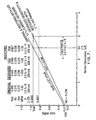
- the following example illustrates the parameter degradation occurring for both types of sensitivity change and shows one value for the reduced LED drive current for the High Sensitivity Test.
- the smoke detector of the following example utilizes a Motorola MC145010 ASIC as is explained further below.
- parameter mid-values substituted in eq. (4) for a smoke detector with factory-set alarm sensitivities of 2.5 %/ft results in the following.
- S 0 2.5 %/ft
- V b0 0.27 volts
- V sn0 0.27 volts/%/ft
- V cal 0.945 volts
- NFM 0 1 (%/ft) -1
- Test Strength is substituted in eq. (4) as a degraded sensitivity, S 1 , imposing the most logical constraint that the NFM remains constant at NFM 0 . That is, it is reasonable that attenuating grease films and the like on LED/PD optical elements will reduce both the background and the optical sensitivity by a factor, K 1 , less than 1. Rewriting eq.
- the microprocessor is utilized to invert the sense of the normal Low Sensitivity Test and annunciate Trouble when the increased background measured through the test channel reaches the alarm threshold, V cal .
- the reduced LED drive is in one embodiment set by fixed resistors. Also this Self-Diagnostic design still operates with a single potentiometer for factory setting of alarm sensitivity, S.
- V sn I LED * Q LED * 1/A s * n * R e * R L * A
- the average background will be some 0.286 volts.
- the alarm threshold, V cal is 1 volt.
- LED current is set at an average value of 0.177 amperes to establish a Vsn of 0.244 V/%/ft and a background of 0.244 volts.
- the fundamental adjustability of the LED drive current makes it one of the preferred means of manual or automatic adjustment in a Self Diagnostic design with a self-correction feature.
- Means for changing the LED current to accommodate a changed Background which has shifted the Alarm Point, S could utilize digitally activated switches which affect the current limiting resistor for the LED.
- a bank of resistors each shunted by a transistor in turn controlled by the microprocessor is one example.
- a network of a fixed resistor and two resistors having shunting saturable transistors would achieve a system of four possible resistance values, and consequently four LED current levels.
- a laser-trimmed fixed resistor to set the original Alarm Point at the factory may be utilized and the switchable resistors used to affect the needed background adjustment with the normal dust deposition in the installation or the rare condition of background decrease.
- EEPOT Digitally Controlled Potentiometer a device such as the X9CMME from Xicor with resolution of 1%, that is 100 selectable steps over the resistance range. Use of this type of device could provide the means for factory setting of sensitivity as well as the corrections needed in the field.
- a 21% Background Reduction will desensitize the Alarm Point by 38%.
- Such a fault condition is determined by the automatic Low Sensitivity Test.
- a 50% Background Increase increased the Sensitivity by 20%.
- This fault condition was determined by the High Sensitivity Test.
- different corrective actions may be warranted. For instance, where the Background (and Sensitivity) decreases are shown by the Low Sensitivity Test, but the High Sensitivity Test shows no fault condition, it may be desired to step up the LED drive current one step at a time until a Low Sensitivity Test shows the fault condition is eliminated.
- a microprocessor provides the functions of a long time base clock initiating High Sensitivity Test Commands which are buffered to three active switches connected to typical photoelectric smoke detector elements as would be used in conjunction with application specific integrated circuits (ASIC) such as the Motorola MC145010, namely: Test Command, LED Driver, Alarm Annunciator (Horn).
- ASIC application specific integrated circuits
- ASIC Motorola MC145010
- Test Command LED Driver
- Alarm Annunciator Horn
- a single input to the microprocessor is taken from the ASIC Horn Driver.
- Two other microprocessor outputs are the Sensitivity Decrease Command to the active switch to adjust the Bias of the Photodiode receiver circuit and an Annunciation Signal of the fact that automatic compensation of the Detector Smoke Sensitivity has been put into effect.
- a positive output drives S1 to activate the Test Command to the detector circuit.
- a negative output drives S2 to inhibit the "Trouble" Chirp at the horn from sounding and also drives S3 to lower the LED drive current.
- This approach essentially inverts the normal ASIC Test for Low Sensitivity.
- the alarm threshold will not be exceeded and the ASIC will provide a "chirp" pulse which will be processed at the input to the microprocessor as an indication that no compensation is required.
- This High Sensitivity Test approach may be incorporated with additional circuitry processing the built-in Low Sensitivity Test which occurs at a regular interval, every 43 seconds, or so, for the Motorola MC145010.
- the Trouble chirp in the absence of a High Sensitivity Test Command
- a microprocessor based controller contains a master clock and pulse counter to command IR LED pulses to an amplitude controllable driver to set in the smoke alarm sensitivity at time of manufacture and as needed for sensitivity adjustment during its life in the installed location as determined by Trouble Logic.
- the background scattered chamber reflections and any smoke signal added thereto as detected by the photodiode and amplified by the transresistance amplifier is fed to the gated peak detector and held during the interpulse period for processing by the Alarm and Trouble Threshold and Logic circuitry. Pulses exceeding V cal constitute a smoke alarm condition at the factory set sensitivity, S 0 .
Landscapes
- Engineering & Computer Science (AREA)
- Computer Security & Cryptography (AREA)
- Physics & Mathematics (AREA)
- General Physics & Mathematics (AREA)
- Fire-Detection Mechanisms (AREA)
- Investigating Or Analysing Materials By Optical Means (AREA)
- Fire Alarms (AREA)
Claims (14)
- Procédé permettant de détecter si un circuit d'alarme fonctionne en dehors de son domaine de sensibilité, le circuit d'alarme comportant un signal de fond et un signal de seuil d'alarme préfixé, le procédé consistant :de sorte que l'unité d'alarme fonctionne en dehors de son domaine de sensibilité lorsque le premier signal d'essai est inférieur au signal de seuil d'alarme ou le second signal d'essai est supérieur au signal de seuil d'alarme.a) à accroítre le signal de fond d'un premier facteur de gain de façon à produire un premier signal d'essai indiquant la sensibilité optique du détecteur de fumée,b) à accroítre le signal de fond d'un second facteur de gain inférieur au premier facteur de gain de façon à produire un second signal d'essai indiquant le signal de fond du détecteur de fumée,c) à comparer les premiers et seconds signaux d'essai au signal de seuil d'alarme,
- Procédé tel que revendiqué à la revendication 1, selon lequel le circuit d'alarme comprend un émetteur et un détecteur.
- Procédé permettant de maintenir un circuit d'alarme dans les limites de son domaine de sensibilité, le circuit d'alarme comprenant un émetteur et un détecteur et comportant un signal de fond et un signal de seuil d'alarme préfixé, le procédé consistant :a) à accroítre le signal de fond d'un premier facteur de gain de façon à produire un premier signal d'essai indiquant la sensibilité optique du détecteur de fumée,b) à accroítre le signal de fond d'un second facteur de gain inférieur au premier facteur de gain de façon à produire un second signal d'essai indiquant le signal de fond du détecteur de fumée,c) à comparer les premiers et seconds signaux d'essai au signal de seuil d'alarme,d) à ajuster la sortie d'émetteur et/ou le signal de seuil d'alarme, si nécessaire, de façon à maintenir le premier signal d'essai supérieur ou égal au signal de seuil d'alarme et le second signal d'essai inférieur ou égal au signal de seuil d'alarme.
- Procédé tel que revendiqué à la revendication 1, à la revendication 2 ou à la revendication 3, selon lequel le second facteur de gain est déduit d'une combinaison du premier facteur de gain et d'un ajustement de la sortie de l'émetteur.
- Procédé tel que revendiqué à une revendication précédente quelconque, selon lequel le circuit d'alarme est un détecteur de fumée optique comportant un émetteur de lumières et un détecteur de lumière.
- Procédé tel que revendiqué à la revendication 5, selon lequel le second signal d'essai est créé en réduisant la sortie de l'émetteur de lumière de façon à produire un signal de fond réduit qui est alors accru du premier facteur de gain.
- Procédé tel que revendiqué à la revendication 6, selon lequel la sortie de l'émetteur de lumière est réduite en réduisant le courant appliqué à l'émetteur de lumière.
- Détecteur de fumée dispersant la lumière, possédant un domaine de sensibilité spécifié et étant capable de déterminer si le détecteur fonctionne dans les limites de son domaine de sensibilité spécifié, le détecteur comprenant :un émetteur de lumière émettant un faisceau de lumière dans une chambre de fumée,un détecteur de lumière observant dans la chambre de fumée et capable de détecter le niveau de lumière dispersée sous l'effet de la présence de particules de fumée dans la chambre de fumée, la sortie du détecteur de lumière étant proportionnelle à la quantité de lumière dispersée rencontrant le détecteur,des moyens formant circuit d'alarme servant à annoncer une alarme lorsque la sortie du détecteur de lumière atteint ou dépasse un niveau de seuil d'alarme,des moyens formant circuit de commande comprenant des moyens servant à produire un premier signal d'essai en tant qu'indication de la sensibilité optique du détecteur de fumée, des moyens servant à produire un second signal d'essai en tant qu'indication du niveau de fond de la sortie du détecteur de lumière en l'absence de particules de fumée, et des moyens servant à déterminer à partir des signaux d'essai si le détecteur de fumée présente une condition de défaut et fonctionne en dehors de son domaine de sensibilité spécifié.
- Détecteur de fumée tel que revendiqué à la revendication 8, dans lequel les moyens servant à produire un premier signal d'essai en tant qu'indication de la sensibilité optique du détecteur de fumée comprennent des moyens servant à accroítre le signal de fond d'un premier facteur de gain.
- Détecteur de fumée tel que revendiqué à la revendication 9, dans lequel les moyens servant à produire un second signal d'essai en tant qu'indication du niveau de fond de la sortie du détecteur de lumière en l'absence de particules de fumée comprennent des moyens servant à accroítre le signal de fond d'un second facteur de gain.
- Détecteur de fumée tel que revendiqué à la revendication 10, dans lequel les moyens servant à accroítre le signal de fond du second facteur de gain comprennent des moyens servant à réduire la sortie de l'émetteur de lumière de façon à produire un signal de fond réduit qui est alors accru du premier facteur de gain.
- Détecteur de fumée tel que revendiqué à la revendication 11, dans lequel les moyens formant circuit de commande comprennent des moyens servant à ajuster le courant appliqué à l'émetteur de lumière et des moyens servant à ajuster le niveau de seuil d'alarme.
- Détecteur de fumée tel que revendiqué à la revendication 12, dans lequel la sortie de l'émetteur de lumière est réduite en réduisant le courant appliqué à l'émetteur de lumière.
- Détecteur de fumée tel que revendiqué à la revendication 13, dans lequel les moyens formant circuit de commande comprennent des moyens servant à ajuster le signal de seuil d'alarme et/ou le courant appliqué à l'émetteur de lumière de façon à ramener le détecteur de fumée à fonctionner dans les limites de son domaine de sensibilité lorsque la condition de défaut est déterminée.
Applications Claiming Priority (3)
| Application Number | Priority Date | Filing Date | Title |
|---|---|---|---|
| US08/422,512 US5523743A (en) | 1995-04-13 | 1995-04-13 | Self-diagnostic smoke detector |
| US422512 | 1995-04-13 | ||
| PCT/CA1996/000237 WO1996032705A1 (fr) | 1995-04-13 | 1996-04-15 | Detecteur de fumee a auto-diagnostic |
Publications (2)
| Publication Number | Publication Date |
|---|---|
| EP0765513A1 EP0765513A1 (fr) | 1997-04-02 |
| EP0765513B1 true EP0765513B1 (fr) | 2000-06-21 |
Family
ID=23675223
Family Applications (1)
| Application Number | Title | Priority Date | Filing Date |
|---|---|---|---|
| EP96908978A Expired - Lifetime EP0765513B1 (fr) | 1995-04-13 | 1996-04-15 | Detecteur de fumee a auto-diagnostic |
Country Status (6)
| Country | Link |
|---|---|
| US (1) | US5523743A (fr) |
| EP (1) | EP0765513B1 (fr) |
| AU (1) | AU5266396A (fr) |
| CA (1) | CA2174175C (fr) |
| DE (1) | DE69608934T2 (fr) |
| WO (1) | WO1996032705A1 (fr) |
Cited By (2)
| Publication number | Priority date | Publication date | Assignee | Title |
|---|---|---|---|---|
| DE102009054141A1 (de) | 2009-11-13 | 2011-05-19 | Job Lizenz Gmbh & Co Kg | Verfahren zum Prüfen der Funktion eines Rauchmelders |
| WO2019089450A1 (fr) | 2017-10-30 | 2019-05-09 | Carrier Corporation | Compensateur dans un dispositif détecteur |
Families Citing this family (27)
| Publication number | Priority date | Publication date | Assignee | Title |
|---|---|---|---|---|
| US6107925A (en) * | 1993-06-14 | 2000-08-22 | Edwards Systems Technology, Inc. | Method for dynamically adjusting criteria for detecting fire through smoke concentration |
| US5945924A (en) * | 1996-01-29 | 1999-08-31 | Marman; Douglas H. | Fire and smoke detection and control system |
| EP1098284B1 (fr) * | 1999-11-05 | 2004-05-06 | E.I. Technology Limited | Dispositif d'alarme de fumée |
| US6225910B1 (en) | 1999-12-08 | 2001-05-01 | Gentex Corporation | Smoke detector |
| US6876305B2 (en) | 1999-12-08 | 2005-04-05 | Gentex Corporation | Compact particle sensor |
| RU2218603C2 (ru) * | 2001-08-01 | 2003-12-10 | Овчинников Валерий Васильевич | Способ обработки сигнала в оптическом дымовом пожарном извещателе |
| DK1369836T3 (da) * | 2002-05-08 | 2006-05-01 | Hekatron Technik Gmbh | Brandalarm og fremgangsmåde til drift af en brandalarm |
| KR20040037493A (ko) * | 2002-10-28 | 2004-05-07 | 주식회사 포스코 | 센서의 자기 진단 장치 및 방법 |
| DE10300848B4 (de) * | 2003-01-10 | 2005-02-17 | Hekatron Vertriebs Gmbh | Brandschalter für Lüftungsanlagen |
| US7180594B2 (en) * | 2004-05-27 | 2007-02-20 | Finesse Instruments, Llc. | Method and apparatus for verifying proper operation of a photometric device, such as a cell density probe |
| US7224284B2 (en) * | 2004-07-09 | 2007-05-29 | Tyco Safety Products Canada Ltd. | Smoke detector calibration |
| US7579947B2 (en) * | 2005-10-19 | 2009-08-25 | Rosemount Inc. | Industrial process sensor with sensor coating detection |
| US7616126B2 (en) * | 2006-07-18 | 2009-11-10 | Gentex Corporation | Optical particle detectors |
| US7642924B2 (en) * | 2007-03-02 | 2010-01-05 | Walter Kidde Portable Equipment, Inc. | Alarm with CO and smoke sensors |
| US7895000B2 (en) * | 2007-09-04 | 2011-02-22 | Venturedyne, Ltd. | Environmental sensor, particle counting system having an environmental sensor, and methods of operating the same |
| US7724150B2 (en) * | 2007-09-04 | 2010-05-25 | Venturedyne, Ltd. | Environmental sensor, particle counting system having an environmental sensor, and methods of operating the same |
| CA2735715C (fr) * | 2008-09-05 | 2018-10-23 | Xtralis Technologies Ltd | Detection optique de caracteristiques de particules |
| US8988660B2 (en) * | 2011-06-29 | 2015-03-24 | Silicon Laboratories Inc. | Optical detector |
| US9396637B2 (en) | 2012-07-13 | 2016-07-19 | Walter Kidde Portable Equipment, Inc | Photoelectric smoke detector with drift compensation |
| DE102012217156A1 (de) * | 2012-09-24 | 2014-03-27 | Robert Bosch Gmbh | Auswerteeinrichtung für ein Überwachungssystem sowie Überwachungssystem mit der Auswerteeinrichtung |
| CN103674843B (zh) * | 2013-12-31 | 2016-02-10 | 上海贝岭股份有限公司 | 光电烟雾探测器及其使用方法 |
| US10002510B2 (en) * | 2015-12-09 | 2018-06-19 | Noah Lael Ryder | System and methods for detecting, confirming, classifying, and monitoring a fire |
| ES2823182T3 (es) | 2016-07-19 | 2021-05-06 | Autronica Fire & Security As | Sistema y método de verificación de la integridad operativa de un detector de humo |
| AU2018354716A1 (en) * | 2017-10-27 | 2020-06-11 | Diligent Fire & Safety Pty Ltd | Fire detection system, automatic data capture, remote testing, analysis, apparatus and methods |
| US11127284B1 (en) | 2020-07-02 | 2021-09-21 | Honeywell International Inc. | Self-calibrating fire sensing device |
| US12166233B2 (en) | 2021-06-18 | 2024-12-10 | Fire & Risk Alliance, LLC | System and method for fire detection and mitigation for energy storage systems |
| US12233825B2 (en) | 2022-07-25 | 2025-02-25 | Fire & Risk Alliance, LLC | Method for hazard detection and fire prevention in a mobile refueling system |
Family Cites Families (18)
| Publication number | Priority date | Publication date | Assignee | Title |
|---|---|---|---|---|
| US3868184A (en) * | 1973-07-25 | 1975-02-25 | Electro Signal Lab | Optical smoke detector with light scattering test device |
| US4206456A (en) * | 1975-06-23 | 1980-06-03 | Chloride Incorporated | Smoke detector |
| US4232307A (en) * | 1978-12-18 | 1980-11-04 | American District Telegraph Company | Electrical test circuit for optical particle detector |
| US4321466A (en) * | 1979-11-26 | 1982-03-23 | Isotec Industries Limited | Sensitivity test system for photoelectric smoke detector by changing light source intensity |
| JPS59187246A (ja) * | 1983-04-08 | 1984-10-24 | Nohmi Bosai Kogyo Co Ltd | 光電式煙感知器の機能検査装置 |
| EP0248957A1 (fr) * | 1986-06-12 | 1987-12-16 | Pittway Corporation | Détecteur auto-testant pour produits de combustion |
| US4595914A (en) * | 1983-04-11 | 1986-06-17 | Pittway Corporation | Self-testing combustion products detector |
| JPS60144458U (ja) * | 1984-03-05 | 1985-09-25 | ホーチキ株式会社 | 火災検出装置 |
| US4616928A (en) * | 1984-06-20 | 1986-10-14 | Kidde, Inc. | Photoelectric smoke detector with adjustable background signal |
| JPS61247918A (ja) * | 1985-04-26 | 1986-11-05 | Hochiki Corp | アナログセンサの出力補正装置 |
| US4827247A (en) * | 1985-05-08 | 1989-05-02 | Adt, Inc. | Self-compensating projected-beam smoke detector |
| US4749871A (en) * | 1985-05-08 | 1988-06-07 | Adt, Inc. | Self-diagnostic projected-beam smoke detector |
| US4687924A (en) * | 1985-05-08 | 1987-08-18 | Adt Inc. | Modular transceiver with adjustable specular member |
| US4728935A (en) * | 1986-04-11 | 1988-03-01 | Adt, Inc. | Integrity securing monitor and method for a security installation |
| US4965556A (en) * | 1988-03-08 | 1990-10-23 | Seatt Corporation | Combustion products detector having self-actuated periodic testing signal |
| US5170150A (en) * | 1991-01-25 | 1992-12-08 | Gentex Corporation | Photoelectric smoke detector with improved testing means |
| EP0503167B1 (fr) * | 1991-03-12 | 1995-06-14 | Matsushita Electric Works, Ltd. | Détecteur de fumée et procédé pour tester un tel détecteur |
| US5546074A (en) * | 1993-08-19 | 1996-08-13 | Sentrol, Inc. | Smoke detector system with self-diagnostic capabilities and replaceable smoke intake canopy |
-
1995
- 1995-04-13 US US08/422,512 patent/US5523743A/en not_active Expired - Lifetime
-
1996
- 1996-04-15 AU AU52663/96A patent/AU5266396A/en not_active Abandoned
- 1996-04-15 CA CA002174175A patent/CA2174175C/fr not_active Expired - Lifetime
- 1996-04-15 EP EP96908978A patent/EP0765513B1/fr not_active Expired - Lifetime
- 1996-04-15 DE DE69608934T patent/DE69608934T2/de not_active Expired - Lifetime
- 1996-04-15 WO PCT/CA1996/000237 patent/WO1996032705A1/fr not_active Ceased
Cited By (3)
| Publication number | Priority date | Publication date | Assignee | Title |
|---|---|---|---|---|
| DE102009054141A1 (de) | 2009-11-13 | 2011-05-19 | Job Lizenz Gmbh & Co Kg | Verfahren zum Prüfen der Funktion eines Rauchmelders |
| WO2019089450A1 (fr) | 2017-10-30 | 2019-05-09 | Carrier Corporation | Compensateur dans un dispositif détecteur |
| US11790751B2 (en) | 2017-10-30 | 2023-10-17 | Carrier Corporation | Compensator in a detector device |
Also Published As
| Publication number | Publication date |
|---|---|
| CA2174175A1 (fr) | 1996-10-14 |
| DE69608934T2 (de) | 2000-11-02 |
| US5523743A (en) | 1996-06-04 |
| DE69608934D1 (de) | 2000-07-27 |
| CA2174175C (fr) | 2000-07-25 |
| EP0765513A1 (fr) | 1997-04-02 |
| AU5266396A (en) | 1996-10-30 |
| WO1996032705A1 (fr) | 1996-10-17 |
Similar Documents
| Publication | Publication Date | Title |
|---|---|---|
| EP0765513B1 (fr) | Detecteur de fumee a auto-diagnostic | |
| EP0777895B1 (fr) | Detecteur de fumee autonome autoreglable et procede permettant de le faire fonctionner | |
| EP0581569B1 (fr) | Système de détection d'intrusion utilisant la technique d'un capteur adaptatif | |
| CN1032231C (zh) | 光电型火灾探测器 | |
| US5859706A (en) | Photoelectric smoke detector and disaster monitoring system using the photoelectric smoke detector | |
| US5093656A (en) | Active supervision of motion-detection systems | |
| US4636774A (en) | Variable sensitivity motion detector | |
| US4695734A (en) | Photoelectric smoke sensor including a photosensing data correction ratio correction circuit | |
| JPH0441395B2 (fr) | ||
| EP1098284B1 (fr) | Dispositif d'alarme de fumée | |
| JPH0244385B2 (fr) | ||
| US6362743B1 (en) | Smoke alarm with dual sensing technologies and dual power sources | |
| US5623249A (en) | Video monitor motion sensor | |
| AU666445B2 (en) | Fire detector | |
| US4064509A (en) | Intrusion detection systems employing automatic sensitivity adjustments | |
| US20030127585A1 (en) | Obscuration detector | |
| US4308531A (en) | Light transmission type smoke detector | |
| EP0113461B1 (fr) | Moyens fonctionnels de test pour un détecteur de fumée du type à dispersion de lumière | |
| AU750314B2 (en) | Light obstruction type smoke sensor | |
| JP3278300B2 (ja) | 画像形成装置 | |
| US6034601A (en) | Method and apparatus for determining proper installation of alarm devices | |
| GB2111193A (en) | Method and apparatus for assessing the quality of cement clinker | |
| JP3067851B2 (ja) | 反射型赤外線センサ及びそれを用いたセンサシステム | |
| JPH0563838B2 (fr) | ||
| JP3432258B2 (ja) | 超音波警報器 |
Legal Events
| Date | Code | Title | Description |
|---|---|---|---|
| PUAI | Public reference made under article 153(3) epc to a published international application that has entered the european phase |
Free format text: ORIGINAL CODE: 0009012 |
|
| 17P | Request for examination filed |
Effective date: 19961203 |
|
| AK | Designated contracting states |
Kind code of ref document: A1 Designated state(s): DE FR GB IT |
|
| GRAG | Despatch of communication of intention to grant |
Free format text: ORIGINAL CODE: EPIDOS AGRA |
|
| 17Q | First examination report despatched |
Effective date: 19990610 |
|
| GRAG | Despatch of communication of intention to grant |
Free format text: ORIGINAL CODE: EPIDOS AGRA |
|
| GRAH | Despatch of communication of intention to grant a patent |
Free format text: ORIGINAL CODE: EPIDOS IGRA |
|
| GRAH | Despatch of communication of intention to grant a patent |
Free format text: ORIGINAL CODE: EPIDOS IGRA |
|
| GRAA | (expected) grant |
Free format text: ORIGINAL CODE: 0009210 |
|
| ITF | It: translation for a ep patent filed | ||
| AK | Designated contracting states |
Kind code of ref document: B1 Designated state(s): DE FR GB IT |
|
| REF | Corresponds to: |
Ref document number: 69608934 Country of ref document: DE Date of ref document: 20000727 |
|
| ET | Fr: translation filed | ||
| PLBE | No opposition filed within time limit |
Free format text: ORIGINAL CODE: 0009261 |
|
| STAA | Information on the status of an ep patent application or granted ep patent |
Free format text: STATUS: NO OPPOSITION FILED WITHIN TIME LIMIT |
|
| 26N | No opposition filed | ||
| REG | Reference to a national code |
Ref country code: GB Ref legal event code: IF02 |
|
| REG | Reference to a national code |
Ref country code: FR Ref legal event code: CD |
|
| REG | Reference to a national code |
Ref country code: FR Ref legal event code: PLFP Year of fee payment: 20 |
|
| PGFP | Annual fee paid to national office [announced via postgrant information from national office to epo] |
Ref country code: GB Payment date: 20150427 Year of fee payment: 20 Ref country code: DE Payment date: 20150429 Year of fee payment: 20 |
|
| PGFP | Annual fee paid to national office [announced via postgrant information from national office to epo] |
Ref country code: IT Payment date: 20150427 Year of fee payment: 20 Ref country code: FR Payment date: 20150417 Year of fee payment: 20 |
|
| REG | Reference to a national code |
Ref country code: DE Ref legal event code: R071 Ref document number: 69608934 Country of ref document: DE |
|
| REG | Reference to a national code |
Ref country code: GB Ref legal event code: PE20 Expiry date: 20160414 |
|
| PG25 | Lapsed in a contracting state [announced via postgrant information from national office to epo] |
Ref country code: GB Free format text: LAPSE BECAUSE OF EXPIRATION OF PROTECTION Effective date: 20160414 |