EP0765586B1 - Verfahren und system zum sichern eines kommunikationsdienstes in einer deckungslosen zone - Google Patents
Verfahren und system zum sichern eines kommunikationsdienstes in einer deckungslosen zone Download PDFInfo
- Publication number
- EP0765586B1 EP0765586B1 EP96910458A EP96910458A EP0765586B1 EP 0765586 B1 EP0765586 B1 EP 0765586B1 EP 96910458 A EP96910458 A EP 96910458A EP 96910458 A EP96910458 A EP 96910458A EP 0765586 B1 EP0765586 B1 EP 0765586B1
- Authority
- EP
- European Patent Office
- Prior art keywords
- power
- transmitter
- base
- opposite
- base site
- Prior art date
- Legal status (The legal status is an assumption and is not a legal conclusion. Google has not performed a legal analysis and makes no representation as to the accuracy of the status listed.)
- Expired - Lifetime
Links
Images



Classifications
-
- H—ELECTRICITY
- H04—ELECTRIC COMMUNICATION TECHNIQUE
- H04W—WIRELESS COMMUNICATION NETWORKS
- H04W24/00—Supervisory, monitoring or testing arrangements
- H04W24/04—Arrangements for maintaining operational condition
Definitions
- the present application relates generally to the field of communication systems and more particularly to a method and system for providing communication service to a coverage hole.
- Cellular communication systems are generally designed to have redundant components to insure communication service is not lost when a component fails.
- This redundancy requires and an extra transceiver for every active transceiver, and extra power amplifier for every active amplifier, an extra controller for every active controller and all these extra (redundant) components greatly increase the cost of a cellular communication system.
- Under the present system when a transmitter or power amplifier fails the redundant transmitter is used until the failed transmitter can be fixed.
- the redundancy also increases the amount of maintenance and repair costs. Both the active and the redundant transmitter requires periodic calibration and maintenance. If the redundancy requirements could be reduced in a cellular communication system, it would significantly lower the cellular operator's cost of business.
- FIG. 1 shows a simulation of a DS-CDMA cellular communication system 10.
- the "X"s 12 are base sites with omni-directional transmitters.
- the "o"s 14 are active mobiles (portables, subscriber units).
- the simulator has randomly place the mobiles 14 in the cellular system 10.
- the lines 16 define the cell boundaries and are lines of constant energy per chip (E c ) divided by total interference energy (I o ) or (E c /I o ) that would be detected by a mobile at that spot.
- the cell boundaries 16 overlap 18 to form areas of soft handoff.
- FIG. 2 shows what happens if the transmitter for the center base station 20 fails. As can be seen from FIG. 2, a coverage gap 22 exists around the center base station 20. The coverage gap 22 exists even though the surrounding cells' boundaries 16 have expanded.
- the obvious solution to the coverage gap 22 left by the failed transmitter is to increase the power of the transmitters of the adjacent cells. This solution results in increasing the self interference from all the adjacent cell transmitters and does not close the coverage gap 12.
- GB-A-2 280 570 discloses a radio communications system in which base stations in adjacent cells increase the power transmitted from radio channel unit transceivers controlling sectors adjacent to that particular cell, thereby covering the gap in coverage left by the failure of that cell.
- EP-A-0 615 395 discloses a cellular mobile communication system that includes a plurality of base stations connected to a relay station, each base station having adaptability for coping with change in traffic volume within a relevant cell covered thereby.
- the relay station issues a command for lowering the power gain for the base station which covers a traffic-congested cell while raising the power gain for the base stations covering the neighbouring cells, to thereby reduce the size of the traffic-congested cell.
- the present invention provides a method of providing communication service to a coverage hole, as claimed in claim 1.
- the present invention provides a cellular communication system capable of providing service to a coverage hole created by a failure of a transmitter, as claimed in claim 5.
- the invention supplies a method and system to provide communication for a coverage gap in DS-CDMA cellular communication system. This eliminates the need for duplicate transmitters, reducing both acquisition costs and maintenance costs for a DS-CDMA cellular communication system.
- FIG. 3 shows a block diagram of a typical cellular communication system 50.
- An operations and maintenance center (OMC) 52 monitors and controls all aspects of the cellular communications system.
- the OMC 52 is connected to the other parts of the cellular communication system 50 through a switch and control (routing) system 54.
- the switching and control system 54 is also connected to the public switch telephone network (PSTN) 56 and a plurality of base site controllers (BSC) 58.
- PSTN public switch telephone network
- BSC base site controllers
- the BSCs 58 has a controller 60 and a plurality of transcoders (XCDR) 62.
- Each BSC 58 is coupled to a plurality of base site transceivers (BTS) 64.
- the BTS 64 is generally located in the center of a cell and corresponds to the "X"s 12 of FIG. 1.
- the BTSs 64 have a controller 68, a plurality of transceivers (transmitters and receivers) 70. a power amplifier (PA) 72 and an antenna 74.
- the OMC 52 is constantly monitoring the BTSs 64 and the BTSs 64 are constantly reporting a wide variety of information to the OMC 52, including if a transmitter 70 or power amplifier 72 have failed.
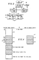
- the first strategy is called the constant power strategy 90.
- the second strategy is called the power on demand strategy 92.
- the figure shows total PA power out 94 as the vertical axis.
- a dashed line 96 shows the maximum power output of the PA.
- the constant power strategy 90 three components make up the total power used by the PA.
- the first group of power 98 is used by the pilot channel, paging channel and the synchronization channel.
- the second group 100 of power is used by the actual traffic channels in use.
- the third group 102 of power is used by dummy traffic channels. The idea behind powering the dummy traffic channels is to provide "constant" cell boundaries.
- FIG. 5 shows the effect of switching from the constant power mode shown in FIG. 2 to the power on demand mode. As can be seen by examining the two figures, the coverage hole 22 shrinks, but still exists.
- FIG. 6 shows an idealized cellular communication system with the familiar hexagonal cells and transmitters in the center of the cells.
- a cell 120 is shown without a transmitter to denote that the transmitter in cell 120 has failed.
- a plurality of adjacent cells 122-132, having coverage areas adjacent to the failed transmitter's coverage area have transmitters (base sites, BTSs) 134-144.
- Cells 122 and 128 are consider to be opposite cells (BTSs 134 & 140 are opposite BTSs). It follows that cells 124 and 130 are opposite cells and cells 132 and 126 are opposite cells.
- BTSs 134 & 140 are opposite BTSs
- the OMC determines the set of adjacent cells to the cell with the failed transmitter and places all the adjacent cell's transmitter in the power on demand mode, at block 202.
- the adjacent cells are then grouped in opposite pairs at block 204.
- a combined interference level for each of the opposite pairs is determined and the opposite pair with the lowest combined interference level is selected, at block 206.
- the interference level is determined from the received signal strength indicator (RSSI) at the base sites.
- the interference level can be selected to be the mean of the RSSI or the variance or some other statistical measure derived from the RSSI.
- the RSSI is an indicator of the level of interference in a DS-CDMA because a DS-CDMA cellular communication system is a self-interference system.
- the channels in DS-CDMA system share the same frequency spectrum.
- the power to the pilot channels of the selected opposite pair of transmitters is increased by 3 dB.
- the process described in FIG. 7, shifts the mobiles in the coverage hole to the two cells having the best reception and therefore the cells best able to accommodate more users.
- This process is able to provide communication service to the coverage hole because only a selected number of transmitters (cells) increase their pilot channel power.
- Increasing the pilot channel's power increases the cell's range.
- the pilot channel is the channel a mobile looks for from the base site to determine if the base site is available for communication.
- FIG. 8 is an alternative process for selecting a pair of opposite transmitters to fill the coverage gap.
- the process selects the adjacent transmitter with the largest amount of unused PA power. If the opposite transmitter has sufficient unused power to increase its pilot power 3 dB, this pair of transmitters is chosen to fill the coverage gap.
- the process starts at block 220.
- the process waits at block 222, until it is determined if a transmitter has failed.
- the OMC determines all the cells adjacent to the cell in which the transmitter has failed, at block 224.
- the OMC switches any of the adjacent cells in the constant power mode to the power on demand mode, at block 226.
- the OMC selects the adjacent cell (transmitter) with the most unused transmitter power, at block 228.
- the OMC determines if the cell opposite the selected cell has enough power to increase its pilot channel by 3 dB, at block 230. When the opposite cell does have sufficient power to raise its pilot channel by 3 dB, then the selected pair of transmitters increase the power to their pilot channels by 3 dB, at block 232. When the opposite cell does not have sufficient power to raise its pilot channel by 3 dB, then the OMC determines if all the adjacent cells have been selected at block 234. When not all the cells have been selected at block 234, the OMC selects the cell with the next largest unused transmit power at block 236. Processing then continues at block 230. When all the adjacent cells have been selected at block 234, the OMC chooses the pair of cells with the largest combination of unused power at block 238. This pair of selected transmitters then increases their power to their pilot channels, at block 240.
- a third alternative process is shown in FIG. 9 and incorporates parts of both the process of FIG. 8 and FIG. 7.
- the OMC determines the adjacent cells and places the transmitters in a power on demand mode at block 262.
- the adjacent transmitter with the largest quantity of unused transmitter power is selected at block 264.
- the OMC determines if the transmitter opposite the selected transmitter has sufficient power to increase its pilot channel 3 dB, at block 266.
- the OMC determines if both the selected and the opposite transmitter has interference levels below a predetermined threshold, at block 268.
- both the selected and the opposite transmitter has interference levels below a predetermined threshold, then the selected and opposite transmitters increase their pilot channel power by 3 dB, at block 270.
- the OMC selects the transmitter with the next largest unused transmitter power, at block 272. Processing would then return to block 266.
- the OMC determines if all the adjacent transmitters have been selected at block 274. When all the adjacent transmitters have not been selected at block 274, then processing continues at block 272. When all the adjacent transmitters have been selected at block 274. the OMC chooses the pair of opposite transmitters with the largest combination of unused power at block 278. Processing then continues at block 270.
- FIG. 10 is simulation of the process of FIG. 9. As can be seen from the figure, the coverage hole 22 that was evident in FIGs. 2 and 5 has been covered.
- the invention supplies a method and system for providing communication to a coverage hole in a DS-CDMA cellular communication system.
- the invention allows a cellular operator is reduce both its initial capital investment and the on going maintenance cost by eliminating the need for duplicate transmitters and power amplifiers. While the invention has been described in conjunction with specific embodiments thereof, it is evident that many alternatives, modifications, and variations will be apparent to those skilled in the art in light of the foregoing description. For instance, the invention has been described using omni directional transmitters, but could be easily modified to work with sectorized transmitters.
Landscapes
- Engineering & Computer Science (AREA)
- Computer Networks & Wireless Communication (AREA)
- Signal Processing (AREA)
- Mobile Radio Communication Systems (AREA)
Claims (5)
- Verfahren, um einem Abdeckungsloch einen Kommunikationsdienst zur Verfügung zu stellen, das die folgenden Schritte aufweist:(a) Bestimmen (224, 262) einer Vielzahl von Basisanlagen, die Abdeckungsgebiete haben, die neben dem Abdeckungsloch liegen;(b) Setzen (226, 262) eines Leistungsverstärkers, der der Vielzahl von Basisanlagen, die neben dem Abdeckungsloch liegen, zugeordnet ist, in einen Power-On-Demand-Modus;(c) Auswählen (228, 264) einer ausgewählten Basisanlage aus einer der Vielzahl der Basisanlagen, die Abdeckungsgebiete haben, die neben dem Abdeckungsloch liegen, basierend auf einer Quantität von unbenutzter Senderleistung in der ausgewählten Basisanlage;(d) Bestimmen (230, 266), ob eine gegenüberliegende Basisanlage eine hinreichende Quantität von unbenutzter Senderleistung hat; und(e) Erhöhen (232, 270) einer Pilot-Kanalleistung zu der ausgewählten Basisanlage und der gegenüberliegenden Basisanlage, wenn die gegenüberliegende Basisanlage die hinreichende Quantität von unbenutzter Senderleistung hat.
- Verfahren nach Anspruch 1, weiterhin die folgenden Schritte umfassend:(f) Auswählen (234, 236, 238, 272, 274, 276) einer alternativen Basisanlage unter der Vielzahl von Basisanlagen, die Abdeckungsgebiete haben, die neben dem Abdeckungsloch liegen, als die ausgewählte Basisanlage, basierend auf der Quantität von unbenutzter Senderleistung in der alternativen Basisanlage, wenn die gegenüberliegende Basisanlage keine hinreichende Quantität von unbenutzter Senderleistung hat; und(g) Wiederholen von Schritt (d).
- Verfahren nach Anspruch 1, wobei Schritt (e) weiterhin den Schritt umfasst, die Pilot-Kanalleistung zu der ausgewählten Basisanlage und der gegenüberliegenden Basisanlage zu erhöhen, wenn die gegenüberliegende Basisanlage die hinreichende Quantität von unbenutzter Senderleistung hat und ein Interferenzniveau von sowohl der ausgewählten als auch der gegenüberliegenden Basisanlage unter einem Schwellenwert liegt.
- Verfahren nach Anspruch 3, weiterhin die folgenden Schritte umfassend:(f) Auswählen (272) einer alternativen Basisanlage unter der Vielzahl von Basisanlagen, die Abdeckungsgebiete haben, die neben dem Abdeckungsloch liegen, als die ausgewählte Basisanlage, basierend auf einer Quantität von unbenutzter Senderleistung in der alternativen Basisanlage, wenn das Interferenzniveau von der ausgewählten oder der gegenüberliegenden Basisanlage über dem Schwellenwert liegt; und(g) Wiederholen von Schritt (d).
- Zellulares Kommunikationssystem (50), das dazu im Stande ist, einem Abdeckungsloch (120) einen Dienst zur Verfügung zu stellen, das durch einen Ausfall eines Senders entstanden ist, wobei das System aufweist:eine Vielzahl von Spreiz-Spektrum-Sendern (70, 134-144), der eine Vielzahl von benachbarten Basisanlagen (122-132) zugeordnet ist, die Abdeckungsgebiete haben, die neben dem Abdeckungsloch liegen; undein OMC (OMC = Operations and Management Center/Betriebs- und Managementzentrum) (52), das mit einer Vielzahl von Basisanlagen (64, 120-132) in Kommunikation steht und die Vielzahl von Basisanlagen auf einen Ausfall von irgendeinem der Vielzahl von Spreiz-Spektrum-Sendern überwacht, wobei das OMC aufweist:Mittel zum Senden (202) eines Signals zum Umschalten der Vielzahl von benachbarten Basisanlagen (122-132) in einem Konstantleistungsmodus zu einem Power-On-Demand-Modus;Mittel zum Gruppieren (204) der benachbarten Basisanlagen in gegenüberliegende Senderpaare, die Basisanlagen an gegenüberliegenden Seiten des ausgefallenen Senders sind;Mittel zum Bestimmen eines kombinierten Interferenzniveaus für jedes gegenüberliegende Senderpaar;Mittel zum Auswählen (206) eines Senderpaars mit dem niedrigsten kombinierten Interferenzniveau; undMittel zum Senden eines Signals, um Leistung zu einem Pilot-Kanal der ausgewählten Sender zu erhöhen (208), wobei den Sendern, deren Leistung erhöht wird, weniger als all die Basisanlagen zugeordnet sind, die neben dem ausgefallenen Spreiz-Spektrum-Sender liegen.
Applications Claiming Priority (4)
| Application Number | Priority Date | Filing Date | Title |
|---|---|---|---|
| US42101295A | 1995-04-12 | 1995-04-12 | |
| US421012 | 1995-04-12 | ||
| PCT/US1996/003575 WO1996032825A1 (en) | 1995-04-12 | 1996-03-15 | Method and system for providing communications service to a coverage hole |
| CA002192286A CA2192286C (en) | 1995-04-12 | 1996-12-06 | Method and system for providing communications service to a coverage hole |
Publications (3)
| Publication Number | Publication Date |
|---|---|
| EP0765586A1 EP0765586A1 (de) | 1997-04-02 |
| EP0765586A4 EP0765586A4 (de) | 1998-09-09 |
| EP0765586B1 true EP0765586B1 (de) | 2006-09-13 |
Family
ID=25678899
Family Applications (1)
| Application Number | Title | Priority Date | Filing Date |
|---|---|---|---|
| EP96910458A Expired - Lifetime EP0765586B1 (de) | 1995-04-12 | 1996-03-15 | Verfahren und system zum sichern eines kommunikationsdienstes in einer deckungslosen zone |
Country Status (9)
| Country | Link |
|---|---|
| US (1) | US5852778A (de) |
| EP (1) | EP0765586B1 (de) |
| JP (1) | JP3492699B2 (de) |
| AU (1) | AU5364696A (de) |
| CA (1) | CA2192286C (de) |
| FI (1) | FI964799A7 (de) |
| FR (1) | FR2733105B1 (de) |
| IL (1) | IL117557A0 (de) |
| WO (1) | WO1996032825A1 (de) |
Families Citing this family (30)
| Publication number | Priority date | Publication date | Assignee | Title |
|---|---|---|---|---|
| JPH10126282A (ja) * | 1996-10-16 | 1998-05-15 | Nec Corp | バースト信号送信装置 |
| US6119005A (en) * | 1998-05-27 | 2000-09-12 | Lucent Technologies Inc. | System for automated determination of handoff neighbor list for cellular communication systems |
| US5991618A (en) * | 1998-05-29 | 1999-11-23 | Motorola, Inc. | Method and system for estimating a communication mode quality in a wireless communications system |
| PT1101294E (pt) * | 1998-07-28 | 2011-03-15 | Samsung Electronics Co Ltd | Transmissão descontínua num estado de manutenção do canal de controlo num sistema de comunicações cdma |
| US6285664B1 (en) * | 1998-09-08 | 2001-09-04 | Lucent Technologies, Inc. | Method and apparatus for estimating pilot coverages |
| US6253087B1 (en) * | 1998-09-30 | 2001-06-26 | Telefonaktiebolaget Lm Ericsson | Method and system for improved traffic management in wireless telecommunication systems |
| US6119010A (en) * | 1998-10-13 | 2000-09-12 | Motorola, Inc. | Method and apparatus for adjusting channel powers in a wireless communication system based on a predicted mobile location |
| KR100670075B1 (ko) * | 1999-09-08 | 2007-01-18 | 유티스타콤코리아 유한회사 | 셀룰러 이동통신 시스템의 국간 회선 감시에 의한 호접속 관리방법 |
| AU728879B3 (en) * | 1999-12-29 | 2001-01-18 | Nortel Networks Corporation | System and methods for implementing large CDMA cell sizes |
| AU2001239934A1 (en) | 2000-04-27 | 2001-11-12 | Lgc Wireless, Inc. | Adaptive capacity management in a centralized basestation architecture |
| US7280495B1 (en) | 2000-08-18 | 2007-10-09 | Nortel Networks Limited | Reliable broadcast protocol in a wireless local area network |
| US7339892B1 (en) | 2000-08-18 | 2008-03-04 | Nortel Networks Limited | System and method for dynamic control of data packet fragmentation threshold in a wireless network |
| US7308279B1 (en) * | 2000-08-18 | 2007-12-11 | Nortel Networks Limited | Dynamic power level control on transmitted messages in a wireless LAN |
| US7366103B2 (en) * | 2000-08-18 | 2008-04-29 | Nortel Networks Limited | Seamless roaming options in an IEEE 802.11 compliant network |
| KR20020040071A (ko) * | 2000-11-23 | 2002-05-30 | 박종섭 | 셀 커버에이지를 이용한 통화 채널 분산 방법 |
| EP1274188B1 (de) * | 2001-07-06 | 2006-10-18 | Marconi Communications GmbH | Verfahren zur Überwachung eines redundanten Senders |
| US20090069008A1 (en) * | 2003-12-08 | 2009-03-12 | Highsmith William R | Situational bandwidth allocation in spectral reuse transceiver |
| US20060084441A1 (en) * | 2004-10-18 | 2006-04-20 | Interdigital Technology Corporation | Wireless communication method and system for restoring services previously provided by a disabled cell |
| US7480264B1 (en) * | 2005-02-10 | 2009-01-20 | Sonicwall, Inc. | Centralized wireless LAN load balancing |
| US7583962B2 (en) * | 2006-03-23 | 2009-09-01 | Samsung Electronics Co., Ltd. | Adjacent-cell assisted redundancy for wireless communication networks |
| US7826820B2 (en) * | 2006-09-08 | 2010-11-02 | Telefonaktiebolaget Lm Ericsson (Publ) | Non-homogenous telecommunications base stations |
| JP4899111B2 (ja) * | 2006-10-23 | 2012-03-21 | 富士通株式会社 | 移動通信システム |
| EP2220884B1 (de) * | 2007-12-17 | 2019-08-14 | Telefonaktiebolaget LM Ericsson (publ) | Verfahren und vorrichtung zur minderung von zellenausfall |
| EP2537359B1 (de) | 2010-02-18 | 2018-03-07 | Telefonaktiebolaget LM Ericsson (publ) | Ausgleich von abdeckungslöchern in einem zellfunksystem |
| GB2481614B (en) * | 2010-06-30 | 2017-11-22 | Fujitsu Ltd | Coverage hole compensation in wireless communication networks |
| US8521172B2 (en) | 2011-01-11 | 2013-08-27 | Scott R. Rosenau | Method and system for switching cellular base station capacity |
| GB2487222B (en) * | 2011-01-14 | 2015-02-25 | Fujitsu Ltd | Coverage hole compensation in a cellular wireless network |
| CN103548370B (zh) * | 2011-05-19 | 2017-08-11 | 日本电气株式会社 | 频谱控制系统、频谱控制方法、无线通信系统 |
| WO2013094092A1 (ja) * | 2011-12-22 | 2013-06-27 | 日本電気株式会社 | 基地局、通信システム、及び基地局の制御方法 |
| US20140355476A1 (en) * | 2013-06-03 | 2014-12-04 | Glen J. Anderson | Systems and methods for mesh network deployment |
Family Cites Families (8)
| Publication number | Priority date | Publication date | Assignee | Title |
|---|---|---|---|---|
| US4435840A (en) * | 1981-06-22 | 1984-03-06 | Nippon Electric Co., Ltd. | Radio mobile communication system wherein probability of loss of calls is reduced without a surplus of base station equipment |
| US5023900A (en) * | 1989-12-07 | 1991-06-11 | Tayloe Daniel R | Cellular radiotelephone diagnostic system |
| FI91344C (fi) * | 1991-03-05 | 1994-06-10 | Nokia Telecommunications Oy | Solukkoradioverkko, tukiasema sekä menetelmä liikennekapasiteetin säätämiseksi alueellisesti solukkoradioverkossa |
| JP2814838B2 (ja) * | 1992-06-09 | 1998-10-27 | 日本電気株式会社 | 基地局カバレッジ制御方式 |
| JPH06268574A (ja) * | 1993-03-11 | 1994-09-22 | Hitachi Ltd | セルラ移動通信システム |
| GB2280570B (en) * | 1993-07-31 | 1998-04-01 | Motorola Ltd | A communications system |
| US5513379A (en) * | 1994-05-04 | 1996-04-30 | At&T Corp. | Apparatus and method for dynamic resource allocation in wireless communication networks utilizing ordered borrowing |
| US5475870A (en) * | 1994-09-12 | 1995-12-12 | Qualcomm Incorporated | Apparatus and method for adding and removing a base station from a cellular communications system |
-
1996
- 1996-03-15 EP EP96910458A patent/EP0765586B1/de not_active Expired - Lifetime
- 1996-03-15 JP JP53100896A patent/JP3492699B2/ja not_active Expired - Fee Related
- 1996-03-15 WO PCT/US1996/003575 patent/WO1996032825A1/en not_active Ceased
- 1996-03-15 FI FI964799A patent/FI964799A7/fi unknown
- 1996-03-15 AU AU53646/96A patent/AU5364696A/en not_active Abandoned
- 1996-03-19 IL IL11755796A patent/IL117557A0/xx unknown
- 1996-04-04 FR FR9604230A patent/FR2733105B1/fr not_active Expired - Fee Related
- 1996-12-06 CA CA002192286A patent/CA2192286C/en not_active Expired - Fee Related
-
1997
- 1997-02-07 US US08/797,012 patent/US5852778A/en not_active Expired - Fee Related
Also Published As
| Publication number | Publication date |
|---|---|
| JPH10501952A (ja) | 1998-02-17 |
| JP3492699B2 (ja) | 2004-02-03 |
| US5852778A (en) | 1998-12-22 |
| EP0765586A1 (de) | 1997-04-02 |
| CA2192286A1 (en) | 1998-06-06 |
| FR2733105B1 (fr) | 1999-05-28 |
| FI964799A0 (fi) | 1996-11-29 |
| FR2733105A1 (fr) | 1996-10-18 |
| FI964799L (fi) | 1996-11-29 |
| WO1996032825A1 (en) | 1996-10-17 |
| FI964799A7 (fi) | 1996-11-29 |
| CA2192286C (en) | 2000-05-02 |
| IL117557A0 (en) | 1996-07-23 |
| AU5364696A (en) | 1996-10-30 |
| EP0765586A4 (de) | 1998-09-09 |
Similar Documents
| Publication | Publication Date | Title |
|---|---|---|
| EP0765586B1 (de) | Verfahren und system zum sichern eines kommunikationsdienstes in einer deckungslosen zone | |
| EP1169785B1 (de) | Adaptive leistungssteuerung in einem mobilen funkkommunikationssystem | |
| US6763237B1 (en) | Method and apparatus for the selection of radio transmission resources | |
| CA2348990C (en) | Use of mobile locating and power control for radio network optimization | |
| AU673576B2 (en) | Access burst power control | |
| JP3019061B2 (ja) | 移動通信システム及びその無線回線制御方法 | |
| CN1092012C (zh) | 产生导频信号以执行硬切换的设备和方法 | |
| US6173188B1 (en) | Method of a forward power control using an erasure indicator bit | |
| EP0717914A1 (de) | Weiterreichverfahren und zellulares kommunikationssystem | |
| CA2412918A1 (en) | Cellular communications network having airborne transceivers | |
| WO1998057516A2 (en) | Control of transceiver units in cellular radio system | |
| EP1069702B1 (de) | Synchronisierung der Sendeleistungspegeleinstellungen während weichem Weiterreichen in einem drahtlosen System mittels Leistungspegelbegrenzungen | |
| EP0880239B1 (de) | Sendeleistungsregelungssystem, das fähig ist, die Kommunikation eines abnormal betriebenen Endgeräts auszuschalten | |
| KR101194135B1 (ko) | 매크로-다이버시티로 전송되는 기지국의 전송 전력을 조정하는 방법 | |
| US20030013448A1 (en) | Method for controlling a connecting relay in a radio communications system | |
| EP1576742B1 (de) | Verfahren und vorrichtung zur bestimmung einer sendeleistung | |
| US20040176126A1 (en) | Mobile communications system, radio controller, base station, and method of controlling transmission power | |
| EP1453222B1 (de) | Mobiles Kommunikationssystem, Funksteuereinrichtung, Basisstation und Verfahren zur Sendeleistungsregelung | |
| EP1254575B1 (de) | Fehlerbehandlung in einer basistation eines cdma systems | |
| CA2241363A1 (en) | A method for accessing a microcell using analog control channels | |
| EP1181783A1 (de) | Verfahren zur leistungssteuerung | |
| KR19990075970A (ko) | 이동통신 시스템에서의 파일롯 신호 제어방법 | |
| CN1084131C (zh) | 为覆盖孔提供通信服务的方法和系统 | |
| GB2356531A (en) | Load shedding in a CDMA network | |
| JP2003047040A (ja) | セルラー移動通信システム、及びその無線ゾーン制御方法 |
Legal Events
| Date | Code | Title | Description |
|---|---|---|---|
| PUAI | Public reference made under article 153(3) epc to a published international application that has entered the european phase |
Free format text: ORIGINAL CODE: 0009012 |
|
| AK | Designated contracting states |
Kind code of ref document: A1 Designated state(s): DE GB SE |
|
| 17P | Request for examination filed |
Effective date: 19970417 |
|
| RHK1 | Main classification (correction) |
Ipc: H04Q 7/34 |
|
| A4 | Supplementary search report drawn up and despatched | ||
| AK | Designated contracting states |
Kind code of ref document: A4 Designated state(s): DE GB SE |
|
| 17Q | First examination report despatched |
Effective date: 20030918 |
|
| GRAP | Despatch of communication of intention to grant a patent |
Free format text: ORIGINAL CODE: EPIDOSNIGR1 |
|
| GRAS | Grant fee paid |
Free format text: ORIGINAL CODE: EPIDOSNIGR3 |
|
| GRAA | (expected) grant |
Free format text: ORIGINAL CODE: 0009210 |
|
| AK | Designated contracting states |
Kind code of ref document: B1 Designated state(s): DE GB SE |
|
| REG | Reference to a national code |
Ref country code: GB Ref legal event code: FG4D |
|
| REF | Corresponds to: |
Ref document number: 69636535 Country of ref document: DE Date of ref document: 20061026 Kind code of ref document: P |
|
| PG25 | Lapsed in a contracting state [announced via postgrant information from national office to epo] |
Ref country code: SE Free format text: LAPSE BECAUSE OF FAILURE TO SUBMIT A TRANSLATION OF THE DESCRIPTION OR TO PAY THE FEE WITHIN THE PRESCRIBED TIME-LIMIT Effective date: 20061213 |
|
| PLBE | No opposition filed within time limit |
Free format text: ORIGINAL CODE: 0009261 |
|
| STAA | Information on the status of an ep patent application or granted ep patent |
Free format text: STATUS: NO OPPOSITION FILED WITHIN TIME LIMIT |
|
| 26N | No opposition filed |
Effective date: 20070614 |
|
| REG | Reference to a national code |
Ref country code: GB Ref legal event code: 732E Free format text: REGISTERED BETWEEN 20110127 AND 20110202 |
|
| REG | Reference to a national code |
Ref country code: DE Ref legal event code: R081 Ref document number: 69636535 Country of ref document: DE Owner name: MOTOROLA MOBILITY, INC. ( N.D. GES. D. STAATES, US Free format text: FORMER OWNER: MOTOROLA, INC., SCHAUMBURG, ILL., US Effective date: 20110324 Ref country code: DE Ref legal event code: R081 Ref document number: 69636535 Country of ref document: DE Owner name: MOTOROLA MOBILITY, INC. ( N.D. GES. D. STAATES, US Free format text: FORMER OWNER: MOTOROLA, INC., SCHAUMBURG, US Effective date: 20110324 |
|
| PGFP | Annual fee paid to national office [announced via postgrant information from national office to epo] |
Ref country code: DE Payment date: 20150327 Year of fee payment: 20 |
|
| PGFP | Annual fee paid to national office [announced via postgrant information from national office to epo] |
Ref country code: GB Payment date: 20150327 Year of fee payment: 20 |
|
| REG | Reference to a national code |
Ref country code: DE Ref legal event code: R071 Ref document number: 69636535 Country of ref document: DE |
|
| REG | Reference to a national code |
Ref country code: GB Ref legal event code: PE20 Expiry date: 20160314 |
|
| PG25 | Lapsed in a contracting state [announced via postgrant information from national office to epo] |
Ref country code: GB Free format text: LAPSE BECAUSE OF EXPIRATION OF PROTECTION Effective date: 20160314 |
|
| P01 | Opt-out of the competence of the unified patent court (upc) registered |
Effective date: 20230520 |