EP0765598B1 - Trennvorrichtung an Geräten zur Entnahme von Silage aus Flachsilos - Google Patents
Trennvorrichtung an Geräten zur Entnahme von Silage aus Flachsilos Download PDFInfo
- Publication number
- EP0765598B1 EP0765598B1 EP96112709A EP96112709A EP0765598B1 EP 0765598 B1 EP0765598 B1 EP 0765598B1 EP 96112709 A EP96112709 A EP 96112709A EP 96112709 A EP96112709 A EP 96112709A EP 0765598 B1 EP0765598 B1 EP 0765598B1
- Authority
- EP
- European Patent Office
- Prior art keywords
- separating device
- vibrator
- weight
- eccentric
- discs
- Prior art date
- Legal status (The legal status is an assumption and is not a legal conclusion. Google has not performed a legal analysis and makes no representation as to the accuracy of the status listed.)
- Expired - Lifetime
Links
- 239000004460 silage Substances 0.000 title claims description 7
- 229920001971 elastomer Polymers 0.000 claims abstract description 7
- 229910052751 metal Inorganic materials 0.000 claims abstract description 4
- 239000002184 metal Substances 0.000 claims abstract description 3
- 230000010355 oscillation Effects 0.000 claims abstract 2
- 239000011435 rock Substances 0.000 claims abstract 2
- 239000000872 buffer Substances 0.000 claims description 2
- RRHGJUQNOFWUDK-UHFFFAOYSA-N Isoprene Chemical compound CC(=C)C=C RRHGJUQNOFWUDK-UHFFFAOYSA-N 0.000 claims 1
- 229920001195 polyisoprene Polymers 0.000 claims 1
- 238000000926 separation method Methods 0.000 description 6
- 238000000855 fermentation Methods 0.000 description 3
- 238000012423 maintenance Methods 0.000 description 3
- 238000004519 manufacturing process Methods 0.000 description 3
- 238000013016 damping Methods 0.000 description 2
- 230000005284 excitation Effects 0.000 description 2
- 239000004459 forage Substances 0.000 description 2
- BMLMXLRJGCBOOF-UHFFFAOYSA-N CC(CC1)CC1=C Chemical compound CC(CC1)CC1=C BMLMXLRJGCBOOF-UHFFFAOYSA-N 0.000 description 1
- 229910000831 Steel Inorganic materials 0.000 description 1
- 230000000052 comparative effect Effects 0.000 description 1
- 238000010276 construction Methods 0.000 description 1
- 238000011982 device technology Methods 0.000 description 1
- 239000000463 material Substances 0.000 description 1
- 230000008439 repair process Effects 0.000 description 1
- 239000010959 steel Substances 0.000 description 1
Images


Classifications
-
- A—HUMAN NECESSITIES
- A01—AGRICULTURE; FORESTRY; ANIMAL HUSBANDRY; HUNTING; TRAPPING; FISHING
- A01F—PROCESSING OF HARVESTED PRODUCE; HAY OR STRAW PRESSES; DEVICES FOR STORING AGRICULTURAL OR HORTICULTURAL PRODUCE
- A01F25/00—Storing agricultural or horticultural produce; Hanging-up harvested fruit
- A01F25/16—Arrangements in forage silos
- A01F25/20—Unloading arrangements
- A01F25/2027—Unloading arrangements for trench silos
- A01F25/2036—Cutting or handling arrangements for silage blocks
-
- Y—GENERAL TAGGING OF NEW TECHNOLOGICAL DEVELOPMENTS; GENERAL TAGGING OF CROSS-SECTIONAL TECHNOLOGIES SPANNING OVER SEVERAL SECTIONS OF THE IPC; TECHNICAL SUBJECTS COVERED BY FORMER USPC CROSS-REFERENCE ART COLLECTIONS [XRACs] AND DIGESTS
- Y10—TECHNICAL SUBJECTS COVERED BY FORMER USPC
- Y10S—TECHNICAL SUBJECTS COVERED BY FORMER USPC CROSS-REFERENCE ART COLLECTIONS [XRACs] AND DIGESTS
- Y10S241/00—Solid material comminution or disintegration
- Y10S241/605—Hay unbaler
Definitions
- the present invention relates to a separation device for devices for removal from silage made of flat silos, the underside of which is straight, L-shaped or U-shaped Has course and which is provided with cutting on this underside and overall Movable up and down on rockers or vertical guides is.
- Separating devices of the generic type are on self-propelled, on drawn or devices attached to tractors for taking feed and distributing feed and feed mixing in various embodiments are known. she are used to separate silage feed and also partially to insert the separated one Feed into the holds of the corresponding devices or vehicles.
- a simple version is known as a silo comb, here are on the underside of the separator, across the entire width of the plate, comb-shaped tines are attached, with which the forage is scraped off the flat silo and into the associated cargo space is pushed.
- Such separators work dirty, on the flat silo itself a roughened surface is created and that Pushing the forage into the cargo area is dirty in the lower area of the tines. Post-fermentation and feed losses are considerable.
- the present invention has for its object a separation device Generic type to create that creates a clean cut on the flat silo and is characterized by a simple structure, so that the cost of Manufacturing and maintenance are low overall.
- the separating device over at least one vibrator can be driven oscillating or oscillating exclusively by its unbalance.
- Such a separating device is comparative due to the device technology easy to manufacture drive in the form of a vibrator, inexpensive to manufacture, Comparatively, it rarely needs maintenance and also provides for one clean, low-fermentation cut in the flat silo.
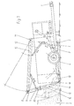
- the device for removal and distribution shown by way of example in FIGS. 1-3 of silage feed is preferably behind an agricultural, not shown Tractor attached to its farm rail 1.
- the device is moved backwards to a flat silo 2, whereby it by pivoting wheels 4 mounted on the axle rockers 3 by one Rotation axis 5 brought into the lowered working position by means of the hydraulic cylinders 6 becomes.
- a separation device 15 is via pick-up points 8 via a hydraulic cylinder 9 arranged pivotably on a rocker 10 of the device.
- the separator consists essentially of a cutting frame 16, a shield plate 17, one lower cutting edge 18, side cutting 19 and a flanged, shown in Embodiment hydraulically driven vibrator 20.
- the smooth or profiled cutting edges of the transverse cutting edge 18 and the side cutting edges 19 can be attached to the separating device 15 directly or via screwable strips.
- damping elements such as rubber springs, rubber buffers or bushings etc., preferably attached as rubber metal elements.
- the vibrator 20 is designed so that by opposing excitation of the mass forces the direction of vibration can be determined, it is expedient to the cutting edge 18 aligned.
- the number of vibrators can, if necessary increase.
- the drive is preferably hydraulic, but can also be electrical or by compressed air.
- the excitation of the vibrations can of course also be done by several vibrators, that rotate in the same direction or in opposite directions.
- the arrangement of the Vibrators can be linearly or angularly offset.
- vibration-damping elements preferably made of rubber-metal, can if necessary, can also be replaced by steel springs or pressure accumulators.
- the separating device 15 shown in FIGS. 4-7 is equipped with a vibrator 20a, which from a drive disk 22 which can be driven by a motor 21 and several unbalance disks 23.
- the unbalance disks 23 are over a Drive belt 24 through the drive wheel 22 driven by the motor 21 in rotation transferred.
- FIGS. 4-7 there are a total of four unbalance disks 23 provided, the total on a parallel to the cross disk 18 Level are arranged. Two of these unbalance disks 23 form one in the same direction driven pair, whereby the reversal of the direction of rotation of the two pairs is achieved is by a pulley 25, over which the belt 24 is guided.
- the unbalance disks 23 are each provided with weights 26 in order to achieve the desired one Generate unbalance. These weights 26 are in the embodiment of the invention according to Figures 4-7 arranged so that these on the outer unbalance disks 23 are arranged parallel to one another, and the weights 26 are likewise of the two inner unbalance disks 23 arranged in the same direction, but offset by 90 ° relative to the weights 26 of the outer unbalance disks 23. By arranging the weights 26 on the unbalance disks 23 can largely The frequency of those driven by the vibrator 20a are influenced Separator.
- the entire vibrator 20a is mounted on the shield plate 17, which has vibrating elements 27 is attached to the shield frame 16.
- the bearing of the unbalance disks 23 and the drive pulley 22 and the drive motor 21 via pins 30, the on the one hand are attached to the shield plate 17 and on the other hand an additional plate 28 wear, through which the entire vibrator 20a is covered at the same time. This is possible for example from Figure 5 very clearly.
- a gap cover 31 made of rubber or a similar material connects the Shield plate 17 with the shield frame 16 and prevents the ingress of dirt in the area of the vibrator 20a.
- the axes of the unbalance disks run 23 and the axis of the drive wheel 22 perpendicular to the shield plate 17, so that overall, there is a space-saving construction of the vibrator 20a on the shield plate 17 results.
- the exemplary embodiment according to FIG. 8 differs from the exemplary embodiment according to Figures 4-7 in that the transverse cutting edge 18 compared to the Course of the shield plate 17 otherwise to achieve a better cutting angle is angled backwards, the same applies accordingly to the side cutters 19th
- FIGS Various arrangements are shown in highly schematic representations in FIGS shown by vibrators 20a.
- the structure of the vibrator 20a in FIG. 9 essentially corresponds to the structure of the vibrator 20a according to the embodiment according to FIGS. 4-7 the difference that here the deflection roller 25 below the axis plane of the unbalance disks 23 lies and that in addition the belt 24 of the unbalance disk 23 to unbalance plate 23 runs alternately, so that the directions of rotation in each case two adjacent unbalance disks 23 can be reversed.
- the vibrator 20a according to FIG. 10 has only two unbalance disks 23, which in the same distance from the drive wheel 21 are arranged and their directions of rotation are selected in opposite directions by a deflection roller 25.
- the weights 26 on the the two unbalance disks 23 are again parallel to one another.
- the exemplary embodiment shows a comparatively simply constructed vibrator 20a 12, here the drive wheel 21 acts directly with an imbalance disk 23 together with a weight 26.
- Figures 9-12 are intended to make it clear that with regard to the design of a corresponding built vibrator 20a there are many ways to Shield plate 17 and thus also the cutting edges fixed on this shield plate 17 to vibrate.
Landscapes
- Life Sciences & Earth Sciences (AREA)
- Environmental Sciences (AREA)
- Threshing Machine Elements (AREA)
- Filling Or Emptying Of Bunkers, Hoppers, And Tanks (AREA)
- Combined Means For Separation Of Solids (AREA)
- Apparatuses For Bulk Treatment Of Fruits And Vegetables And Apparatuses For Preparing Feeds (AREA)
Applications Claiming Priority (4)
| Application Number | Priority Date | Filing Date | Title |
|---|---|---|---|
| DE29515146U DE29515146U1 (de) | 1995-09-22 | 1995-09-22 | Trennvorrichtung zum Abtrennen von Silage aus Flachsilos |
| DE29515146U | 1995-09-22 | ||
| DE19612363A DE19612363C2 (de) | 1995-09-22 | 1996-03-28 | Trennvorrichtung an Geräten zur Entnahme von Silage aus Flachsilos |
| DE19612363 | 1996-03-28 |
Publications (2)
| Publication Number | Publication Date |
|---|---|
| EP0765598A1 EP0765598A1 (de) | 1997-04-02 |
| EP0765598B1 true EP0765598B1 (de) | 2001-01-10 |
Family
ID=26024229
Family Applications (1)
| Application Number | Title | Priority Date | Filing Date |
|---|---|---|---|
| EP96112709A Expired - Lifetime EP0765598B1 (de) | 1995-09-22 | 1996-08-07 | Trennvorrichtung an Geräten zur Entnahme von Silage aus Flachsilos |
Country Status (5)
| Country | Link |
|---|---|
| US (1) | US5839676A (cs) |
| EP (1) | EP0765598B1 (cs) |
| AT (1) | ATE198528T1 (cs) |
| CZ (1) | CZ281896A3 (cs) |
| SK (1) | SK122696A3 (cs) |
Families Citing this family (2)
| Publication number | Priority date | Publication date | Assignee | Title |
|---|---|---|---|---|
| US20060027182A1 (en) * | 2004-08-05 | 2006-02-09 | Huth Richard W | Method and apparatus for removing animal feed from storage bags |
| CN108401696A (zh) * | 2018-04-11 | 2018-08-17 | 杨翠萍 | 一种便于清洗的畜牧业草料切碎混合装置 |
Family Cites Families (11)
| Publication number | Priority date | Publication date | Assignee | Title |
|---|---|---|---|---|
| US3741051A (en) * | 1971-05-26 | 1973-06-26 | Hesston Corp | Stack feeding method and apparatus |
| US3830438A (en) * | 1972-01-20 | 1974-08-20 | Hesston Corp | Machine for feeding materials from a stack |
| US4141143A (en) * | 1977-10-26 | 1979-02-27 | Mcculloch Corporation | Chain saw handle and vibration isolation system |
| EP0090906B1 (de) * | 1982-04-01 | 1986-07-30 | Mullos B.V. Trioliet | Schneidorgan zum Schneiden von Silagegut |
| EP0338653B1 (fr) * | 1984-06-25 | 1994-04-20 | Etablissements LUCAS G. | Dispositif de chargement à système de coupe latéral pour désileuses distributrices |
| DE3536141C2 (de) * | 1985-10-10 | 1993-12-23 | Lengerich Maschf | Vorrichtung zum Schneiden von Silagegut |
| US5333799A (en) * | 1993-02-09 | 1994-08-02 | A & P Mfg., Inc. | Bale cutting machine |
| US5340042A (en) * | 1993-06-01 | 1994-08-23 | Deweze Manufacturing, Inc. | Reciprocating blade bale cutter |
| US5544822A (en) * | 1994-12-12 | 1996-08-13 | Roto-Mix Enterprise, Ltd. | Hay cutter with fork lift |
| US5542326A (en) * | 1995-01-11 | 1996-08-06 | Borgford; Benjamin J. | Bale cutting device |
| US5573190A (en) * | 1995-02-10 | 1996-11-12 | Goossen Industries & Construction | Method and apparatus for shredding a large bale |
-
1996
- 1996-08-07 AT AT96112709T patent/ATE198528T1/de not_active IP Right Cessation
- 1996-08-07 EP EP96112709A patent/EP0765598B1/de not_active Expired - Lifetime
- 1996-09-18 US US08/715,617 patent/US5839676A/en not_active Expired - Fee Related
- 1996-09-25 CZ CZ962818A patent/CZ281896A3/cs unknown
- 1996-09-26 SK SK1226-96A patent/SK122696A3/sk unknown
Also Published As
| Publication number | Publication date |
|---|---|
| US5839676A (en) | 1998-11-24 |
| EP0765598A1 (de) | 1997-04-02 |
| CZ281896A3 (en) | 1997-09-17 |
| SK122696A3 (en) | 1997-05-07 |
| ATE198528T1 (de) | 2001-01-15 |
Similar Documents
| Publication | Publication Date | Title |
|---|---|---|
| DE3235087C2 (de) | Hackfruchterntemaschine | |
| DE2461748C2 (de) | Mähvorrichtung | |
| DE2263224A1 (de) | Maschine zur aufnahme am boden liegenden materials | |
| EP0155527A2 (de) | Vorrichtung zum Putzen von Griessen | |
| AT391393B (de) | Schleppergetriebene kreiselmaehmaschine | |
| DE1782894B1 (de) | Maehmaschine | |
| DE19622452A1 (de) | Mähvorrichtung | |
| EP0765598B1 (de) | Trennvorrichtung an Geräten zur Entnahme von Silage aus Flachsilos | |
| DE3151770C2 (cs) | ||
| DE202009015118U1 (de) | Schneidvorrichtung | |
| EP0331950B1 (de) | Gerät zur Entnahme und zum Verteilen von Silagefutter aus Flachsilos | |
| DE1657047C3 (de) | Mähmaschine mit um zueinander parallele Achsen gegenläufig umlaufenden Schnittwerkzeugen | |
| DE19612363C2 (de) | Trennvorrichtung an Geräten zur Entnahme von Silage aus Flachsilos | |
| DE1582305C3 (de) | Mähmaschine | |
| EP0128864B1 (de) | Vorrichtung zum Aufsammeln von auf dem Boden liegendem Pflanzengut | |
| DE3821235C2 (cs) | ||
| EP0014385A1 (de) | Rasenschneidgerät | |
| DE3032579A1 (de) | Maehwerk | |
| DE19650887A1 (de) | Trennvorrichtung an Geräten zur Entnahme von Silage aus Flachsilos | |
| DE3540738C2 (cs) | ||
| EP0297148B1 (de) | Schneeräumeinrichtung | |
| EP4649795A1 (de) | Landwirtschaftliche arbeitsmaschine | |
| DE4032356C2 (de) | Flachsilofräse | |
| DE3300356C1 (de) | Gewinnungsmaschine mit Schrämwalze | |
| DE19805296A1 (de) | Von Hand führbare selbstfahrende Vibrationsplatte |
Legal Events
| Date | Code | Title | Description |
|---|---|---|---|
| PUAI | Public reference made under article 153(3) epc to a published international application that has entered the european phase |
Free format text: ORIGINAL CODE: 0009012 |
|
| AK | Designated contracting states |
Kind code of ref document: A1 Designated state(s): AT BE DE DK ES FR GB IE IT NL SE |
|
| 17P | Request for examination filed |
Effective date: 19970424 |
|
| 17Q | First examination report despatched |
Effective date: 19990510 |
|
| GRAG | Despatch of communication of intention to grant |
Free format text: ORIGINAL CODE: EPIDOS AGRA |
|
| GRAG | Despatch of communication of intention to grant |
Free format text: ORIGINAL CODE: EPIDOS AGRA |
|
| GRAG | Despatch of communication of intention to grant |
Free format text: ORIGINAL CODE: EPIDOS AGRA |
|
| GRAH | Despatch of communication of intention to grant a patent |
Free format text: ORIGINAL CODE: EPIDOS IGRA |
|
| GRAH | Despatch of communication of intention to grant a patent |
Free format text: ORIGINAL CODE: EPIDOS IGRA |
|
| GRAA | (expected) grant |
Free format text: ORIGINAL CODE: 0009210 |
|
| AK | Designated contracting states |
Kind code of ref document: B1 Designated state(s): AT BE DE DK ES FR GB IE IT NL SE |
|
| PG25 | Lapsed in a contracting state [announced via postgrant information from national office to epo] |
Ref country code: SE Free format text: THE PATENT HAS BEEN ANNULLED BY A DECISION OF A NATIONAL AUTHORITY Effective date: 20010110 Ref country code: IT Free format text: LAPSE BECAUSE OF FAILURE TO SUBMIT A TRANSLATION OF THE DESCRIPTION OR TO PAY THE FEE WITHIN THE PRE;WARNING: LAPSES OF ITALIAN PATENTS WITH EFFECTIVE DATE BEFORE 2007 MAY HAVE OCCURRED AT ANY TIME BEFORE 2007. THE CORRECT EFFECTIVE DATE MAY BE DIFFERENT FROM THE ONE RECORDED.SCRIBED TIME-LIMIT Effective date: 20010110 Ref country code: IE Free format text: LAPSE BECAUSE OF FAILURE TO SUBMIT A TRANSLATION OF THE DESCRIPTION OR TO PAY THE FEE WITHIN THE PRESCRIBED TIME-LIMIT Effective date: 20010110 Ref country code: GB Free format text: LAPSE BECAUSE OF FAILURE TO SUBMIT A TRANSLATION OF THE DESCRIPTION OR TO PAY THE FEE WITHIN THE PRESCRIBED TIME-LIMIT Effective date: 20010110 Ref country code: ES Free format text: THE PATENT HAS BEEN ANNULLED BY A DECISION OF A NATIONAL AUTHORITY Effective date: 20010110 |
|
| REF | Corresponds to: |
Ref document number: 198528 Country of ref document: AT Date of ref document: 20010115 Kind code of ref document: T |
|
| REG | Reference to a national code |
Ref country code: IE Ref legal event code: FG4D Free format text: GERMAN |
|
| REF | Corresponds to: |
Ref document number: 59606297 Country of ref document: DE Date of ref document: 20010215 |
|
| ET | Fr: translation filed | ||
| PG25 | Lapsed in a contracting state [announced via postgrant information from national office to epo] |
Ref country code: DK Free format text: LAPSE BECAUSE OF FAILURE TO SUBMIT A TRANSLATION OF THE DESCRIPTION OR TO PAY THE FEE WITHIN THE PRESCRIBED TIME-LIMIT Effective date: 20010410 |
|
| GBV | Gb: ep patent (uk) treated as always having been void in accordance with gb section 77(7)/1977 [no translation filed] |
Effective date: 20010110 |
|
| PG25 | Lapsed in a contracting state [announced via postgrant information from national office to epo] |
Ref country code: AT Free format text: LAPSE BECAUSE OF NON-PAYMENT OF DUE FEES Effective date: 20010807 |
|
| PGFP | Annual fee paid to national office [announced via postgrant information from national office to epo] |
Ref country code: FR Payment date: 20010822 Year of fee payment: 6 |
|
| PGFP | Annual fee paid to national office [announced via postgrant information from national office to epo] |
Ref country code: NL Payment date: 20010827 Year of fee payment: 6 |
|
| PG25 | Lapsed in a contracting state [announced via postgrant information from national office to epo] |
Ref country code: BE Free format text: LAPSE BECAUSE OF NON-PAYMENT OF DUE FEES Effective date: 20010831 |
|
| REG | Reference to a national code |
Ref country code: IE Ref legal event code: FD4D |
|
| PLBE | No opposition filed within time limit |
Free format text: ORIGINAL CODE: 0009261 |
|
| STAA | Information on the status of an ep patent application or granted ep patent |
Free format text: STATUS: NO OPPOSITION FILED WITHIN TIME LIMIT |
|
| 26N | No opposition filed | ||
| BERE | Be: lapsed |
Owner name: B. STRAUTMANN & SOHNE G.M.B.H. & CO. Effective date: 20010831 |
|
| PG25 | Lapsed in a contracting state [announced via postgrant information from national office to epo] |
Ref country code: NL Free format text: LAPSE BECAUSE OF NON-PAYMENT OF DUE FEES Effective date: 20030301 |
|
| PG25 | Lapsed in a contracting state [announced via postgrant information from national office to epo] |
Ref country code: FR Free format text: LAPSE BECAUSE OF NON-PAYMENT OF DUE FEES Effective date: 20030430 |
|
| NLV4 | Nl: lapsed or anulled due to non-payment of the annual fee |
Effective date: 20030301 |
|
| REG | Reference to a national code |
Ref country code: FR Ref legal event code: ST |
|
| PGFP | Annual fee paid to national office [announced via postgrant information from national office to epo] |
Ref country code: DE Payment date: 20030808 Year of fee payment: 8 |
|
| PG25 | Lapsed in a contracting state [announced via postgrant information from national office to epo] |
Ref country code: DE Free format text: LAPSE BECAUSE OF NON-PAYMENT OF DUE FEES Effective date: 20050301 |