EP0765648A2 - Gerät für die Augenchirurgie - Google Patents
Gerät für die Augenchirurgie Download PDFInfo
- Publication number
- EP0765648A2 EP0765648A2 EP96306887A EP96306887A EP0765648A2 EP 0765648 A2 EP0765648 A2 EP 0765648A2 EP 96306887 A EP96306887 A EP 96306887A EP 96306887 A EP96306887 A EP 96306887A EP 0765648 A2 EP0765648 A2 EP 0765648A2
- Authority
- EP
- European Patent Office
- Prior art keywords
- pupil
- eye
- patient
- laser beam
- optical system
- Prior art date
- Legal status (The legal status is an assumption and is not a legal conclusion. Google has not performed a legal analysis and makes no representation as to the accuracy of the status listed.)
- Granted
Links
Images



Classifications
-
- A—HUMAN NECESSITIES
- A61—MEDICAL OR VETERINARY SCIENCE; HYGIENE
- A61F—FILTERS IMPLANTABLE INTO BLOOD VESSELS; PROSTHESES; DEVICES PROVIDING PATENCY TO, OR PREVENTING COLLAPSING OF, TUBULAR STRUCTURES OF THE BODY, e.g. STENTS; ORTHOPAEDIC, NURSING OR CONTRACEPTIVE DEVICES; FOMENTATION; TREATMENT OR PROTECTION OF EYES OR EARS; BANDAGES, DRESSINGS OR ABSORBENT PADS; FIRST-AID KITS
- A61F9/00—Methods or devices for treatment of the eyes; Devices for putting in contact-lenses; Devices to correct squinting; Apparatus to guide the blind; Protective devices for the eyes, carried on the body or in the hand
- A61F9/007—Methods or devices for eye surgery
- A61F9/008—Methods or devices for eye surgery using laser
-
- A—HUMAN NECESSITIES
- A61—MEDICAL OR VETERINARY SCIENCE; HYGIENE
- A61F—FILTERS IMPLANTABLE INTO BLOOD VESSELS; PROSTHESES; DEVICES PROVIDING PATENCY TO, OR PREVENTING COLLAPSING OF, TUBULAR STRUCTURES OF THE BODY, e.g. STENTS; ORTHOPAEDIC, NURSING OR CONTRACEPTIVE DEVICES; FOMENTATION; TREATMENT OR PROTECTION OF EYES OR EARS; BANDAGES, DRESSINGS OR ABSORBENT PADS; FIRST-AID KITS
- A61F9/00—Methods or devices for treatment of the eyes; Devices for putting in contact-lenses; Devices to correct squinting; Apparatus to guide the blind; Protective devices for the eyes, carried on the body or in the hand
- A61F9/007—Methods or devices for eye surgery
- A61F9/008—Methods or devices for eye surgery using laser
- A61F9/00802—Methods or devices for eye surgery using laser for photoablation
- A61F9/00804—Refractive treatments
-
- A—HUMAN NECESSITIES
- A61—MEDICAL OR VETERINARY SCIENCE; HYGIENE
- A61B—DIAGNOSIS; SURGERY; IDENTIFICATION
- A61B17/00—Surgical instruments, devices or methods
- A61B2017/00681—Aspects not otherwise provided for
- A61B2017/00694—Aspects not otherwise provided for with means correcting for movement of or for synchronisation with the body
-
- A—HUMAN NECESSITIES
- A61—MEDICAL OR VETERINARY SCIENCE; HYGIENE
- A61F—FILTERS IMPLANTABLE INTO BLOOD VESSELS; PROSTHESES; DEVICES PROVIDING PATENCY TO, OR PREVENTING COLLAPSING OF, TUBULAR STRUCTURES OF THE BODY, e.g. STENTS; ORTHOPAEDIC, NURSING OR CONTRACEPTIVE DEVICES; FOMENTATION; TREATMENT OR PROTECTION OF EYES OR EARS; BANDAGES, DRESSINGS OR ABSORBENT PADS; FIRST-AID KITS
- A61F9/00—Methods or devices for treatment of the eyes; Devices for putting in contact-lenses; Devices to correct squinting; Apparatus to guide the blind; Protective devices for the eyes, carried on the body or in the hand
- A61F9/007—Methods or devices for eye surgery
- A61F9/008—Methods or devices for eye surgery using laser
- A61F2009/00844—Feedback systems
- A61F2009/00846—Eyetracking
-
- A—HUMAN NECESSITIES
- A61—MEDICAL OR VETERINARY SCIENCE; HYGIENE
- A61F—FILTERS IMPLANTABLE INTO BLOOD VESSELS; PROSTHESES; DEVICES PROVIDING PATENCY TO, OR PREVENTING COLLAPSING OF, TUBULAR STRUCTURES OF THE BODY, e.g. STENTS; ORTHOPAEDIC, NURSING OR CONTRACEPTIVE DEVICES; FOMENTATION; TREATMENT OR PROTECTION OF EYES OR EARS; BANDAGES, DRESSINGS OR ABSORBENT PADS; FIRST-AID KITS
- A61F9/00—Methods or devices for treatment of the eyes; Devices for putting in contact-lenses; Devices to correct squinting; Apparatus to guide the blind; Protective devices for the eyes, carried on the body or in the hand
- A61F9/007—Methods or devices for eye surgery
- A61F9/008—Methods or devices for eye surgery using laser
- A61F2009/00861—Methods or devices for eye surgery using laser adapted for treatment at a particular location
- A61F2009/00872—Cornea
Definitions
- the present invention relates to an ophthalmic surgery apparatus for treatment by irradiating a laser beam for treatment to an eye of a patient, and more particularly, it relates to a mechanism for tracking a movement of an eye of a patient and for guiding a laser beam for treatment to the desired position.
- a cornea surgery apparatus which uses an excimer laser beam is known.
- This apparatus resects inflammation of surface layer of a cornea by irradiating an excimer laser beam to the surface of the cornea, and corrects a refractive ametropia by removing the surface of the cornea and by changing the curvature of the cornea.
- This apparatus fixes the fixation target to the eye of the patient and the ophthalmologist aligns an irradiating optical system with the eye of the patient so as to be desired conditions, with his eyes observing the alignment target.
- the alignment has been completed, and then, a desired volume of a desired region is ablated by controlling the apparatus.
- the ophthalmologist fixes the fixation target to the eye of the patient and he fixes the eye of the patient, but in the case that the patient of which fixation is bad, his eyeball happens to move, and then the movement is confirmed by the ophthalmologist, then he must do over again once more from beginning of the alignment, or he must discontinue the laser beam irradiation and must do over again once more from the alignment.
- the ophthalmologist does not notice the movement of the eyeball and leaves the eyeball as it is, and then he continues the laser beam irradiation with the eyeball moving, the cornea has not been removed so as to be the shape expected, therefore the refractive power of the eye after the operation is influenced thereby.
- the present invention has been made in view of the above circumstances and has an object to overcome the above problems, and to provide an ophthalmic surgery apparatus which may not burden both a patient and an ophthalmologist, can make it easy to align with the laser beam irradiating optical system, and can achieve appropriate treatment.
- an ophthalmic surgery apparatus provided observation optical system for observing anterior portion of an eye of a patient, and laser beam irradiating optical system for irradiating a laser beam for treatment to the eye of the patient, and also provided means for aligning the eye of the patient so as to be desired region and then irradiating a laser beam for treatment, comprises moving means for moving the laser beam irradiating optical system relatively against the eye of the patient, illuminating means for illuminating anterior portion of the eye of the patient, photoelectric transducing means for sensing distribution of light volume of anterior portion of the eye illuminated by the illuminating means, pupil position detecting means for detecting the position of the pupil by processing the signal transmitted from the photoelectric transducing means, and control means for controlling the moving means based on the results detected by the pupil position detecting means.
- an ophthalmic surgery apparatus provided observation optical system for observing anterior portion of an eye of a patient, and laser beam irradiating optical system for irradiating a laser beam for treatment to the eye of the patient, and also provided means for aligning the eye of the patient so as to be desired region and then irradiating a laser beam for treatment, comprises moving means for moving the laser beam irradiating optical system relatively against the eye of the patient, illuminating means for illuminating anterior portion of the eye of the patient, photoelectric transducing means for sensing distribution of light volume of anterior portion of the eye illuminated by the illuminating means, pupil position detecting means for dividing the detecting region of the photoelectric transducing means into the predetermined number of articles, and then detecting the position of the pupil based on the analysis and the comparison for the light-and-shade information of- the divided respective regions, and control means for controlling the moving means based on the results detected by the pupil position detecting means.
- the present invention is capable of prohibiting an irradiating region from shifting, and is capable of treating appropriately an eye of a patient, because the apparatus can track the eye of the patient even if the eyeball moves during the alignment or during the operation by using the laser irradiating treatment. Also, since the performance for operating is improved, so the burden is allowed to be decreased for both the patient and the ophthalmologist. Furthermore, the trouble of the alignment is allowed to be decreased, therefore the alignment adjustment can be performed easily.
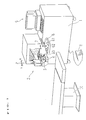
- Fig. 1 is an external view showing a schematic construction of an apparatus for a corneal surgery by using an excimer laser beam.
- Reference numeral 1 indicates a primary body of a surgery apparatus, and the excimer laser beam source and the like are contained in the primary body 1.
- the laser beam irradiated from the excimer laser beam source is reflected by mirrors and is guided to an arm part 2.
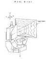
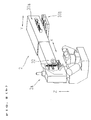
- the inside of the arm part 2 is provided with a light course for a laser beam, and the optical elements, such as mirror and the like, are disposed in it (see Fig. 2(a)).
- the arm part 2 contains a microscope 3, an illumination part 4, and undermentioned eyeball position detecting optical system and so on, and moves in X-direction (right and left direction against the ophthalmologist) by being controlled by the X-direction arm driving device 31a and in Y-direction (before and behind direction against the ophthalmologist) by being controlled by the Y-direction arm driving device 31b, and an arm tip 2a moves in Z-direction (direction of the laser beam irradiating optical axis) by being controlled by the Z-direction arm driving device 32.
- Respective arm driving devices include motors and sliding mechanism (see Fig. 2(b)).
- Reference numeral 6 indicates a controller including a joystick 7 for giving a signal to control the arm part 2 in XY-direction, and several kinds of operating switches.
- Reference numeral 8 indicates a foot switch for sending a laser output signal and reference numeral 9 indicates a computer for inputting some kinds of necessary data of operating condition, for calculating, displaying and storing the laser irradiating data, or the like.
- Reference numeral 10 is a bed for making the patient lie down thereon.
- Fig. 3 is a schematic view showing the optical system of the apparatus.
- Reference numeral 11 indicates a laser beam source for irradiating an excimer laser beam of 193 nm wave length.
- the laser beam irradiated from the laser beam source 11 is guided to an arm part 2 by mirrors 25 and 26 or the like.
- Reference numeral 12 indicates an aperture for limiting an irradiating region of the laser beam, and of which the aperture diameter is changed by an aperture driving device.
- Reference numeral 13 is a projection lens for projecting an aperture 12 on a cornea of a patient eye 15. Through projection lens 13, the aperture 12 is located on conjugate position with the cornea, and the region limited by the aperture 12 is projected on the cornea, and then the region of keratectomy is limited.
- the laser beam having rectangular cross section irradiated from a laser beam source 11 moves to the predetermined direction based on the parallel movement of the mirror 26, and covers whole region of the aperture 12.
- Reference numeral 14 indicates a dichroic mirror for reflecting an excimer laser beam and transmitting visible rays and infrared rays, and makes the optical axis of the laser beam irradiating optical system share the optical axis with the optical axis both of the observation system and the eyeball position detecting system, which will be undermentioned.
- Reference numeral 17 indicates an objective lens and reference numeral 18 indicates a dichroic mirror for transmitting visible rays and for reflecting infrared rays.
- the ophthalmologist observes the patient eye 15 by using the binocular microscope 3.
- the reticle plate which is not shown, is inserted into the observation system and the reticle plate can be the standard for the alignment in XY-direction of the patient eye.
- an object projecting system composed of two slits (referred to Japanese Publication (kokai) No.HEI6-47001(1994) (U.S. Patent application number 08/090,611)) is disposed in the observation optical system for alignment in Z-axis direction.
- Reference numeral 16 indicates a fixation lamp placed on the observation optical axis.
- Reference numeral 20 indicates an IR-rays illumination light source such as LED or the like, and 4 members of IR-rays illumination light sources 20 are disposed at intervals of 90° each other around the optical axis as the center.
- Reference numeral 21 is an image camera lens
- reference numeral 22 is a reflecting mirror
- reference numeral 23 is an IR-rays transmitting filter
- reference numeral 24 is a CCD camera.
- a flux of light beams of anterior portion image of the patient eye illuminated by the IR-rays illumination light source 20 is reflected by the dichroic mirror 18 through both the dichroic mirror 14 and objective lens 17.
- the image is formed on the photo-imaging plain of the CCD camera 24 by an image camera lens 21 through both the reflecting mirror 22 and the IR-rays transmitting filter 23.
- the IR-rays transmitting filter 23 cuts visible rays reflected slightly by the dichroic mirror 18.
- a CCD camera 24 detects the eyeball position as followings.
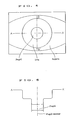
- Fig. 4 is a view of anterior portion image of the eye photographed by the CCD camera 24, and
- Fig. 5 is a view of distribution of light volume on line A-A' (Fig. 4) based on the image signal transmitted from the CCD camera 24.
- the respective light volumes are different by which the pupil, the iris and the sclera, therefore according to the information, the pupil edge coordinates in lateral direction can be detected, furthermore, in accordance with the detection of the pupil edge, the center position, so called, the pupil center coordinates in lateral direction is can be obtained.
- the pupil center coordinates in longitudinal direction can be obtained by using information of distribution of light volume on longitudinal line B-B'.
- the pupil position against the optical axis of the detecting optical system (so called the optical axis of the laser beam irradiating optical system), which is regulated so as to be the predetermined positional relation on the photo-imaging elements of the CCD camera 24 is obtained.
- the lateral and longitudinal detecting lines are desirable to be averaged in response to the information concerning distribution of light volume of plural lines which centers the middle of photo-imaging elements of the CCD camera 24.
- the center position of gravity is obtained based on the whole pupil region.
- the reflecting light of the cornea transmitted from the IR-rays illumination light source 20 is also transmitted to the CCD camera 24, but by placing the IR-rays illumination light source 20 so that the reflecting image of the cornea may not interrupt the detecting lines (lateral and longitudinal), the reflecting light of the cornea is prohibited from being noise light in the case that the positional coordinates is detected. Namely, it makes the line, which linked by two opposite light sources, slant to 45° against the detecting lines (lateral and longitudinal), and makes the image of light source to be seen around the cornea.
- the composition of such arrangement as described above is not indispensable, in a word, it is satisfied by that the pupil edge (or an iris) can be detected.
- the ophthalmic surgery apparatus is connected to a power source and is made the system run, the menu frame is displayed at the CRT monitor display of the computer 9.
- the ways of the cornea operation by using an excimer laser beam are PRK (photorefractive keratectomy) operating mode and PTK (phototherapeutic keratectomy) operating mode, in this case, the ophthalmologist selects the PRK operating mode from the menu frame.
- the ophthalmologist inputs several kinds of data such as the refractive power value of the patient eye 15 and operating conditions or the like, which are detected beforehand, by using the keyboard of the computer 9.
- the computer 9 calculates the resection volume of the cornea or the like based on the inputted data.
- the calculated operating data are transmitted to the control device 30 instructed by keyboard operation.
- the ophthalmologist makes the patient lie down on the bed 10 and the ophthalmologist places the arm part 2 provided a laser beam irradiating orifice above the patient eye 15.
- the ophthalmologist turns on each of the light sources, and fixes the fixation lamp 16 to the patient eye 15.
- the ophthalmologist observes anterior portion of the patient eye 15 illuminated by the illumination part 4 though the microscope 3, and he each aligns XY-direction by operating the joystick 7 and aligns Z-direction by operating the focus adjustment switch so as to be the predetermined relation between the reticle, which is not shown, and the pupil.
- the control device 30 makes the XY-direction arm driving devices 31a, 31b (and the Z-direction arm driving device 32) go into run, and moves the arm part 2 to XY-direction (and Z-direction).
- the automatic alignment changing switch 61 which is mounted on the controller 6, is turned on, the automatic alignment goes into run.
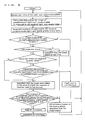
- the apparatus makes the X, Y-direction arm driving devices 31a, 31b go into run so that the optical axis of the laser irradiating optical system can be coincide with the pupil center, and then makes the arm part 2 move to XY-direction.
- the eyeball tracking mechanism goes into operation, which stores the predetermined position on the photo-imaging elements (the position of the optical axis of the laser beam irradiating optical system) of the CCD camera 24 as the standard position and moves the arm part 2 so that the pupil center can be coincide with the standard position.
- the pupil center position obtained by processing signals of the CCD camera 24 is compared with the standard position at any time, if the patient eye 15 moves in outside of the predetermined permissible region, the control device 30 moves the arm part 2 to the XY-direction by driving the X,Y-direction arm driving devices 31a, 31b on the bases of the comparative information, and makes the center position of the pupil be within the permissible region of the standard position. Moreover, in the case that the patient eye moves in outside of the XY-direction moving region, the apparatus makes the safety shutter device 35 goes into run, and cuts off the laser beam irradiation.
- the safety shutter 35 is released and the irradiation of the excimer laser beam is made ready. Then, after the ophthalmologist steps on the foot switch 8, the control device 30 emits the laser beam. The excimer laser beam is transmitted to the patient eye 15 through the laser beam irradiating optical system, and the cornea is ablated.
- the eyeball tracking is performed on the basis of the optical axis position of the laser beam irradiating optical system decided by the alignment operation by using the joystick, the optical axis of the laser beam irradiating optical system is placed on the target position by operating both the joystick 7 and the focus adjustment switch 60.
- the pupil center position of the patient eye 15 is stored as the standard position (the standard position of this moment is different from the optical axis of the laser beam irradiating optical system).
- the eyeball tracking mechanism which moves the arm part 2 so that the detected pupil position may coincide with the stored standard position, goes into run and the cornea is ablated the same as above mentioned.
- the eyeball position detection calculates the pupil edge based on the information of distribution of light volume of anterior portion of the eye, and thereby the pupil center is obtained on the basis of the pupil edge, but, among the reflecting light volume of the pupil, that of iris, that of sclera and that of cillosis, the reflecting light volume transmitted from the pupil is extremely little, so it can be also capable of detecting the pupil position (displacement direction from the optical axis) according to the light-and-shade degree of light volume distribution on the photo-imaging plane of the CCD camera 24. In followings, the alignment performed by this detection will be described.
- the image which centers the optical axis O is divided into 16 areas (S1 ⁇ S16) of 4 ⁇ 4 against the two-dimensional image transmitted from the CCD camera 24.
- the positions of the pixel are previously determined, against the pixel of respective areas (125 pixel ⁇ 125 pixel), so that the predetermined number of pixel (for example, 64 articles), which are detecting objects for light-and-shade, may equally distributed in the area (all the pixel are can be the detecting objects, but if the required number for detecting are taken as the objects, the processing speed can be faster).
- the image signals transmitted from the CCD camera 24 are transformed into digital data by the signal-process sensing circuit 34, and then, processed by predetermined process, and inputted into the control device 30. Based on the inputted signals, the control device 30 obtains the light-and-shade degree in response to the pixel which are previously determined every area. Since the light-and-shade degree every one pixel is transformed into digital data, therefore, for example, it can be obtained as the numerical value of light-and-shade degree of 256 grades from 0 to 255 (0 side is the darkest, 255 side is the brightest).
- the control device 30 obtains the value of the light-and-shade information of the image which is previously determined every area, and then, takes out the light-and-shade information of predetermined grades (for example, 20 grades) based on the lowest (the darkest) grade of the light-and-shade value as the standard among them, and counts the number of pixel within the predetermined range of light-and-shade value in respective areas. Then, it is judged that whether the number of pixel, which are counted in respective areas, satisfies the predetermined number (for example, 20 articles) or more, or not.
- predetermined grades for example, 20 grades
- the pupil part In the case that it satisfies the predetermined number, it is judged that the pupil part (or the iris part around the pupil) is in the area. In the case that the number of pixel is little, it is judged that the pupil part is not detected, since only a section of the pupil part is in the area, or the section, of which the light-and-shade value is low such as eyelashes, is overlapped on.
- the pupil part exists in the area of which the number of counted pixel are the largest, and after that, it is judged that whether the number of counted pixel of the 4 members of areas of S6, S7, S10, S11, which center the optical axis O, are equal (equal within the predetermined range) or not, if there are differences, according to the position of the area of which the pupil exists, X,Y-direction arm driving device 31a, 31b are driven and controlled toward the direction to which the differences are dissolved.
- the division of the area in response to the two-dimensional image transmitted from the CCD camera 24 it can also be capable of dividing into 4 areas which center the optical axis O, simply.
- the alignment in large range is performed according to the pupil part detection based on the light-and-shade information, and when the pupil edge detection is made possible, it is performed according to the pupil edge detection based on the pupil center position.
- the present invention may be embodied in other specific forms without departing from the spirit or essential characteristics thereof.
- this invention can be enforced without related to the construction of the optical system of the laser beam irradiating optical system such as refraction reform or the like, and in the case of the eyeball tracking which based on the optical axis position, decided by the ophthalmologist, of the laser beam irradiating optical system, the alignment operation is also easier by deciding the position in previous inspection and inputting the difference between the position and the pupil center.
Landscapes
- Health & Medical Sciences (AREA)
- Ophthalmology & Optometry (AREA)
- Heart & Thoracic Surgery (AREA)
- Vascular Medicine (AREA)
- Optics & Photonics (AREA)
- Surgery (AREA)
- Engineering & Computer Science (AREA)
- Biomedical Technology (AREA)
- Physics & Mathematics (AREA)
- Nuclear Medicine, Radiotherapy & Molecular Imaging (AREA)
- Life Sciences & Earth Sciences (AREA)
- Animal Behavior & Ethology (AREA)
- General Health & Medical Sciences (AREA)
- Public Health (AREA)
- Veterinary Medicine (AREA)
- Laser Surgery Devices (AREA)
- Eye Examination Apparatus (AREA)
Applications Claiming Priority (6)
| Application Number | Priority Date | Filing Date | Title |
|---|---|---|---|
| JP27632795 | 1995-09-29 | ||
| JP27632795 | 1995-09-29 | ||
| JP276327/95 | 1995-09-29 | ||
| JP22450996 | 1996-08-06 | ||
| JP22450996A JP3655022B2 (ja) | 1995-09-29 | 1996-08-06 | 眼科手術装置 |
| JP224509/96 | 1996-08-06 |
Publications (3)
| Publication Number | Publication Date |
|---|---|
| EP0765648A2 true EP0765648A2 (de) | 1997-04-02 |
| EP0765648A3 EP0765648A3 (de) | 1998-09-23 |
| EP0765648B1 EP0765648B1 (de) | 2004-01-14 |
Family
ID=26526102
Family Applications (1)
| Application Number | Title | Priority Date | Filing Date |
|---|---|---|---|
| EP19960306887 Expired - Lifetime EP0765648B1 (de) | 1995-09-29 | 1996-09-20 | Gerät für die Augenchirurgie |
Country Status (3)
| Country | Link |
|---|---|
| EP (1) | EP0765648B1 (de) |
| JP (1) | JP3655022B2 (de) |
| DE (1) | DE69631311T2 (de) |
Cited By (19)
| Publication number | Priority date | Publication date | Assignee | Title |
|---|---|---|---|---|
| WO1999023936A3 (en) * | 1997-11-11 | 1999-12-09 | Irvision Inc | Apparatus and method for tracking eye movements |
| WO1999062442A1 (de) * | 1998-05-29 | 1999-12-09 | Wavelight Laser Technologie Gmbh | Vorrichtung für eine medizinische behandlung mit einer lichtquelle |
| EP0983757A2 (de) | 1998-09-04 | 2000-03-08 | Nidek Co., Ltd. | Vorrichtung zur Chirurgie der Hornhaut |
| WO2000076435A1 (de) * | 1999-06-10 | 2000-12-21 | Wavelight Lasertechnologie Ag | Vorrichtung für eine medizinische behandlung des auges mit laserstrahlung |
| US6257722B1 (en) | 1999-05-31 | 2001-07-10 | Nidek Co., Ltd. | Ophthalmic apparatus |
| WO2001078632A1 (en) * | 2000-04-13 | 2001-10-25 | Nikon Corporation | Laser therapy apparatus |
| US6607527B1 (en) | 2000-10-17 | 2003-08-19 | Luis Antonio Ruiz | Method and apparatus for precision laser surgery |
| US7123751B1 (en) | 1999-06-03 | 2006-10-17 | Nidek Co., Ltd. | Ophthalmic apparatus, ophthalmic system and method for managing ophthalmic data |
| US7135016B1 (en) | 2000-05-08 | 2006-11-14 | Optotech Ltd. | Non-penetrating filtration surgery |
| WO2007016132A3 (en) * | 2005-07-29 | 2007-03-22 | Alcon Refractive Horizons Inc | Ophthalmic device lateral positioning system and associated methods |
| WO2008039695A1 (en) * | 2006-09-27 | 2008-04-03 | Bausch & Lomb Incorported | Apparatus and method for determining a position of an eye |
| WO2008055604A1 (en) | 2006-11-10 | 2008-05-15 | Carl Zeiss Meditec Ag | Ophthalmic apparatus and ophthalmic method for positioning an eye of a patient in a predetermined nominal position |
| US7431457B2 (en) | 2002-05-30 | 2008-10-07 | Amo Manufacturing Usa, Llc | Methods and systems for tracking a torsional orientation and position of an eye |
| US7458683B2 (en) | 2003-06-16 | 2008-12-02 | Amo Manufacturing Usa, Llc | Methods and devices for registering optical measurement datasets of an optical system |
| US7886747B2 (en) | 2000-05-08 | 2011-02-15 | I Optima Ltd. | Non-penetrating filtration surgery |
| US8556885B2 (en) | 1999-10-21 | 2013-10-15 | Bausch & Lomb Incorporated | Iris recognition and tracking for optical treatment |
| CN104287886A (zh) * | 2014-10-23 | 2015-01-21 | 上海交通大学医学院附属第九人民医院 | 用于光学导航系统的眼眶外科柔性工具尖端的定位装置 |
| WO2015171611A1 (en) | 2014-05-05 | 2015-11-12 | Health Research, Inc. | Clinical intravital microscope |
| US9629750B2 (en) | 2012-04-18 | 2017-04-25 | Technolas Perfect Vision Gmbh | Surgical laser unit with variable modes of operation |
Families Citing this family (11)
| Publication number | Priority date | Publication date | Assignee | Title |
|---|---|---|---|---|
| US6283954B1 (en) * | 1998-04-21 | 2001-09-04 | Visx, Incorporated | Linear array eye tracker |
| JP4609838B2 (ja) | 2004-08-10 | 2011-01-12 | 株式会社ニデック | 角膜手術装置 |
| JP4975305B2 (ja) * | 2004-12-01 | 2012-07-11 | 株式会社ニデック | 眼科装置 |
| US8221399B2 (en) | 2004-12-01 | 2012-07-17 | Nidek Co., Ltd. | Ophthalmic apparatus |
| AU2006275852B2 (en) * | 2005-07-29 | 2012-02-16 | Alcon Inc. | Ophthalmic device positioning system and associated methods |
| EP1757969A1 (de) * | 2005-08-24 | 2007-02-28 | Olympus Corporation | Mikroskopbewegungseinheit und Mikroskopgerät |
| JP5028073B2 (ja) | 2006-11-29 | 2012-09-19 | 株式会社ニデック | 角膜手術装置 |
| JP4933413B2 (ja) | 2007-12-11 | 2012-05-16 | 株式会社トーメーコーポレーション | 前眼部光干渉断層撮影装置及び前眼部光干渉断層撮影方法 |
| WO2009101696A1 (ja) * | 2008-02-14 | 2009-08-20 | Hidekazu Hirokawa | 眼球運動の視軸照射軸同軸化追尾装置の作動方法 |
| JP6880606B2 (ja) * | 2016-08-30 | 2021-06-02 | 株式会社ニデック | 眼科用手術顕微鏡 |
| JP7528933B2 (ja) * | 2019-05-31 | 2024-08-06 | 株式会社ニコン | 光干渉断層撮影装置及び光学モジュール |
Family Cites Families (6)
| Publication number | Priority date | Publication date | Assignee | Title |
|---|---|---|---|---|
| US4443075A (en) * | 1981-06-26 | 1984-04-17 | Sri International | Stabilized visual system |
| US4848340A (en) * | 1988-02-10 | 1989-07-18 | Intelligent Surgical Lasers | Eyetracker and method of use |
| US5098426A (en) * | 1989-02-06 | 1992-03-24 | Phoenix Laser Systems, Inc. | Method and apparatus for precision laser surgery |
| EP0630205A4 (de) * | 1992-02-27 | 1995-06-14 | Phoenix Laser Systems Inc | Automatisierte laser-einheit für hochgenaue chirurgische und industrielle eingriffe. |
| DE4232021C2 (de) * | 1992-09-24 | 1997-07-17 | Augon Ges Fuer Die Entwicklung | Vorrichtung zur Behandlung einer Augenhornhaut mittels eines Behandlungslaserstrahls |
| IL108672A (en) * | 1993-02-19 | 1997-07-13 | Phoenix Laser Systems | System for detecting, measuring and compensating for lateral movements of a target |
-
1996
- 1996-08-06 JP JP22450996A patent/JP3655022B2/ja not_active Expired - Fee Related
- 1996-09-20 EP EP19960306887 patent/EP0765648B1/de not_active Expired - Lifetime
- 1996-09-20 DE DE1996631311 patent/DE69631311T2/de not_active Expired - Lifetime
Cited By (30)
| Publication number | Priority date | Publication date | Assignee | Title |
|---|---|---|---|---|
| WO1999023936A3 (en) * | 1997-11-11 | 1999-12-09 | Irvision Inc | Apparatus and method for tracking eye movements |
| WO1999062442A1 (de) * | 1998-05-29 | 1999-12-09 | Wavelight Laser Technologie Gmbh | Vorrichtung für eine medizinische behandlung mit einer lichtquelle |
| EP0983757A2 (de) | 1998-09-04 | 2000-03-08 | Nidek Co., Ltd. | Vorrichtung zur Chirurgie der Hornhaut |
| EP0983757A3 (de) * | 1998-09-04 | 2001-09-19 | Nidek Co., Ltd. | Vorrichtung zur Chirurgie der Hornhaut |
| US6585723B1 (en) | 1998-09-04 | 2003-07-01 | Nidek Co., Ltd. | Corneal surgery apparatus |
| US7008414B2 (en) | 1998-11-30 | 2006-03-07 | Nikon Corporation | Laser treatment apparatus |
| US6257722B1 (en) | 1999-05-31 | 2001-07-10 | Nidek Co., Ltd. | Ophthalmic apparatus |
| US7123751B1 (en) | 1999-06-03 | 2006-10-17 | Nidek Co., Ltd. | Ophthalmic apparatus, ophthalmic system and method for managing ophthalmic data |
| US6755817B1 (en) | 1999-06-10 | 2004-06-29 | Wavelight Lasertechnologie Ag | Device for medical treatment of the eye using laser illumination |
| WO2000076435A1 (de) * | 1999-06-10 | 2000-12-21 | Wavelight Lasertechnologie Ag | Vorrichtung für eine medizinische behandlung des auges mit laserstrahlung |
| US8556885B2 (en) | 1999-10-21 | 2013-10-15 | Bausch & Lomb Incorporated | Iris recognition and tracking for optical treatment |
| WO2001078632A1 (en) * | 2000-04-13 | 2001-10-25 | Nikon Corporation | Laser therapy apparatus |
| US7135016B1 (en) | 2000-05-08 | 2006-11-14 | Optotech Ltd. | Non-penetrating filtration surgery |
| US7886747B2 (en) | 2000-05-08 | 2011-02-15 | I Optima Ltd. | Non-penetrating filtration surgery |
| WO2002032353A3 (en) * | 2000-10-17 | 2003-10-30 | Luis A Ruiz | Method and apparatus for precision laser surgery |
| US6607527B1 (en) | 2000-10-17 | 2003-08-19 | Luis Antonio Ruiz | Method and apparatus for precision laser surgery |
| US10251783B2 (en) | 2002-05-30 | 2019-04-09 | Amo Manufacturing Usa, Llc | Methods and systems for tracking a torsional orientation and position of an eye |
| US9596983B2 (en) | 2002-05-30 | 2017-03-21 | Amo Manufacturing Usa, Llc | Methods and systems for tracking a torsional orientation and position of an eye |
| US7431457B2 (en) | 2002-05-30 | 2008-10-07 | Amo Manufacturing Usa, Llc | Methods and systems for tracking a torsional orientation and position of an eye |
| US8740385B2 (en) | 2002-05-30 | 2014-06-03 | Amo Manufacturing Usa, Llc | Methods and systems for tracking a torsional orientation and position of an eye |
| US7458683B2 (en) | 2003-06-16 | 2008-12-02 | Amo Manufacturing Usa, Llc | Methods and devices for registering optical measurement datasets of an optical system |
| WO2007016132A3 (en) * | 2005-07-29 | 2007-03-22 | Alcon Refractive Horizons Inc | Ophthalmic device lateral positioning system and associated methods |
| US7478908B2 (en) | 2006-09-27 | 2009-01-20 | Bausch & Lomb Incorporated | Apparatus and method for determining a position of an eye |
| WO2008039695A1 (en) * | 2006-09-27 | 2008-04-03 | Bausch & Lomb Incorported | Apparatus and method for determining a position of an eye |
| US8292432B2 (en) | 2006-11-10 | 2012-10-23 | Carl Zeiss Meditec Ag | Ophthalmic apparatus and ophthalmic method for positioning an eye of a patient in a predetermined nominal position |
| WO2008055604A1 (en) | 2006-11-10 | 2008-05-15 | Carl Zeiss Meditec Ag | Ophthalmic apparatus and ophthalmic method for positioning an eye of a patient in a predetermined nominal position |
| US9629750B2 (en) | 2012-04-18 | 2017-04-25 | Technolas Perfect Vision Gmbh | Surgical laser unit with variable modes of operation |
| WO2015171611A1 (en) | 2014-05-05 | 2015-11-12 | Health Research, Inc. | Clinical intravital microscope |
| EP3140691A4 (de) * | 2014-05-05 | 2018-01-03 | Health Research, Inc. | Klinisches intravitalmikroskop |
| CN104287886A (zh) * | 2014-10-23 | 2015-01-21 | 上海交通大学医学院附属第九人民医院 | 用于光学导航系统的眼眶外科柔性工具尖端的定位装置 |
Also Published As
| Publication number | Publication date |
|---|---|
| JPH09149914A (ja) | 1997-06-10 |
| EP0765648A3 (de) | 1998-09-23 |
| DE69631311D1 (de) | 2004-02-19 |
| DE69631311T2 (de) | 2004-10-21 |
| EP0765648B1 (de) | 2004-01-14 |
| JP3655022B2 (ja) | 2005-06-02 |
Similar Documents
| Publication | Publication Date | Title |
|---|---|---|
| EP0765648A2 (de) | Gerät für die Augenchirurgie | |
| US6159202A (en) | Corneal surgery apparatus | |
| EP0850614B1 (de) | Anordnung zur Durchführung von Augenoperationen | |
| US6257722B1 (en) | Ophthalmic apparatus | |
| EP0947158B1 (de) | Ophthalmologisches Gerät | |
| JP3978024B2 (ja) | 眼科装置及び角膜手術装置 | |
| JP4021136B2 (ja) | 角膜手術装置 | |
| EP1486160B1 (de) | Augenbeobachtungsgerät | |
| EP1138290B1 (de) | Gerät zur Augenchirurgie | |
| EP1369078B1 (de) | Augenheikundegerät | |
| US7275829B2 (en) | Ophthalmic laser irradiation apparatus | |
| EP1123689B1 (de) | Ophthalmische Einrichtung | |
| JP2001029316A (ja) | 眼屈折力測定装置 | |
| JP3338717B2 (ja) | 眼科装置 | |
| US20030073984A1 (en) | Corneal-ablation-data determining apparatus and a corneal surgery apparatus | |
| JP3675852B2 (ja) | 眼科手術装置 | |
| JPH10192333A (ja) | 眼科手術装置 | |
| JP3264990B2 (ja) | 角膜内皮細胞撮影装置 | |
| JP2007054423A (ja) | 角膜手術装置 | |
| JP3872228B2 (ja) | レーザ手術装置 | |
| JP3656770B2 (ja) | 眼科装置 |
Legal Events
| Date | Code | Title | Description |
|---|---|---|---|
| PUAI | Public reference made under article 153(3) epc to a published international application that has entered the european phase |
Free format text: ORIGINAL CODE: 0009012 |
|
| AK | Designated contracting states |
Kind code of ref document: A2 Designated state(s): BE DE FR GB IT LU NL |
|
| PUAL | Search report despatched |
Free format text: ORIGINAL CODE: 0009013 |
|
| AK | Designated contracting states |
Kind code of ref document: A3 Designated state(s): BE DE FR GB IT LU NL |
|
| 17P | Request for examination filed |
Effective date: 19990305 |
|
| 17Q | First examination report despatched |
Effective date: 20021106 |
|
| GRAP | Despatch of communication of intention to grant a patent |
Free format text: ORIGINAL CODE: EPIDOSNIGR1 |
|
| GRAS | Grant fee paid |
Free format text: ORIGINAL CODE: EPIDOSNIGR3 |
|
| GRAA | (expected) grant |
Free format text: ORIGINAL CODE: 0009210 |
|
| RIN1 | Information on inventor provided before grant (corrected) |
Inventor name: ARASHIMA, MIKIO Inventor name: KANDA, HIDENORI Inventor name: SUMIYA, TOSHIHUMI |
|
| RAP1 | Party data changed (applicant data changed or rights of an application transferred) |
Owner name: NIDEK CO., LTD |
|
| AK | Designated contracting states |
Kind code of ref document: B1 Designated state(s): BE DE FR GB IT LU NL |
|
| PG25 | Lapsed in a contracting state [announced via postgrant information from national office to epo] |
Ref country code: NL Free format text: LAPSE BECAUSE OF FAILURE TO SUBMIT A TRANSLATION OF THE DESCRIPTION OR TO PAY THE FEE WITHIN THE PRESCRIBED TIME-LIMIT Effective date: 20040114 Ref country code: BE Free format text: LAPSE BECAUSE OF FAILURE TO SUBMIT A TRANSLATION OF THE DESCRIPTION OR TO PAY THE FEE WITHIN THE PRESCRIBED TIME-LIMIT Effective date: 20040114 |
|
| REG | Reference to a national code |
Ref country code: GB Ref legal event code: FG4D |
|
| RIN2 | Information on inventor provided after grant (corrected) |
Inventor name: ARASHIMA, MIKIO Inventor name: KANDA, HIDENORI Inventor name: SUMIYA, TOSHIHUMI |
|
| REF | Corresponds to: |
Ref document number: 69631311 Country of ref document: DE Date of ref document: 20040219 Kind code of ref document: P |
|
| NLV1 | Nl: lapsed or annulled due to failure to fulfill the requirements of art. 29p and 29m of the patents act | ||
| ET | Fr: translation filed | ||
| PG25 | Lapsed in a contracting state [announced via postgrant information from national office to epo] |
Ref country code: LU Free format text: LAPSE BECAUSE OF NON-PAYMENT OF DUE FEES Effective date: 20040920 |
|
| PLBE | No opposition filed within time limit |
Free format text: ORIGINAL CODE: 0009261 |
|
| STAA | Information on the status of an ep patent application or granted ep patent |
Free format text: STATUS: NO OPPOSITION FILED WITHIN TIME LIMIT |
|
| 26N | No opposition filed |
Effective date: 20041015 |
|
| PGFP | Annual fee paid to national office [announced via postgrant information from national office to epo] |
Ref country code: IT Payment date: 20100921 Year of fee payment: 15 Ref country code: FR Payment date: 20100921 Year of fee payment: 15 |
|
| PGFP | Annual fee paid to national office [announced via postgrant information from national office to epo] |
Ref country code: GB Payment date: 20100916 Year of fee payment: 15 |
|
| PGFP | Annual fee paid to national office [announced via postgrant information from national office to epo] |
Ref country code: DE Payment date: 20100915 Year of fee payment: 15 |
|
| GBPC | Gb: european patent ceased through non-payment of renewal fee |
Effective date: 20110920 |
|
| PG25 | Lapsed in a contracting state [announced via postgrant information from national office to epo] |
Ref country code: IT Free format text: LAPSE BECAUSE OF NON-PAYMENT OF DUE FEES Effective date: 20110920 |
|
| REG | Reference to a national code |
Ref country code: FR Ref legal event code: ST Effective date: 20120531 |
|
| REG | Reference to a national code |
Ref country code: DE Ref legal event code: R119 Ref document number: 69631311 Country of ref document: DE Effective date: 20120403 |
|
| PG25 | Lapsed in a contracting state [announced via postgrant information from national office to epo] |
Ref country code: DE Free format text: LAPSE BECAUSE OF NON-PAYMENT OF DUE FEES Effective date: 20120403 |
|
| PG25 | Lapsed in a contracting state [announced via postgrant information from national office to epo] |
Ref country code: FR Free format text: LAPSE BECAUSE OF NON-PAYMENT OF DUE FEES Effective date: 20110930 Ref country code: GB Free format text: LAPSE BECAUSE OF NON-PAYMENT OF DUE FEES Effective date: 20110920 |